

SG Rotarybolt Z03 Installation Instructions Manual

Rotarybolt™ Z03 Electronic Safe Lock
Installation Instructions
Mounting Considerations:
• Sargent & Greenleaf Rotarybolt Z03 electronic safe locks are designed to use the same mounting screw
locations as common S&G mechanical and electronic safe locks. In many instances it can easily be
mounted in place of these locks.
• The Rotarybolt Z
03
lock is available in left-hand and right-hand models. The illustrations on page 2 will
help you determine which one you need for your particular application.
•
The keypad diameter is approximately 3 ¾ inches (95.2 mm), which
allows mounting in applications where limited space is a consideration.
• The lock can be used with either a one-battery or two-battery style
keypad. To meet VdS requirements, the one-battery keypad must
be installed using the included one-way security screw. If the twobattery style of keypad is used, it must be the tamper resistant model
(61KP-201) to meed VdS requirements. Standard installations do
not require the security screw for one-battery keypads, or they can be
accomplished using the non-tamper two-battery keypad (61KP-101 or
61KP-105).
• A fresh Duracell
®
alkaline battery should be installed in the keypad, and
the keypad should be connected to the lock to check for proper operation
prior to installation. Follow the procedures outlined in the operating
instruction booklet.
• Modifications to the lock are not recommended and will void the manufacturer’s warranty.
• A minimum distance of .150 inch (3,8 mm) is recommended between the end of the lock case
containing the bolt and the safe’s blocking bar or cam plate (which is normally blocked by the extended
lock bolt). Maintaining this clearance will allow the lock to achieve optimum performance.
•
Personal data that can be directly related to a code holder, such as a birth date, street number, or phone
number, should not be used in creating a lock code. Avoid codes that can be easily guessed.
Note: This lock has been Listed by Underwriters Laboratories for use with the following S&G keypad(s):
6120-0XX, 6120-2XX, 6160-2XX (IP Series), 61KP-1XX, 61KP-2XX, 6130-4XX, 6130-5XX
Sargent & Greenleaf, Inc.
A Wholly Owned Subsidiary of Stanley Security Solutions, Inc.
PO Box 930, Nicholasville, Kentucky 40340-0930 USA
Phone (859) 885-9411
Phone (800) 826-7652
FAX (859) 887-2057
FAX (800) 634-4843
Copyright© 2006, Sargent & Greenleaf
page 1
Sargent & Greenleaf S.A.
9, chemin du Croset
1024 Ecublens, Switzerland
Phone +41-21 694 34 00
FAX +41-21 694 34 09
Document 630-689ENG
Revised 1/2/2007
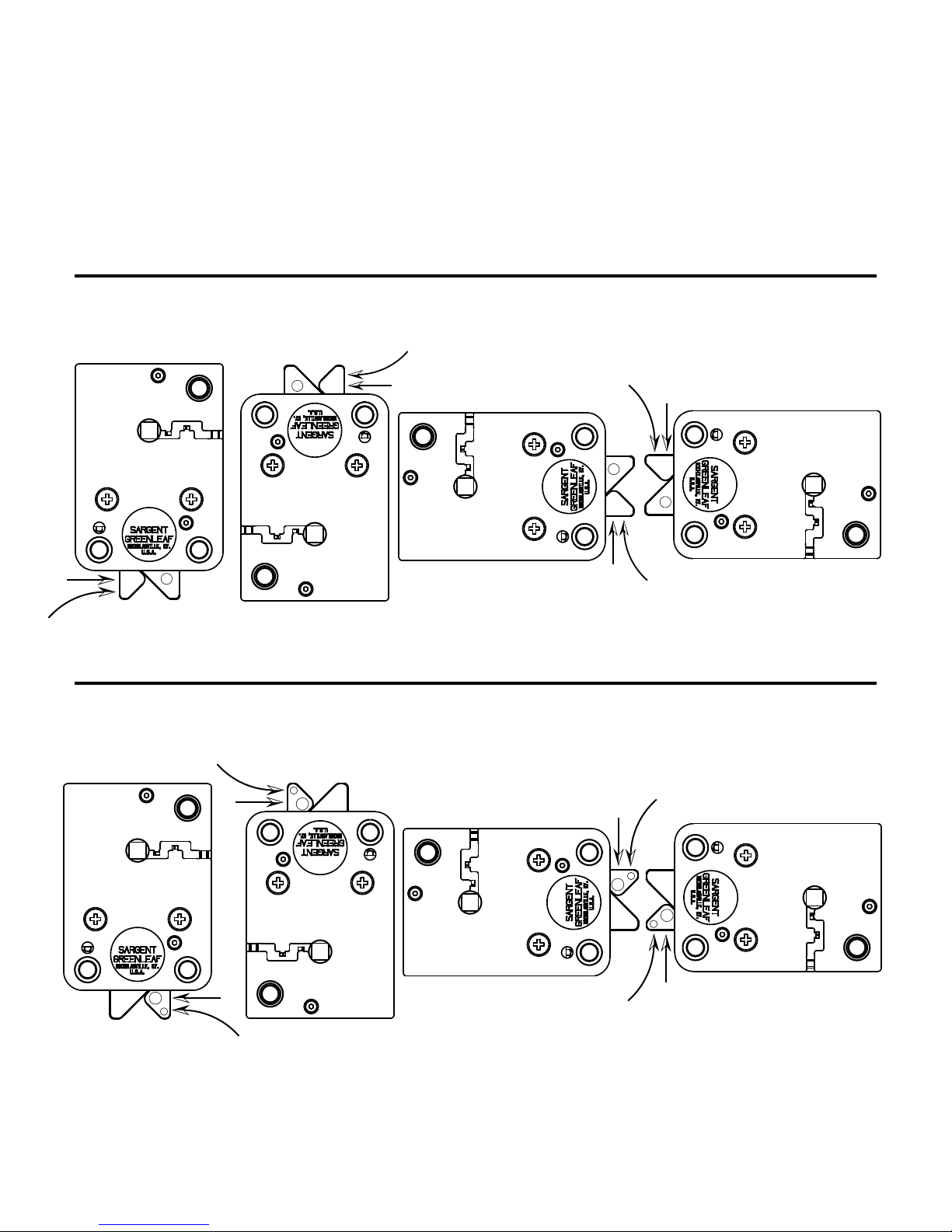
Left-hand or Right-hand?
The Rotarybolt Z03 lock uses a very efficient bolt design that allows it to “fold” into the lock case when the
correct code is entered and the safe’s boltwork presses against the side of the lock bolt. This provides for
smooth operation and long life. It also requires the lock to be handed, which means the direction from
which the safe’s boltwork presses against the Rotarybolt bolt determines which model must be used.
The illustrations below should make it easy for you to select the correct model for your safe. The arrows
represent the direction in which the safe’s blocking bar (straight arrow) or cam plate (curved arrow) moves
when the door’s handle is being turned to unlock the safe.
The four locks immediately below are all the same left-hand model (Model 2003-300 Rotarybolt Z03). Each is shown in one of the
four standard mounting positions. Each is depicted as it would be seen by looking at the back (inside) of the safe door.
LEFT-HAND MODEL 2003-300
MOUNTED VERTICAL-DOWN
LEFT-HAND MODEL 2003-300
MOUNTED RIGHT-HAND
LEFT-HAND MODEL 2003-300
MOUNTED VERTICAL-UP
LEFT-HAND MODEL 2003-300
MOUNTED LEFT-HAND
The four locks immediately below are all the same right-hand model (Model 2003-200 Rotarybolt Z03). Each is shown in one of the
four standard mounting positions. Each is depicted as it would be seen by looking at the back (inside) of the safe door.
RIGHT-HAND MODEL 2003-200
MOUNTED RIGHT-HAND
RIGHT-HAND MODEL 2003-200
MOUNTED LEFT-HAND
RIGHT-HAND MODEL 2003-200
MOUNTED VERTICAL-DOWN
RIGHT-HAND MODEL 2003-200
MOUNTED VERTICAL-UP
page 2

Installation Notes
Although the Rotarybolt Z03 lock is easy to install, we recommend the following procedures be performed
only by an experienced locksmith or safe technician. Your safe may incorporate relocking devices that are
attached to the lock body. Misalignment or detachment of these devices can result in a lockout; a condition
where the safe probably cannot be opened without damage.
The Rotarybolt Z03 lock requires a 9-volt alkaline battery. We recommend fresh Duracell® batteries. Do not
use an old or partially drained battery in your lock. A new battery will power your lock for approximately
8,000 openings when used without the time delay feature.
Installation . . .
Step 1
Remove the existing lock (if one is present). The
mounting plate should be smooth and flat, with
either 1/4 – 20 or M6 mounting screw holes. The
wire channel (spindle hole) must have a minimum
diameter of 5/16 inch.
Step 2
Use a reamer or file to remove any sharp edges
from the wire channel (spindle hole) that could
damage the wire cable.
Run the connector through the wire channel.
Gently pull the connector and all excess cable to
the outside of the safe. Make sure the cable is not
crimped or stressed at any point. It is also very
important make sure the cable is not crimped or
folded against itself under the lock body as you
prepare to fasten the lock to the mounting plate.
page 3

Step 3
Once you’ve double-checked to make sure the
wire cable is not crimped or in contact with
any sharp surface, attach the lock to the safe’s
mounting plate. Use the three 1/4 – 20 or M6
(metric) mounting screws provided. They should
be tightened to 30 - 40 inch-pounds (33.9 -
45.2. dNm)
The lock incorporates a bolt-though cover that
allows the mounting with the cover in place.
Removing the cover voids the product warranty.
Step 4
Once the lock is fastened into place, check
to make sure all three mounting screws are
tight. Avoid bottoming a screw in a mounting
plate hole. Although the screw will feel tight,
it will not be holding the lock firmly against
the plate.
Ensure a gap of at least .150 inch (3.8 mm)
between the end of the lock case and the
blocking bar of the safe’s boltwork. The gap
to be measured is indicated by the space
between the arrows.
Step 5
Pictured is an installation that requires attachment
of the safe manufacturer’s relock device plate to
the lock cover using the cover screws or a suitable
substitute. If your situation is similar, be sure the
thickness of the relock device plate is not great
enough to prevent the screws from engaging the
lock case by at least four threads. If necessary,
use longer 8-32 machine screws to insure proper
fit. The cover screw holes are only tapped as deep
as the original screws, so using other screws may
require tapping the screw holes slightly deeper into
the lock case. Cover screws must engage the lock
case by at least four threads.
If the relock device plate is not properly attached,
it may come loose. The safe will then have to be
forcibly opened.
page 4
 Loading...