

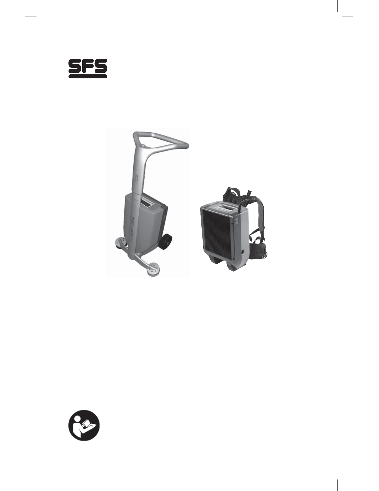
isoweld
®
3000 &
isoweld
®
Backpack
Operating Instructions
Installation Instructions
Version 2.0
North America - English

2
Table of contents
Operating Instructions
isoweld® induction welding tool 3
Symbols used 4
Rating plate 5
Safety instructions 5
Special safety instructions 8
Danger areas 10
System components isoweld®3000, isoweld®3000 Backpack 11
Overview isoweld®3000, isoweld® Backpack, Standard items supplied 13
Description of function 15
Transport 15
Power requirements 16
Start-up isoweld
®
3000, isoweld® Backpack 17
Calibration 21
Additional setting options 22
Test welding 22
Operation: welding 23
Checking the welding 25
Optional operation isoweld
®
3000, isoweld® Backpack:
working with the hand inductor 25
Technical data 26
Error messages 27
Disposal 28
Maintenance, service and warranty 28
Declaration of conformity 32
System components 35
Deciding on installation strategy 36
Preparing the roof for fastening 36
Measuring and marking fastening points 36
Fixing the stress plates 37
Rolling out the waterproof membrane 38
Marking the fastening points 38
Preparing the induction tool 39
Welding the membrane at the fastening points 40
Installation Instructions

3
Identification
Type: isoweld
®
3000, isoweld ® Backpack
Manufacturer: SFS
Division Construction
Rosenbergsaustrasse 10
CH-9435 Heerbrugg
Switzerland
www.sfsintec.biz
Rating: see type plate
The induction welding tool of the isoweld ® series has been designed in
Switzerland. The isoweld
®
3000 is assembled in Switzerland and the isoweld ®
Backpack is assembled in the US.
Responsible for documentation:
Daniel Gasser,
Reserach and Technology
Preface
Purpose of the document
This document is written for skilled building operatives working in the field of
flat roofs. It is intended to instruct skilled operatives in how to work safely and
efficiently with the units (see the section on "Safety instructions").
Structure of the documentation
The documentation describes all the phases in the life of the tool from transport,
installation, operation, maintenance and servicing up to disposal.
This manual was drawn up taking into account the provisions of the EU
Machinery Directive 2006/42/EC, Annex I, Clause 1.7.4 "Instructions".
The original operating instructions were prepared in German and modified in
English.
Keep this document safe
These operating instructions are part of the product and must be kept with the
unit at all times. They must be available to the operator at all times.
isoweld ® induction welding tool
4
Indicates a hazardous situation. Death or severe permanent injury could result if
the situation is not avoided.
Indicates a potentially hazardous situation. Death or severe permanent injury
could result if the situation is not avoided.
Indicates a potentially hazardous situation. Slight or minor permanent injury could
result if the situation is not avoided.
DANGER!
WARNING!
CAUTION!
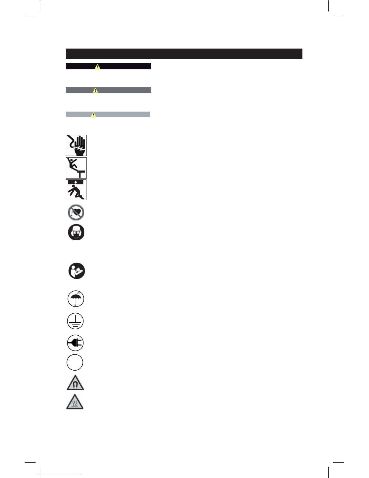
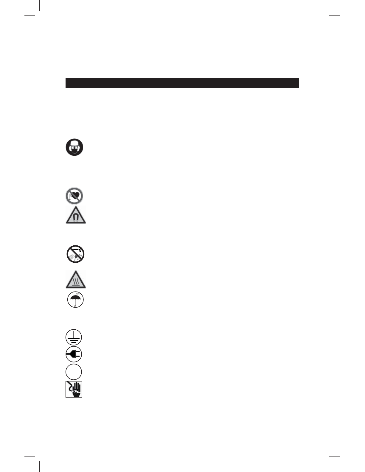
Symbols used
This symbol highlights hazard instructions that must be observed when
dealing with electrical equipment.
This symbol signals hazards that must be taken account of when
working on roofs.
This symbol signals hazards associated with crane transport.
This symbol signals risks for people who have a cardiac pacemaker.
This symbol makes clear the requirement to wear personal protective
equipment. Personal protective equipment always includes: safety
glasses, safety gloves, safety shoes, closely fitting working clothes
as well as a belt and safety rope. In every case the internal accident
prevention requirements must be observed.
The operating instructions must be read and understood before setting
up or using the tool. The instructions must be observed. Ask the
responsible department if the operating instructions are missing or if you
do not understand sections of the operating instructions.
This symbol signals hazards associated with magnetic fields.
FI
This symbol alerts operators to use the mandatory protective ground
conductor.
This symbol alerts operators to use the mandatory RCD switch.
This symbol alerts operators to use the mandatory protection against
moisture.
This symbol alerts operators to use the required network voltage.
This symbol highlights instructions that point out a fire hazard.
Instructions regarding additional important information.
5
Safety instructions
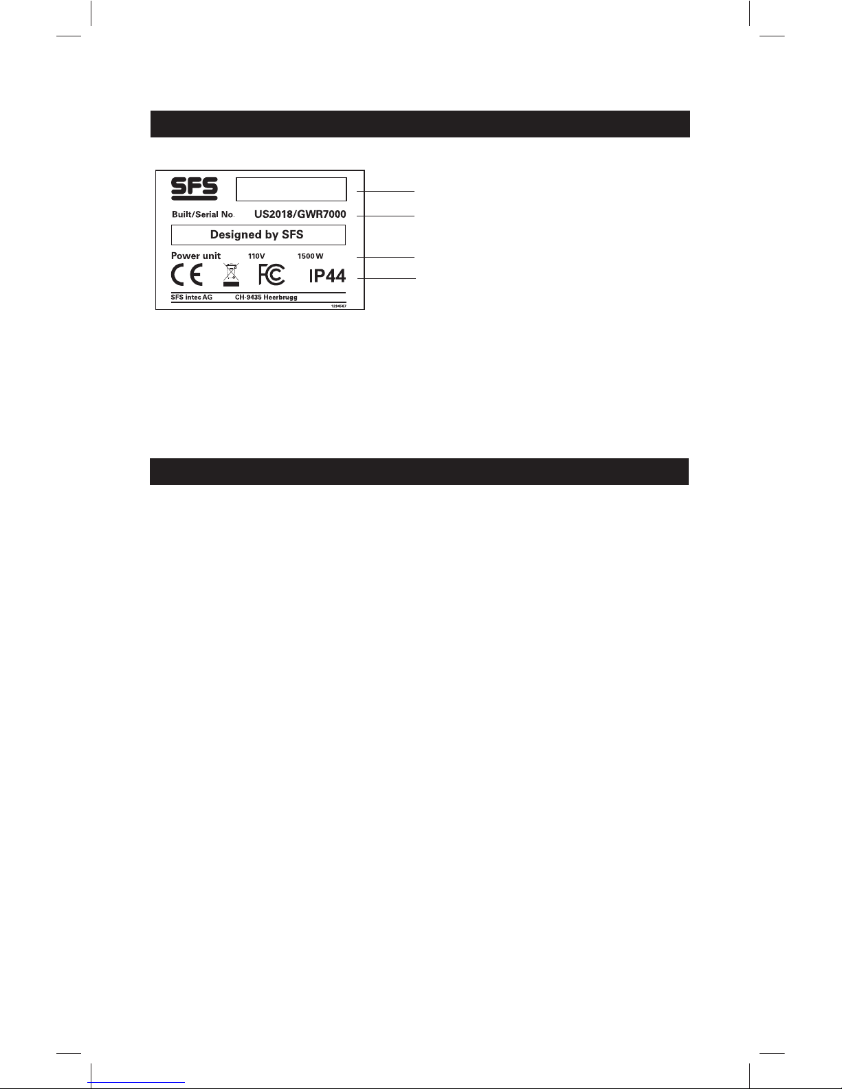
Rating plate
1 Machine type
2 Year of manufacture, serial number
3 Technical data
4 CE, FCC marking,Protection rating
Meaning of general safety instructions
The general safety instructions in this section provide information on possible
residual hazards that are always present or that could occur unexpectedly,
despite the correct usage of the unit.
The safety instructions must be observed by all persons who work on or with
the tool to prevent physical injury, damage or harm to the environment. These
persons are therefore obliged to read, understand and observe the provisions of
this section.
1
2
3
4
isoweld
®

6
Safety instructions
Meaning of specific safety instructions
For certain situations the applicable safety instructions are given at the relevant
place in the operating instructions. These instructions must be observed in order
to prevent physical injury, damage or harm to the environment.
Statutory requirements
In addition to the safety instructions in this operating manual, the statutory
accident prevention and environmental protection regulations applicable in the
country of use must be observed. Likewise the generally accepted rules for
safety and working in a technically correct manner must be observed.
Consequences of failure to observe the safety instructions
Failure to observe the safety instructions can lead to accidents with resultant
physical injury, damage or harm to the environment.
The manufacturer accepts no liability for injury or damage resulting from failure
to observe the safety instructions.
Intended use
The induction welding tool has been designed exclusively for the installation of
roofing membranes recommended by SFS on roofs.
Only fasteners, stress plates and sleeves approved for the tool and provided by
SFS may be used. The tool must be used within the limits defined in the
"Technical data" section.
Foreseeable misuse
• Starting to use the tool without instruction.
• Rendering the safety features inoperative and removing the warning labels.
• Working on roofs with a slope of more than 10°.
• Working backwards on roofs.
• Unsafeguarded or reckless working on roofs.
• Modifying the tool without the permission of the manufacturer.
• Using accessories or spare parts from another manufacturer without the
permission of SFS.
• Using or wearing isoweld
®
Backpack on an unstable support, steep incline or
ladder.
• In the case of misuse there is a risk of death or injury, damage to the tool
and damage to the material processed.
• It is not permitted to open the isoweld
®
induction generator under any
circumstances. Non-observance involves the risk of death or injury,
damage to the tool and damage to the processed material.
DANGER!
NOTICE
Welding with plates without an SFS
stamp may result in roof assembly failure.
USE ONLY SFS MARKED PLATES
7
• It is not permitted to use the isoweld
®
Backpack as a safety harness or wear
the isoweld® Backpack over a safety harness, under any circumstances.
Non-observance involves the risk of dealth or injury, damage to the tool and
damage to the processed material.
Safety instructions
• Keep your workplace tidy. An untidy workplace increases the risk
of accident.
• Keep children at a safe distance. Do not allow third parties to touch
the machine or the cable.
• It is imperative to comply with the safety regulations in the
respective country.
• Always wear the correct personal protective equipment when
working. Personal protective equipment includes: safety goggles,
safety gloves, safety shoes, closely fitting working clothes.
• When working on a roof it is possible for the tool or the operator to
accumulate a static charge. For this reason, we recommend that
anti-static clothing and anti-static shoes be worn and/or the use of
anti-static sprays.
• The induction welding tool and the magnets may have an effect on
the function of cardiac pacemakers and implanted defibrillators. It
is possible that cardiac pacemakers switch to test mode and cause
discomfort. It is possible that defibrillators cease to function. If you
are fitted with any such instruments, you must keep a minimum
distance of 20 inches (50 cm) from the inductor (also hand
inductor) and the magnets. You must warn persons fitted with such
instruments against coming too close to the magnets and inductors.
• Do not hold any objects containing metal in the direct proximity of
the inductor (e.g. watches, jewelry, keys, mobile phones, hearing
equipment, implants etc.).
• The
isoweld® stress plates become very hot due to the induction
process. There is a risk of burns when touching the stress plates
immediately following the welding process.
• Take account of environmental influences. Do not expose the
induction welding tool to rain. Do not use the induction welding
tool in damp or wet conditions. Ensure that you have good lighting.
Do not use the induction welding tool in the proximity of flammable
liquids or gases.
• Connect the tool to a socket with protective ground conductor. Any
breakage/disconnection of the protective conductor inside or
outside of the tool is potentially dangerous! Only use extension
cables with an earth conductor!
• The mains voltage must be as stated on the generator type plate.
• When the tool is used on building sites, the RCD switch is a
mandatory requirement for personal protection.
• Place the electric cable (supply cable) in a suitable location. Ensure
that it does not constitute a trip hazard and does not wear through.
Regularly check the electric cable, inductor cable and temperature
cable for damage.
• In the open, only use extension cables approved and marked for
this purpose.
General safety instructions – Part 1
FI
8
• Always switch the tool off and remove the mains connector during breaks or
maintenance work. Do not leave the tool unattended.
• When carrying out maintenance and service work, the power connection to
the tool must be disconnected.
• Regularly check the tool for damage, and that it is functioning properly. Use
the tool only if it is functioning properly.
• Repairs may only be carried out by a specialist.
• Only use system components from SFS or approved by SFS. Do not use any
accessories or spare parts from other manufacturers without approval by SFS.
•
The functionality of this system is guaranteed when original fastener, stress
plate, spare parts from SFS are used, and the unit is operated in accordance
with the operating instructions.
• Do not use or wear isoweld
®
Backpack on an unstable support, steep incline
or ladder.
• Always inspect isoweld
®
Backpack straps and connection points before use.
• Using an isoweld
®
Backpack tool with damaged straps or connection points
may result in a strap or connection breaking while in use and the machine
may fall causing personal injury.
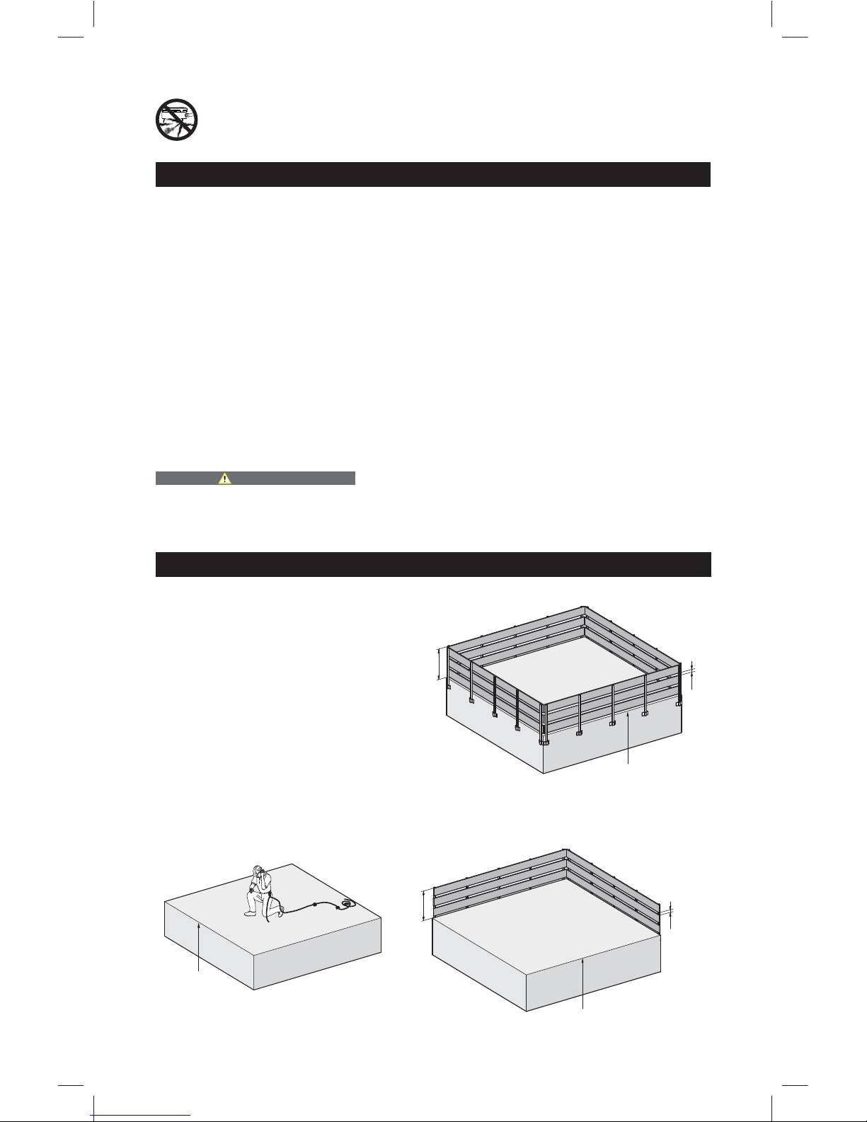
Special safety instructions
• When working on roofs with a
slope of between 0 and 10° a
guard rail must be fixed at the
edge of the roof.
• When the roof slope is more than
10° special safety devices must be
employed.
• When the working height is more
than 10 ft. (3 m) above ground,
appropriate fall prevention
measures must be employed
(see below).
• Fall prevention measures for work lasting less than 2 working days. In the case
of work that takes longer, proceed as described above (see below).
>5 m
>3 m
max. 47 cm
100 cm
max. 47 cm
100 cm
>5 m
Safety instructions
General safety instructions – Part 2
• Never start the welding process while the supply cable is under
the tool. Ensure that the cable is far enough away from the
inductor during the work process.
WARNING!

9
• Risk of falling through: beware of areas
in the roof that are not structurally safe,
e.g. rooflights, tarpaulins etc. These
areas must be appropriately marked and/
or secured with gangways.
• When working on roofs the entire risk
area on the ground must be cordoned
off and signed. It is important to ensure
that third parties are not endangered by
falling objects.
• Do not use or wear isoweld® Backpack on an unstable support, steep incline
or ladder.
• It is not permitted to use the isoweld
®
Backpack as a safety harness or wear
the isoweld
®
Backpack over a safety harness, under any circumstances.
Non-observance involves the risk of dealth or injury, damage to the tool and
damage to the processed material.
Special safety instructions
WARNING!
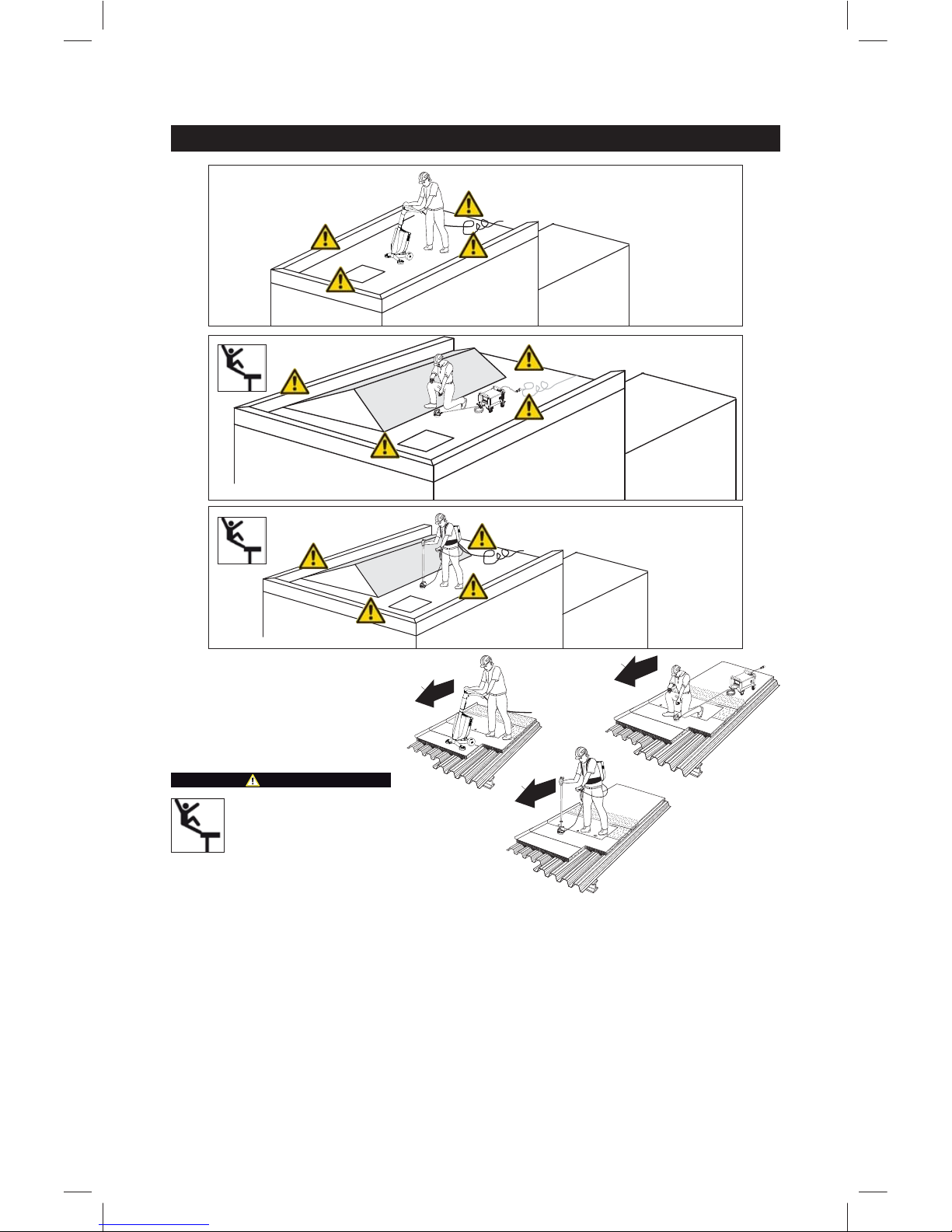
10
1 Fall hazard at roof edge
2 Fall hazard at step in roof
3 Break-through hazard, e.g.
glass windows
4 Trip hazard from cable
Always work in a forward
direction, never backwards.
Danger areas
1
DANGER!
3
4
1
1
2
3
3
4
4
1
1
1
2
2
11
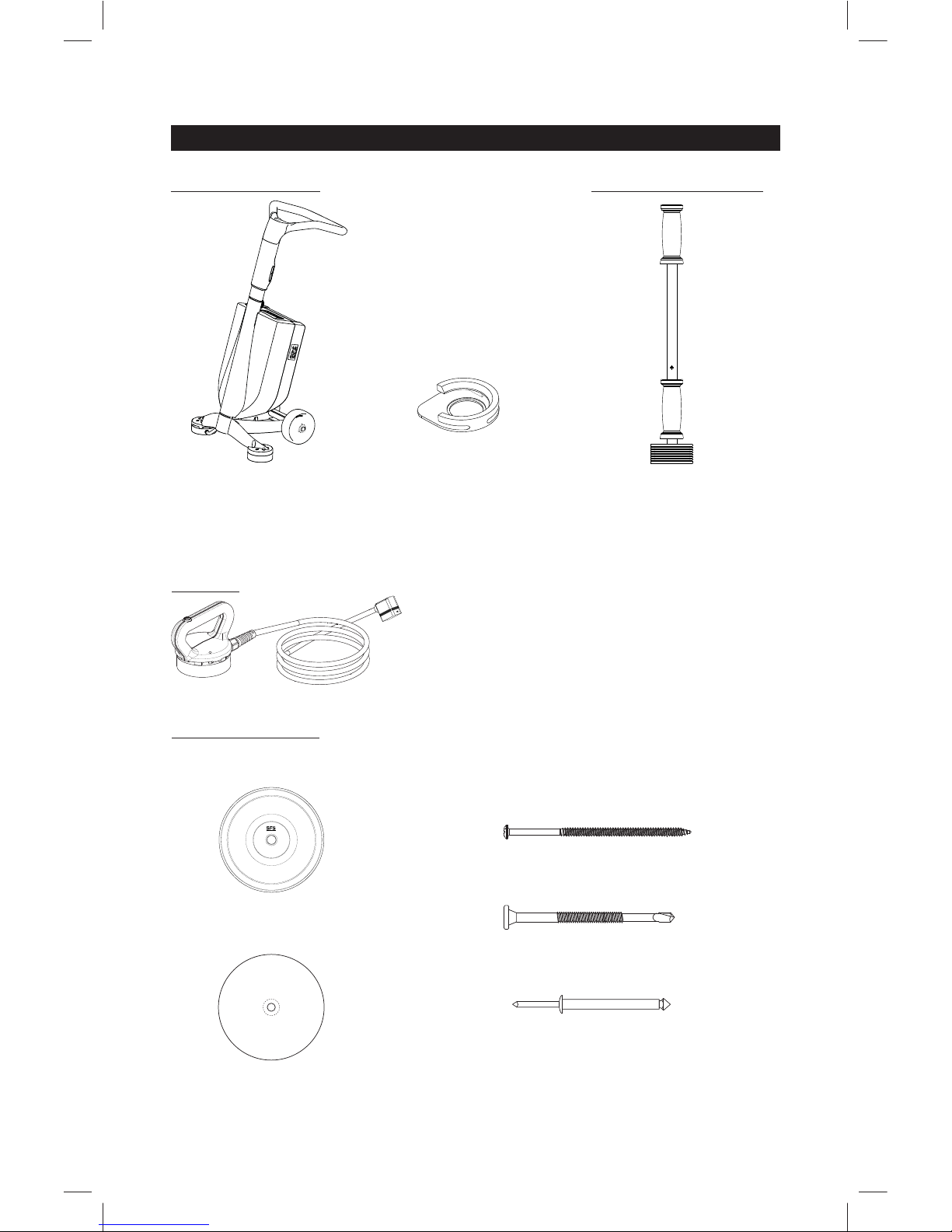
System components isoweld® 3000
Induction welding tool
isoweld® 3000
Magnet
FI Magnet
Calibration template
isoweld
®
Included in delivery:
Fixing components:
Additional accessories:
Hand inductor
FI-H
Optional:
Fastener:
DF-#15xL"
PUR-#12xL"
FI-P-6.8 isoweld
®
plate
for metallic systems
Stress plate:
TPR-L-6,3xL(mm)
FI-Pad

12
System components isoweld® Backpack
Magnet
FI Magnet
Fixing components:
Additional accessories:
Fastener:
DF-#15xL"
PUR-#12xL"
FI-P-6.8 isoweld® plate
for metallic systems
FI-Pad
Stress plate:
Calibration template
isoweld
®
Induction welding tool
isoweld® Backpack
Included in delivery:
TPR-L-6,3xL(mm)
13
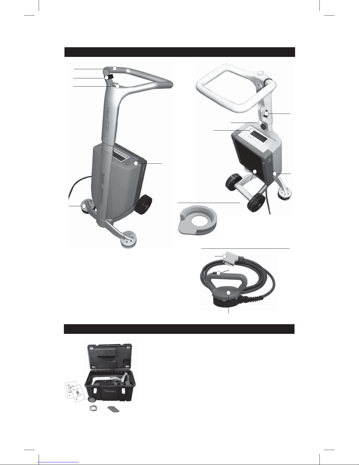
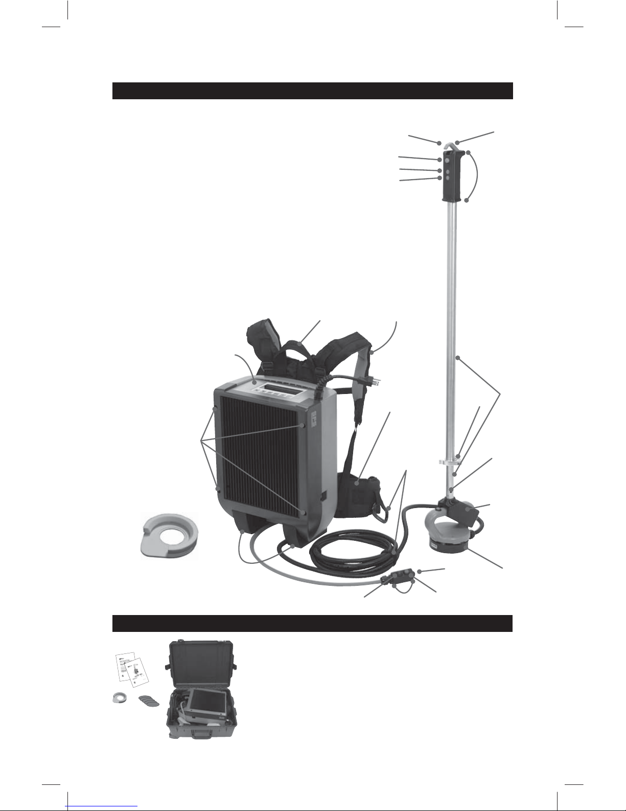
Overview isoweld®3000
4
1
2
1 Inductor
2 Weld button
3 Cable holder
4 Handle
5 Clamping lever for height adjustment
6 Clamping lever for plug connection
7 Display
8 Generator
9 On/Off switch
10 Calibration template
11 Connector
1
2
11
Hand inductor FI-H (optional)
5
7
9
8
6
3
Calibration template
10
11
Standard items supplied isoweld®3000
Induction welding tool, complete
1 Induction welding tool isoweld® 3000
1 Calibration template
1 Set of instruction material
5 Protective foils for inductor
1 Transport box
14
1 Hand-held inductor
2 Flexible handle adaptor allows inductor to be placed on a slanted surface (+/- 5º)
3 Same as magnet pole
4 Turn lock clamp
5 Adjustable Handle
6 Wireless activation switch and handle
7 For thumb action
8 Index finger activation
9 Weld
10 x2
11 OK
12 Cord management
13 Integral waist strap
14 Closed cell foam padded straps
15 Carr y handle
16 Standard generator (same as stand-up tool)
17 4 T20 Screws to remove generator
18 Rubberized feet for impact resistance
19 OK
20 Wired activation switch
21 x2
22 Weld
23 Calibration
Tem plate
Overview isoweld® Backpack
9
10
11
8
7
6
15
14
16
17
18
21
19
20
22
2
3
4
5
12
13
1
Standard items supplied isoweld® Backpack
23
Induction welding tool, complete
1 Induction welding tool
isoweld® Backpack
1 Calibration template
1 Set of instruction material
5 Protective foils for inductor
1 Transport box
1 Hand-held inductor with
cord straps
1 Wired activation switch
1 Adjustable handle
1 Flexible handle adaptor

15
Description of function
Transport
The isoweld ® induction welding tool has been designed for efficient welding of
waterproof membranes with metal stress plates. It is possible to use PVC and
TPO waterproof membranes. The tool has been designed as an upright unit and
therefore allows ergonomic work without excessive fatigue. As soon as the
induction welding tool has been placed over a metal stress plate, the welding
process is triggered by pressing the start button. The welding process ensures
that the waterproof membrane is connected to the stress plate. It is important
that this connection is subsequently weighed down with a magnet.
DANGER!
38 Kg
©
Falling load
Note: NEVER lift or hang the isoweld
®
3000 transport box at the
handles.
38 Kg
NOTICE
Welding with plates without an SFS
stamp may result in roof assembly failure.
USE ONLY SFS MARKED PLATES

16
General
• The points below describe the power requirements for the use of the
isoweld
®
induction machine. These notes are recommendations.
Each job site and its power situation is individual and therefore no
performance guarantee can be given.
• In addition to the recommendations stated in this document, the local
safety and electrical regulations applicable in the country of use must be
observed.
• Consultation of a qualified electrician is advisable.
Electrical safety
• Connect the machine to a socket with a protective ground conductor
Any breakage/disconnection of the protective conductor inside or
outside the tool is potentially dangerous! Use only extension
cables with an ground conductor!
• When the tool is used on building sites, the use of an RCD switch is a
mandatory requirement for personal protection.
Power supply
• Stable power is essential for problem-free operation of the induction
machine.
• A minimum of
- 20 amps per electrical circuit required for countries with 110 volts /
120 volts nominal voltage
- 10 amps per electrical circuit required for countries with 230 volts
nominal voltage
• Maximum one induction machine per circuit, with a recommendation
not to use other devices on the same circuit as the isoweld
®
3000,
isoweld® Backpack.
• Off-load voltage shall not exceed:
- 160 volts for countries with 110 volts / 120 volts nominal voltage
- 240 volts for countries with 230 volts nominal voltage
• On-load voltage at the point of utilization at the machine terminals, with
the machine running, must be higher than:
- 110 volts for countries with 110 volts / 120 volts nominal voltage
- 200 volts for countries with 230 volts nominal voltage
• It is preferable for the induction machine to have its own dedicated
power supply so as to avoid power surges from other equipment, e.g.
drill machines.
Generator
• Use a minimum 5000 watt generator
• Requirements volts and amps see above
• With ground fault circuit interrupter (GFCI)
• Grounding / earthing required
Transformer
• Necessary for use in countries with a nominal voltage of 110 volts if the
voltage at the point of utilization, with the machine running, falls below
110 volts.
• The functionality of the system is only ensured if the transformer
provided by SFS is used.
Power requirements Part 1

17
Start-up isoweld®3000
After opening the container, the body of the unit
can be carefully lifted out. Then the handle of the
tool (see overview) is removed from the transport
box and carefully inserted into the tool.
1. Use fixing screw to secure the
push-fit connection.
2. Adjust the handle to an ergonomic
working height. For this purpose,
release the clamping lever at the
upright and adjust the height.
Re-tighten the clamping lever.
3. Connect the tool to a suitable
power source.
- the cable should not be too long
- suitable conductor cross section
- unroll extension cable
Ensure that the connection is
correctly made.
4. Operate mains switch to turn unit
on.
5. The display shows the input
screen.
The induction welding tool is delivered ready for operation ex-works.
4.
5.
1.
2.
The country-specific regulations must be observed.
3.
Power requirements Part 2
Power cables
• The usable cable thickness and length depend on the power situation on
the job site.
• General rule: The shorter and thicker the cable, the better.
• Recommendations cable thickness:
- for countries with 230 volts nominal voltage: 3 x 1.5 mm
2
- for countries with 110 volts / 120 volts nominal voltage: 12 gauge
cable (3 x 2.5 mm
2
)
• Use only cables appropriate for this application. Check the
cables regularly for damage.
• Outdoors, use only extension cables approved and marked for
this purpose.

18
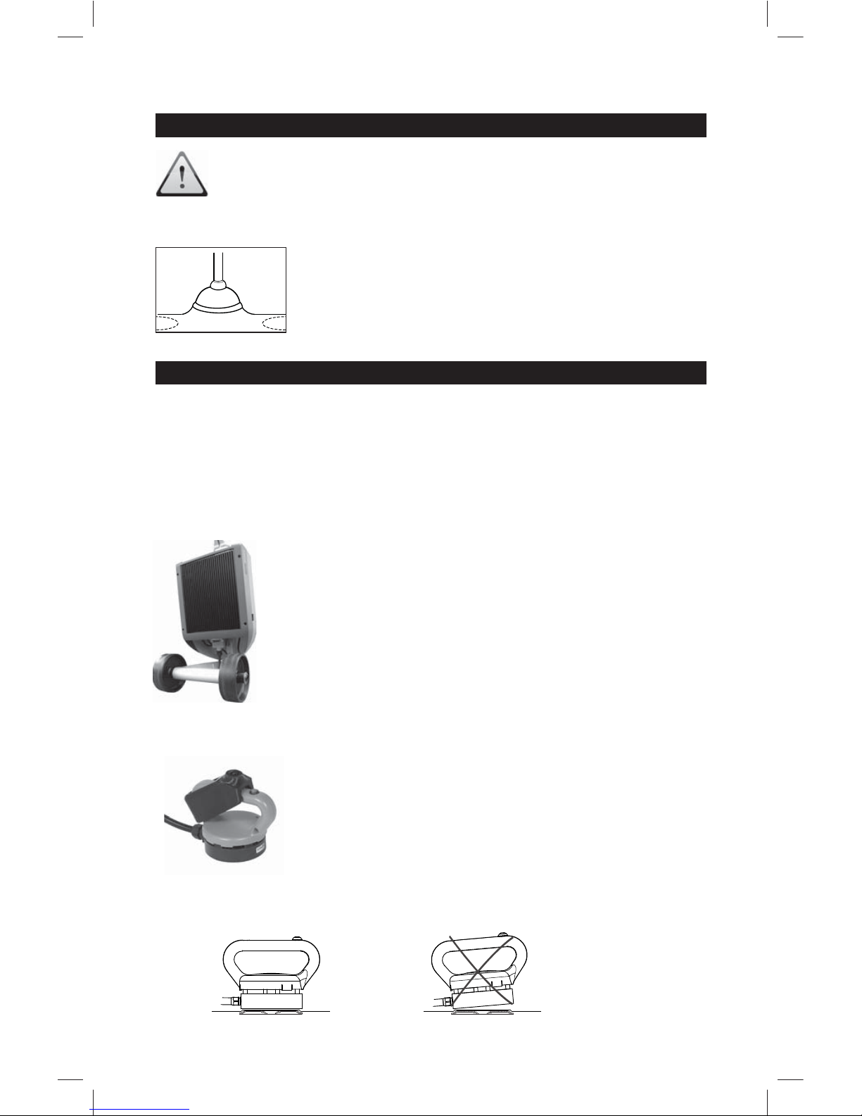
The induction welding tool is delivered ready for operation ex-works.
After opening the container, remove the poles and hand-held inductor, then the
backpack unit can be carefully lifted out. The inductor unit, pole and cords can be
carefully assembled and attached to the tool.
Start-up isoweld® Backpack
1. For use in stand-up mode, connect the handle
adaptor to the hand inductor.
2. Screw the adjustable handle into the top of
the handle adaptor.
3. Press the wireless activation switch/handle
grip on to top of adjustable handle.
4. Adjust the pole with the turning lock clamp to
an ergonomic working height.
5. Open the cover to the hand-held port and
connect the hand-held inductor.
5a. If desired, connect wired activation
switch.
6. Connect the tool to a suitable power source.
- the cable should not be too long
- suitable conductor cross section
- unroll extension cable (diagram page 19)
Ensure that the connection is correctly
made.
©
1
3
5
5a
4
2

19
7. Operate main switch to turn unit on.
8. The display shows the input screen.
9. Perform start-up calibration and test weld
procedures. (see pages 20 & 21)
These procedures must be performed prior
to putting the backpack on.
The country-specific regulations must be
observed.
First, inspect the shoulder straps to
ensure they are not damaged and that they
are firmly connected to the tool body with no
damage or wear at the connection points.
10. After inspection, place your arms through the
shoulder straps to support the backpack on
your back.
Using a tool with damaged straps or
connection points may result in a strap or
connection breaking while in use and the
machine may fall causing personal injury.
If there is any damage noted to the straps or
connections, follow the instructions noted in
the maintenance, service and warranty
section of this manual.
11. Adjust the straps
11a. Adjust the shoulder straps to a good
working fit by adjusting the strap
length at the clip
11b. Attach the chest strap and adjust to
length
11c. Attach the waist strap and adjust its
length so that the machine is
supported by your hips.
12. Use the cord management straps to organize
the power cord and inductor cord for safe,
efficient working.
11 a
11 b
11 c
WARNING!
8
6
7

20
Start-up
Before working with the induction welding tool, the project parameters must
be entered into the display. The parameters required are the waterproof
membrane material and thickness. The following options are available:
For changing the settings, proceed as follows:
The position display is on the choice of the waterproof membrane material
(4first line).
1. Press the button
OK
. ≥ appears and flashes.
2. Press the
L
button or press the M button until the required waterproof
membrane material is displayed.
3. Confirm the selection by pressing the
OK
button. 4 appears.
4. Press the
M
button to go to the waterproof membrane thickness selection.
5. Press the
OK
button. ≥ appears and flashes.
6. Press the
L
or M button to determine the waterproof membrane thickness.
7. Confirm the selection by pressing the
OK
button.
The parameters have now been set and stored.
Note: the settings (parameters) used last will be loaded. It is possible to
either adopt these settings or make new selections of the following settings.
Display examples
Waterproof
membrane
material
Waterproof membrane thickness (mm/mil)
PVC
TPO
0.9-1.1/35-44
1.2-1.4/45-59 1.5-1.7/60-69 1.8-2.0/70-79 2.1-2.3/80-90

21
1. Use the calibration template and place an isoweld® plate into the recess
provided for it (A).
2. Push the calibration template on to the corner of the waterproof membrane
(B).
3. Place the inductor into the calibration device and ensure that it is positioned
correctly (C): the arm (D) to the inductor must be resting in the recess (E)
provided.
4. Press the L or M button to move to CALIBRATION.
5. Press the OK button to open the calibration program.
6. You are now in the calibration program.
7. Press the start button (2).
8. The automatic calibration is completed when there is a beeping sound
for 1 second and the display returns to standard view.
The tool is now calibrated.
Calibration
Ensure that the project parameters are set correctly (waterproof
membrane material and thickness).
Only use material for calibration which has been defined for the current
project.
Calibration process
ABCC
When should the tool be calibrated?
• every morning before starting work
• when moving to another building site
• when working with a different material (PVC instead of TPO or vice-versa,
thinner or thicker waterproof membrane)
• change from 110V to 230V or vice-versa
• change of generator (USA, CAN) or transformer (UK)
D
E
isoweld® 3000 isoweld® Backpack

22
The tool is now ready for operation. (status display
M
lights up green).
SFS recommends that a test weld be carried out
after calibration and before starting installation. Position a stress plate on a level, heat-resistant base
and place a piece of the waterproof membrane to
be used on it. Carry out a test weld (see section on
welding operation). Allow the weld to cool down for
at least 10 minutes. Try to disengage the plate from
the waterproof membrane with the help of pliers.
If the membrane offers a lot of resistance or is destroyed in the process
(after tearing off the stress plate), the weld has been successful. Should
the welded waterproof membrane not have sufficient adhesion to the
stress plate, you need to check the settings (parameters) at the tool etc. For
technical assistance, please contact your service provider. You will find this at
1-800-DEKFAST (335-3278) or www.sfsintecusa.com (US) or
www.sfsintec.ca (CA)
Additional setting options
By pressing the
Menu
button you can set the volume and tone of the signal sound
and the unit of measure (mm/mil).
1. Press the OK button. ≥ appears and flashes.
2. Press the
L
or M button until the required volume is reached.
3. Confirm the selection by pressing the
OK
button.4appears.
4. Press the
M
button to move to the selection of tone or unit of measure.
5. If you want to change these too, repeat steps 1 to 3 accordingly.
6. Press the Menu button in order to return to the standard view.
The parameters have now been set and stored.
Test welding
To set one of these parameters, proceed as
follows:
For example, the position display is on selection
of volume (*first line).

23
Operation: welding
Before carrying out the welding, SFS recommends marking the position
of the stress plates on the top face of the waterproof membrane.
Danger of falling!
Careless working on the roof can lead to falls.
When working on a roof you must wear appropriate safety equipment.
Never use the tool backwards, but always in a forwards direction (see
sections on Hazards and Work position).
It is not permitted to use the isoweld
®
Backpack as a safety harness or
wear the isoweld
®
Backpack over a safety harness, under any
circumstances. Non-observance involves the risk of dealth or injury,
damage to the tool and damage to the processed material.
The induction welding tool and the magnets may have an effect on the
function of cardiac pacemakers and implanted defibrillators. It is possible
that cardiac pacemakers switch to test mode and cause discomfort. It
is possible that defibrillators cease to function. If you are fitted with any
such instruments, you must keep a minimum distance of 20 inches (50
cm) from the inductor (also hand inductor) and the magnets. You must
warn persons fitted with such instruments against coming too close to
the magnets and inductors.
DANGER!
Before installing the waterproof membrane, SFS recommends that the
position of the plates on top of the insulation be checked. Should the
height of any stress plate be incorrect, the height needs to be corrected.
underdriven correct
overdriven
min. 2 mm
W
W
NOTICE
Welding with plates without an SFS
stamp may result in roof assembly failure.
USE ONLY SFS MARKED PLATES

24
Overlaps of waterproof membrane in the area of the stress plate should be
avoided. However, should this situation arise the special function of the welding
tool can be used. Instead of proceeding with normal welding, the
x2
function key
can be pressed. Now proceed as steps 1 to 5.
Important: the
x2
function will only remain active for one weld.
4. The welding process takes approx. 3 to 4 seconds and is terminated
with a double signal sound.
Caution: moving the tool before the welding process has been
completed will always result in an error message and a faulty weld!
5. After completing the welding process, move the tool from the weld
and immediately place a magnet on the welded point. Allow the
magnet to remain for at least 1 minute. The magnet ensures the
necessary pressure and cooling of the stress plate. It is an essential
part of achieving a good weld!
The magnet must be placed within the first 3 seconds after
terminating the welding.
Check the underside of the magnet regularly and remove any metallic
particles.
The magnet must not be rotated during or after positioning if there is
contact with the waterproof membrane. If this instruction is not followed,
the waterproof membrane may be damaged.
6. Move to the next plate position and repeat the search and welding process as
described in steps 1 to 5.
7. At the end of the welding work, switch off the tool at the main switch and
then disconnect from the mains.
Operation: welding
Full overlap Partial overlap Partial overlap
1. Preparing the magnet.
2. Place inductor (1) on stress plate.
3. Press the start button on the handle (3).
a. If the unit has been placed correctly, which means that the cover is suffi-
cient, a continuous signal sound will be heard (1 second) and the status
display
M
changes to orange. The welding process will start automatically.
b. If the unit is not correctly placed, i.e. the cover is insufficient, the inductor
(1) has to be moved until the position is correct (see Fig.1). As soon as the
position is correct, the welding process starts automatically.
c. The tool is equipped with an acoustic search mode which helps the user
to position the inductor precisely on the stress plate. The search mode is
active for max. 15 seconds. When the time limit has
been exceeded, a failure signal sound can be heard
(2 seconds). In this case, acknowledge the signal
by pressing the
OK
button, allow the stress plate to
cool down and restart the welding process (step 1
and subsequent steps).
Fig. 1
25
Working with the hand inductor
Alternatively it is also possible to carry out welds with the hand inductor
(available as an option). This may be appropriate on roof upstands, around
rooflights, on shed roofs etc.
The hand inductor is controlled via the main tool and automatically adopts all
functions and settings from it!
isoweld
®
3000
Checking the welding
If the correct parameters have been selected for the
welding and the recommended test weld has been
successful with positive results, and the instructions in
the operating instructions have been followed, no further
checks of the operation are necessary.
If you are not sure whether certain joints have already
been welded, SFS recommends using the suction pad
provided or a commercially available suction device to carry
out a test. Try to lift the roofing membrane at the point
in question. If that is possible, the joint is still open and
requires welding.
Please note that the underside of the inductor must be positioned
parallel to the top face of the plate!
©
Fig. 2
©
1. Unplug the inductor from the main tool
2. Plug the hand inductor into the main tool (see Fig. 2).
3. Carry out calibration as described in the "Calibration"
section.
4. For further steps, see "Operation: welding" section.
1. Remove the handle adaptor (see Fig. 3) and the inductor
becomes a hand-held tool.
isoweld® Backpack
Fig. 3
©
remove

26
Technical Data isoweld® Backpack
Induction generator:
Workable temperature range: -5 °C to +50 °C
23 °F to 122 °F
Electrical connection: 110V / 230Vw
Power consumption: 1500 Watt
Frequency: 50 Hz / 60 Hz
Tool dimensions isoweld® Backpack:
Size: 457x317.5x203 mm (assembled)
18x12.5x8 in (assembled)
Weight: 10.9 Kg (complete)
24 lbs (complete)
Dimensions of transport box:
Size: 635x508x355.6 mm
25x20x14 in
Weight: 10.4 Kg
23 lbs
Technical data isoweld®3000
Induction generator:
Workable temperature range: -5 °C to +50 °C
23 °F to 122 °F
Electrical connection: 110V / 230V
Power consumption: 1500 Watt
Frequency: 50 Hz / 60 Hz
Tool dimensions isoweld®3000:
Size: 550x520x1100 mm (assembled)
21.6x20.5x43.3 in (assembled)
Weight: 18.5 Kg (complete)
40.8 lbs (complete)
Dimensions of transport box:
L/W/H: 940 x 584 x 610 mm
37 x 23 x 24 in
Weight:15.4 kg
34.0 lbs

27
Error messages
Error message Cause Action
Error 01
voltage problem
Voltage supply is too low for
the tool
Press the
OK
button.
• Choose an electricity circuit
with less load
• Reduce the length of the
supply cable
• Change the supply voltage to
230V (GB, USA, CAN).
Error 02
overload
Max. permitted inductor current
exceeded
Press the
OK
button.
• Restart the welding process
• Should this error message be
displayed repeatedly, please
contact your SFS service
provider.
Error 03
system error
System error
Press the OK button.
• Restart the welding process
• Should this error message be
displayed repeatedly, please
contact your SFS service
provider.
Error 04
system too hot
Tool has heated up too much
Press the OK button.
Turn off the tool at the main switch
and allow to cool down.
Error 05
welding not
complete
Required welding temperature
not reached
Press the OK button.
Allow the weld point to cool down
and restart welding process.
Error 06
no plate
Max. search time exceeded
Press the OK button.
• Check that there is a stress
plate
• Allow the weld point to cool
down and restart welding
process.
• Should this error message
be displayed several times,
recalibrate the tool.
Error 07
plate lost
Inductor has been accidentally moved during the welding
process
Press the
OK
button.
Allow the weld point to cool down
and restart welding process.
Error 08
temperature
sensor
Temperature sensor defective
Press the
OK
button.
Contact your SFS service provider.
Error 09
no calibration
The program used has not been
calibrated
Press the
OK
button.
Calibrate the tool in accordance
with the "Calibration" section.
Error 10
mains voltage
Permissible input voltage too
low
Press the OK button.
• Choose an electricity circuit with
less load
• Reduce the length of the supply
cable
• Change the supply voltage to
230V (GB, USA, CAN).

28
• Regularly clean the tool using a soft cloth and mild cleansing solution.
• Protect the tool from moisture and dirt.
Avoid contact between any plastic components of this equipment and
solvents, oils, gasoline, petro-based products, acids or other harsh
chemicals; they can damage the plastic components, which could result in
personal injury.
Electrical maintenance
On principle, electrical equipment may only be serviced and repaired by qualified
technicians.
Backpack Straps
If there is damage or wear to the straps or connection points, the strap or
connection may break during use and the machine may fall causing personal
injury.
If the straps are determined to be worn but the connection points show no signs
of wear or damage, remove the straps by removing the eight (8) T25 attachment
screws and loosening the upper tie straps. Replace the straps by reinserting the
eight (8) T25 screws through a new strap and re-attaching the upper tie straps to
the equipment. Use only straps intended for use with this equipment.
Maintenance, service and warranty
Disposal
The tool must not be disposed of with household refuse.
Dispose of the tool at the disposal points provided for this type of
equipment in accordance with the national or local regulations.
The tool must be disposed of in accordance with the European
Directive 2012/19/EU (WEEE). This directive regulates the return and
recycling of waste equipment within the EU.
NOTICE
Welding with plates without an SFS
stamp may result in roof assembly failure.
USE ONLY SFS MARKED PLATES
WARNING!
(4) T25
(4) T25
Upper tie
straps
29
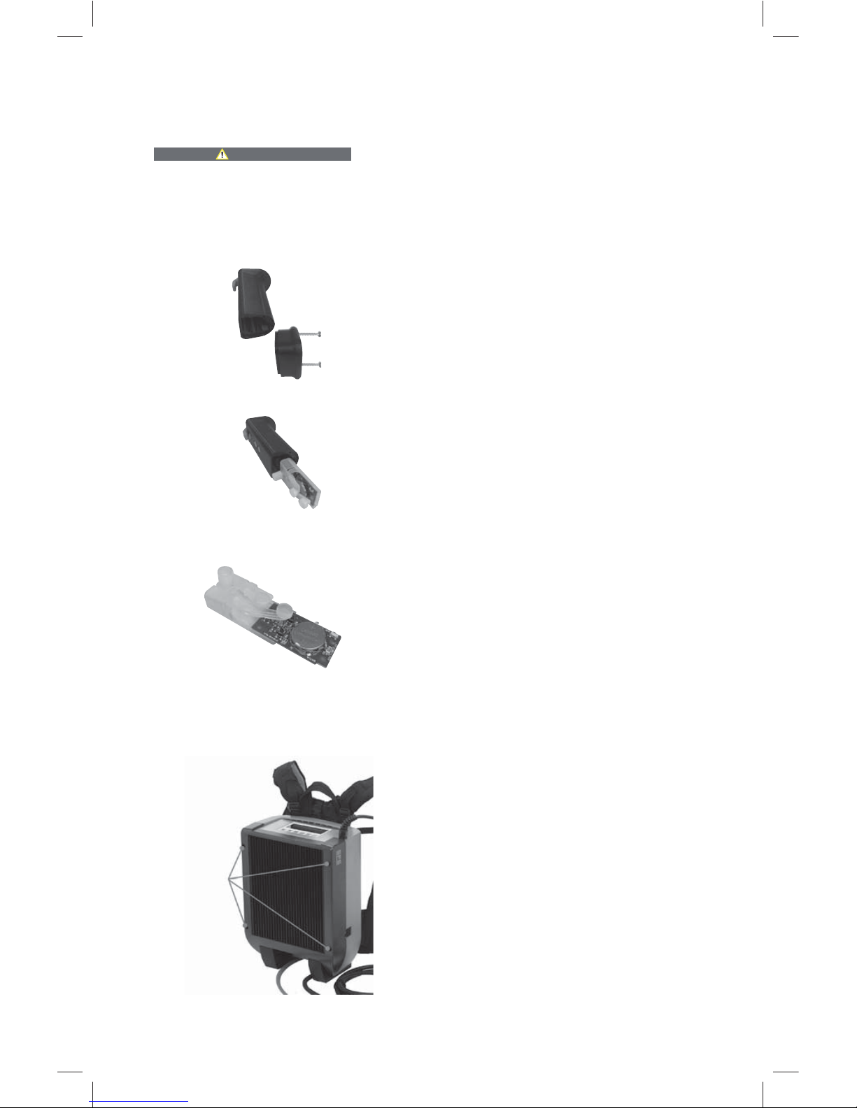
Replacing the Battery in the Wireless Activation Switch:
1. Remove the two (2) T10 screws from
the base of the switch and remove the
lower cap
2. Reach in and slide out the wireless
switch module
3. Slide the switch board out slightly from
its housing in order to access the
battery
4. Replace the 3V CR2032 Lithium Cell
Battery with a new one and recycle the
old battery
Reprogramming the Wireless Activation Switch:
1. Remove the four (4) T20 screws
from the gray plastic housing in
order to access the generator
1
2
3
If there is damage or wear to any of the connection points, contact SFS tool
service or an authorized repair shop.
Using a tool with damaged straps or connection points may result in a
strap or connection breaking while in use and the machine may fall causing
personal injury.
WARNING!
1
4 screws
to remove
generator

30
2. Remove the elastic strap that runs
across the top of the generator so
that you can access the side of the
generator adjacent to the Backpack
harness
3. Rock the generator forward from the
Backpack harness in order to access
the reprogramming switches
4. Press the “Start” button of the
reprogramming switches and hold
for three (3) seconds
5. 5 While still holding the “Start”
button on reprogramming switch
panel, single click the “Weld” (i.e.
“Start”) button on the wireless
activation switch
6. Release the “Start” button on
the reprogramming switch panel.
The “Weld” button on the wireless is
now programmed to work with this
generator
7. Press the “OK” button of the
reprogramming switches and hold
for three (3) seconds
8. While still holding the “OK” button
on reprogramming switch panel,
single click the “OK” button on the
wireless activation switch
Release the “OK” button on
the reprogramming switch panel.
The “OK” button on the wireless is
now programmed to work with this
generator
2
©
3
©
4
©
7
©
5
©
8
©
Weld
OK

31
9. Press the “x2” button of the
reprogramming switches and hold
for three (3) seconds
10. While still holding the “x2” button
on reprogramming switch panel,
single click the “x2” button on the
wireless activation switch
Release the “x2” button on
the reprogramming switch panel.
The “x2” button on the wireless is
now programmed to work with this
generator
Service
For technical information, please contact SFS tool service.
Warranty
The isoweld® 3000 and isoweld® Backpack must be registered
within 30 days of purchase. To protect your investment and
register the tool, go online at:
www.sfsconstructionna.com/toolregistration/
1. This induction welding tool has been carefully checked, tested and subjected
to strict quality control.
2. We warrant the rectification, free of charge, of defects on the induction
welding tool that occur within 24 months of the date of sale or 200,000 welds
to the end user and that are due to a material or manufacturing fault. Individual
special regulations apply to the conditions of the warranty in some countries.
We reserve the right to rework defective parts or replace them with new ones.
The ownership of the replaced parts is transferred to us.
3. Improper usage or handling, as well as the opening of the tool by unauthorised
repair centers, will render void any claims under the warranty. The warranty
excludes the following: damage caused by penetration of water or other
liquids, a cut or damaged cable, damage to the electronics and mechanical
damage caused by overloading. Likewise excluded are wear parts such as the
induction coil, gliding foil etc.
4. Claims under the warranty can only be accepted if defects (as well as
transport damage) are notified without delay. The statute of limitations is not
automatically extended by the provision of service under the warranty.
5. In order to make a claim under the warranty, the took registration must be on
record, as noted above. To make the claim, contact SFS at:
US: 1-800-DEKFAST (335-3278)
6. Any further claims by the purchaser – in particular the right to rescission,
price reduction or claims for damages – are excluded due to the warranty
obligations undertaken by us, as far as permitted by the law.
9
©
10
©
x2

32
We SFS intec AG
Division Construction
Rosenbergsaustr. 10
CH-9435 Heerbrugg
hereby declare that the products in the series
Type: isoweld® 3000, isoweld® Backpack
comply with all the essential requirements of the following directives:
2014/35/EU EU Low Voltage Directive
2014/30/EU EU EMC Directive
Person authorised to compile the technical documentation as per Annex VII A of
the directive 2006/42/EC:
Daniel Gasser
SFS intec AG
Rosenbergsaustr. 10
CH-9435 Heerbrugg
Daniel Gasser
Head of Research and Technology
SFS intec AG
In the case of modification of the tool this declaration and the warranty will be
rendered void.
We reserve the right to make modifications!
Declaration of conformity
7. The purchaser is entitled, at the purchaser’s choice, to a price reduction
(reduction of the purchase price) or rescission (annulment of the contract of
purchase), if we are unable to rectify within a reasonable period any defects
that may occur.

33
System components 35
Deciding on installation strategy 36
Preparing the roof for fastening 36
Measuring and marking fastening points 36
Fixing the stress plates 37
Rolling out the waterproof membrane 38
Marking the fastening points 38
Preparing the induction tool 39
Welding the membrane at the fastening points 40
System isoweld
®
3000 and
isoweld
®
Backpack
Installation Instructions

35
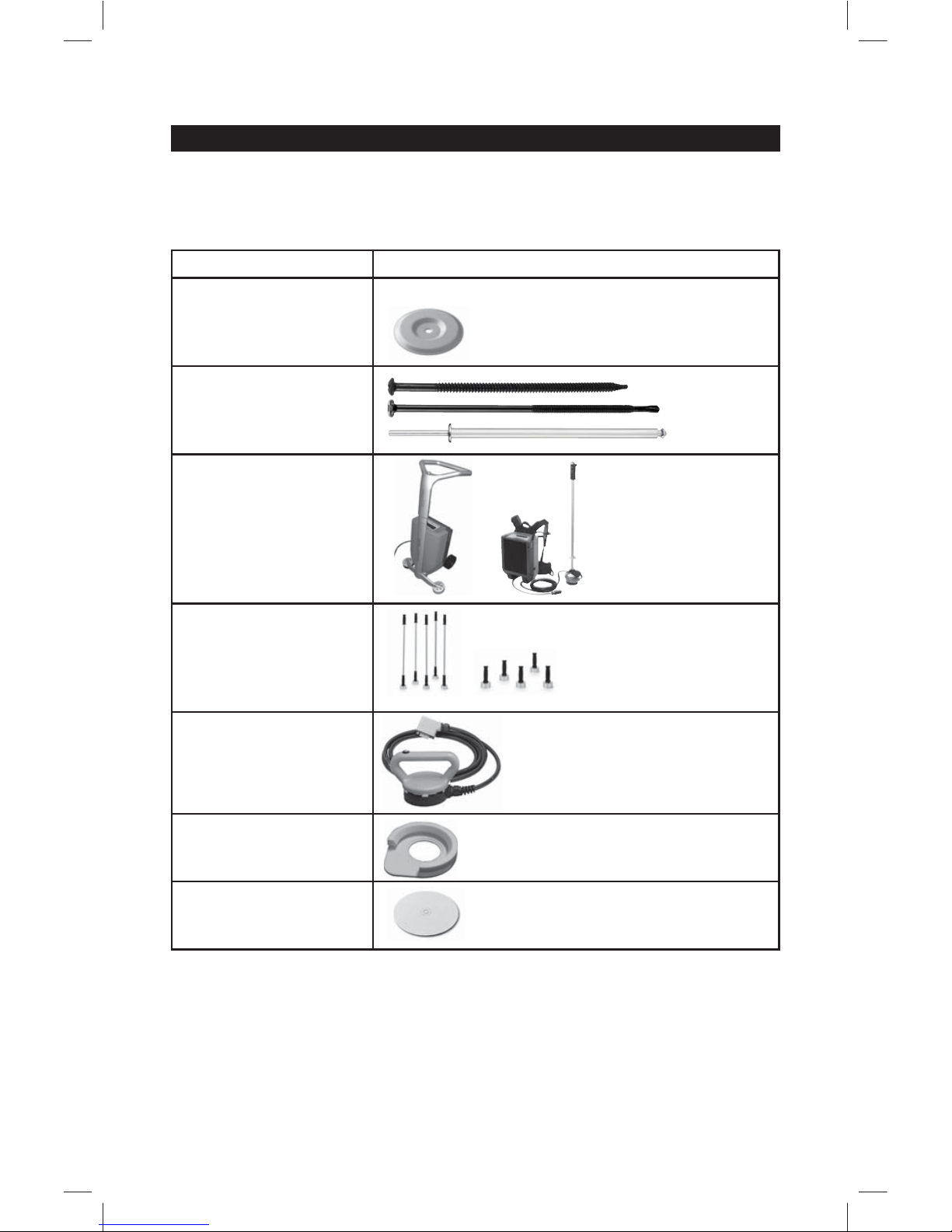
Ensure that you have all required system components at your disposal.
System components
System components Product identification
Stress plate
FI-P
Fastener
#15 Dekfast
#12 Purlin
TPR-L Peel Rivet
Induction tool
isoweld
®
3000
isoweld
®
Backpack
Magnets
FI-Magnet
Hand inductor
FI-H
Calibration template
Pad for EPS/XPS
application
FI-Pad

36
1. Deciding on installation strategy
2. Preparing the roof for fastening
3. Measuring and marking fastening points
• Familiarize yourself with the results of the wind load calculation and decide
on the procedure for the installation.
• Consider how best to deploy personnel, materials and equipment. In this
way you will achieve a fast, correct and efficient installation.
• Prepare the roof for laying out the waterproof membrane (e.g. prepare
substrate, vapor barrier, thermal insulation, fleece etc.).
• It is important to observe local regulations and manufacturers’ instructions.
We recommend that only so much roof area be prepared as can be
fastened and welded on the same day.
• Before rolling out the waterproof membrane, steps 3 and 4 have to be
carried out.
Measure the locations of the fastening points in accordance with the wind load
calculation and mark these on the prepared roof surface using e.g. a chalk line.

37
4. Fixing stress plates
underdriven
correct overdriven
min. 2 mm
W
W
• Fix the stress plates in accordance with the wind load calculation.
• Use the specified fastener.
Only set as many stress plates as can be welded on that day.
• Ensure that the stress plates are dry and clean, both in storage and during
and after installation.
• When installing on EPS/XPS thermal insulation, an FI-Pad must always be
used, even when a fleece is placed between the EPS/XPS thermal insulation
and the waterproof membrane.
• The FI-Pad must be placed directly under the stress plate.
FI-Pad
NOTICE
Welding with plates without an SFS
stamp may result in roof assembly failure.
USE ONLY SFS MARKED PLATES
• Check the setting depth of the stress
plates (see figure below).
• The stress plates must be set parallel to
the surface.
Incorrectly installed stress plates
adversely affect the quality of the weld.

38
6. Marking the fastening points
5. Rolling out the waterproof membrane
• Install the waterproof membrane in accordance with the membrane
manufacturer’s instructions.
Compared to seam fixing systems, the isoweld
®
system makes it
possible to reduce the overlap of the waterproof membrane.
• Overlaps of the waterproof membrane in the area of the stress plate should
be avoided. See also the isoweld
®
3000 / isoweld® Backpack operating
instructions.
• Ensure that the underside of the waterproof membrane is dry.
• Use the isoweld
®
magnets (turning clockwise) or other suitable aids to mark
the top of the waterproof membrane above the stress plate.
Careful marking contributes significantly to a fast welding process.
Clean magnets from debris on a regular basis to prevent membrane
damage.

39
7. Preparing the isoweld® 3000 / isoweld® Backpack induction tool
Prepare the isoweld
®
3000/ isoweld® Backpack induction tool for
welding in accordance with the separate operating instructions.
This includes in particular:
• unpacking and assembling the magnets
• unpacking and assembling the tool
• switching the tool on
• entering the waterproof membrane material
• entering the waterproof membrane thickness
• calibration
• test welding

40
11.
12.
13.
14.
15.
16.
19.
18.
17.
20.
1.
2.
3.
4.
5.
6.
7.
8.
9.
10.
1.
2.
3.
4.
5.
6.
9.
8.
7.
10.
8. Welding the membrane at the fastening points
Proceed with the welding process in accordance with the isoweld
®
operating instructions.
For an efficient process, we recommend the following procedure:
1. Place at least 10 magnets to the right of the points to be welded (A).
2. Weld the first of these points (B).
3. Place the magnet on to this fastening point within 3 seconds of completing
the welding (C).
4. Proceed to weld the following points 2 to 10 as described in steps 2 and 3
(D).
5. Move the isoweld
®
induction tool to the starting point of the next line (point 11
(E).
6. Proceed to weld points 11 to 20 of the line on the left, as described in steps
2 to 4.
7. etc.
1.
2.
3.
4.
5.
6.
9.
8.
7.
10.
1.
2.
3.
4.
5.
6.
9.
8.
7.
10.
1.
2.
3.
4.
5.
6.
9.
8.
7.
10.
A
B
C
D
E

41
Fast and exact positioning of the magnet is a prerequisite for good
welds.
The magnet must not be rotated during or after positioning if there is
contact with the waterproof membrane. If this instruction is not followed,
the waterproof membrane may be damaged.
Clean magnets from debris on a regular basis to prevent membrane
damage.
• Ensure that all fastening points have been properly welded.
• Should you be uncertain about whether some welds have completed
properly, SFS recommends testing with a commercially available suction
pad.
See also isoweld
®
operating instructions.


© 2018 SFS, iFR, 902047, 03/18, 2.0 Mat. No. 1586027
Created in United States / Right of modifications reserved
SFS Group USA, Inc.
Division Construction
1045 Spring Street
PO Box 6326
US-Wyomissing, PA 19610
800 234 4533
T +1 610 376 5751
F +1 610 376 8551
us.construction@sfsintec.biz
www.sfsintecusa.com
SFS - Canada
40 Innovation Drive
Dundas, ON L9H 7P3
T +1 905 689 5401
ca.info@sfsintec.biz
www.sfsintec.ca
 Loading...