

User handbook
Valid for instruments with version 04.xx
SOCIÉTÉ FRANÇAISE D'ÉTUDES
ET DE RÉALISATIONS ÉLECTRONIQUES
Tél. 04 78 16 04 04 - Fax 04 78 16 04 05
Tel. Intern. 33 4 78 16 04 04 - Fax Intern. 33 4 78 16 04 05
SFERE : Route de Brindas Parc d’activité d’Arbora N°2
69510 SOUCIEU EN JARREST FRANCE
''**11 $$&&
The friendly
interface
DIGITAL PANEL METERS
programmable ±10 000 points
DIGINORM
®
SFERE - DGN 75AC TA IN/18 v.04 - A 04/04 - Any data in this documentation may be modified without prior notice.

S
Summary
1 . PRESENTATION p2
2 . SPACE REQUIREMENTS p3
3 . WIRING p4
4 . PROGRAMMING p5
4.1 Communication with the instrument p5
4.2 Orientation through the programming p5
4.3 Main menu p5
4.4 Programming menu p6
4.4.1 - Programming of the input p6
4.4.2 - Programming of the display p7
4.4.3 - Programming of the analog output p7
4.4.4 - Programming of the digital output p8
4.4.5 - Programming of the LOGIC inputs p8
4.4.6 - Programming of the relay outputs p8
4.4.7 - Programming of mode safety p9
4.4.8 - Programming of the brightness, the bargraph p9
and the displays
4.4.9 - Programming exit with or without saving p10
4.5 Input features and programming limits p10
4.5.1 - Automatic or manual caliber p10
4.5.2 - Choice of the current caliber p10
4.5.3 - Choice of the voltage caliber p10
4.5.4 - Choice of the CT ratio p10
4.5.5 - Choice of the VT ratio p10
4.5.6 - Programming of the LOGIC inputs p11
4.6 Output features and programming limits p11
4.6.1 - Analog output p11
4.6.2 - Digital output p11
4.6.3 - Relay outputs p11
4.6.4 - Safeties p12
4.6.5 - Display features p13
4.7 Reading of the configuration p13
4.8 Access code p14
4.9 Programming of a new access code p14
4.10 Functions accessible in the main menu p14
4.10.1 - Display simulation p14
4.10.2 - Analog output simulation p15
4.10.3 - Menu CLEAr :
Deleting of recorded alarms p15
5 . FUNCTIONS DIRECT FROM THE DISPLAY p15
5.1 Functions which require pressing only 1 key p15
a / Display of the minimum value p15
b / Display of the maximum value p15
c / Display switching p15
d / Deleting of maximum and minimum values p15
5.2 Functions which require pressing several keys p16
5.2.1 - Automatic setting of the cut-offs p16
5.2.2 - Visualisation of the measure unit p16
5.2.3 - Visualisation and setting of the alarm setpoints p16
5.2.4 - Modification of the display resolution p16
6 . ERROR MESSAGES p16
7 . GENERAL WARRANTY TERMS p16
8 . LEXIQUE p17
9 . ANNEXE : MODBUS p19
9.1 Table of the modbus addresses of the measures p19
9.2 Table of the adresses of the measure units and points p19
9.3 Description of born modbus functions p20
9.4 Reading in double integer format p20
9.5 CRC 16 calculation algorythm p21

S
The series DGN 75AC offers a whole range of high accuracy programmable panel meters. Each instrument is equipped on its front face with a
five 14mm high red digits display, whose brightness suits applications in
industrial control rooms perfectly.
They allow display, control and transmission of data from alternating voltage, alternating current and of frequencies from alternating signals.
•
DGN 75AC
Measurement of an alternating voltage, an alternating current and of the
frequency of an alternating signal.
• 2 programmable voltage calibers : 150V and 500V
Un = 150 VAC and 500 VAC
Overstepping 1.2 Un
• 2 programmable current calibers : 1A and 5A
In = 1.2A and 6A
Overstepping 1.2 In
Automatic caliber on 0-500V, 0-5A possible
• Voltage overload
permanent : 750 V
during 10s : 1000 V
• Current overload
permanent : 10A
during 10s : 50A
• Frequency : 45 Hz to 65 Hz
• Accuracy rating :
0.2 % voltage / current (at 25°C)
• Measure cycle
55 ms
• Display :
3 magnitudes can be programmed for a display accessible simply by
pressing 1 key.
11.. PPRREESSEENNTTAATTIIOONN
AAVVAAIILLAABBLLEE OOPPTTIIOONNSS
: (specify on order)
Insulated analog output
: A
Active or passive current, or voltage output.
Programmable scale ratio with enlarging effect.
Relay output
: R or R4
2 or 4 relays :
Setpoint relays :
mode setpoint or mode window.
Latching function.
Time delay and hysteresis adjustable on each setpoint.
Alarm messages
Insulated digital output : N
RS 485 2 wire, protocole MODBUS-JBUS.
LOGIC input 2 insulated LOGIC inputs with programmable functions
Display hold,
Min. and max. zero reset
Bargraph
: (16 led display) : B
Allows a quick evaluation of the measured value
variations.
Programmable scale factor
Possibility to programme 3 bargraphs (1 for each
displayed parameter)
S
Protection :
Front face : IP 65
Case : IP20
Terminals : IP 20
Case
:
Self-extinguishing casing of
black UL 94 V0 ABS.
Connectors
plug-off connectors on
rear face for screwed connections
(2.5mm², flexible or rigid)
Display
: ±10 000 points (14 mm)
Electroluminescent red (green optional)
4 alarm leds
-2 000 / +10 000 points (20 mm)
(consult)
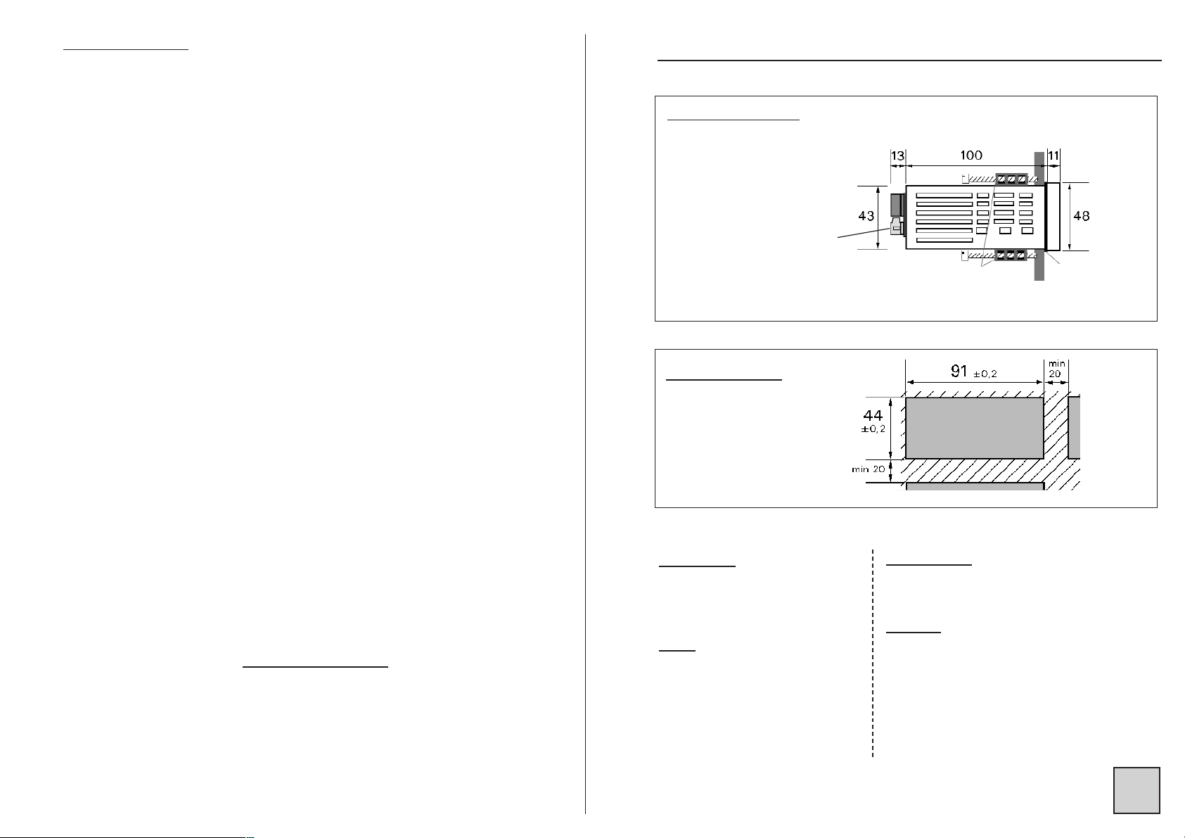
22.. SSPPAACCEE RREEQQUUIIRREEMMEENNTTSS
Case dimensions : (with terminals)
96 x 48 x 124 mm
Panel mounting
cut out 44 x 91 mm
external
seal
Mounting panel
max. thickness 30
case
tightenings
Terminals
General features
• Input impedance ≥ 1 MΩ for the voltage inputs
< 0.2 VA for the current input
• Common mode rejection rate : 130 dB
Serial mode rejection rate : 70 dB 50/60 Hz
• Thermic drift < 200 ppm/°C
• Insulation : Input / Power supply : 2.5 kV eff. 50Hz-1min
Input / Output : 2.5 kV eff. 50Hz-1min
• Power supply : (specify on order)
2 Versions : High Voltage or Low Voltage
High Voltage : 90...270 V
AC and 88 ...350 VDC 50/60/400 Hz
Low Voltage : 20...53 V
AC and 20...75 VDC 50/60/400 Hz
• Power draw : 5 W max. 8 VA max.
• Complies with standards EN 50081-2 on emissions and EN 50082-2;
on immunity (in industrial environment)
EN 61000-4-2 level 3, EN 61000-4-3 level 3,
EN 61000-4-4 level 4, EN 61000-4-6 level 3.
CE marking according to Directive EMC 89-336
• Environment :
Operating temperature : -5° to 55°C
Storage temperature : -30° to 80 °C
Relative dampness : 80% annual average.
S
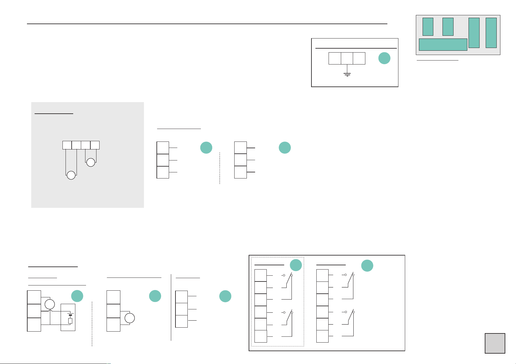
33.. WWIIRRIINNGG
20
21
22
1 2 3 4 5 6 7 8 9
23
24
25
26
27
28
29
30
31
32
33
34
35
36
37
C
E
D
B
A - inputs
Location of terminals
(view of case rear side)
Wiring recommendations
The input network may carry significant disturbances, and they may disturb the complete chain. In order to avoid
this, the disturbance immunity can be made significantly better by respecting following rules :
- do not connect close to each other : the input network and the DGN 75AC power supply wires,
- do not connect close to each other : the input network and all the DGN 75AC output wires,
- use for all DGN 75AC outputs shielded cables connected to the ground on both extremities.
23
24
25
TOR 1
TOR 2
COM
LOGIC INPUTS
(options)
2 channels
32
33
34
TOR 1
TOR 2
COM
2 channels
RU
C E
1 2
3
-
~
~
+
AC
DC
OUTPUTS
(options)
POWER SSUPPLY
26
27
28
29
30
31
2 RELAYS
T1
C1
R1
T2
C2
R2
T : ON
C : Common
R : OFF
0-4/20mA active
ACTIVE CURRENT
0-4/20mA passive
external source 30 V max.
VOLTAGE
PASSIVE CURRENT
32
33
34
35
36
37
4 RELAYS
20
21
22
DIGITAL
Data link RS 485
B
A
COM
T3
C3
R3
T4
C4
R4
+ -
23
24
25
mA
RU
+
23
24
25
V
Lr
+
-
CC
E
D
B
A
5 6 7 8
I
U
0/1 A
AC
0/5 AAC
0/150 VAC
0/500 VAC
INPUTS
and
S
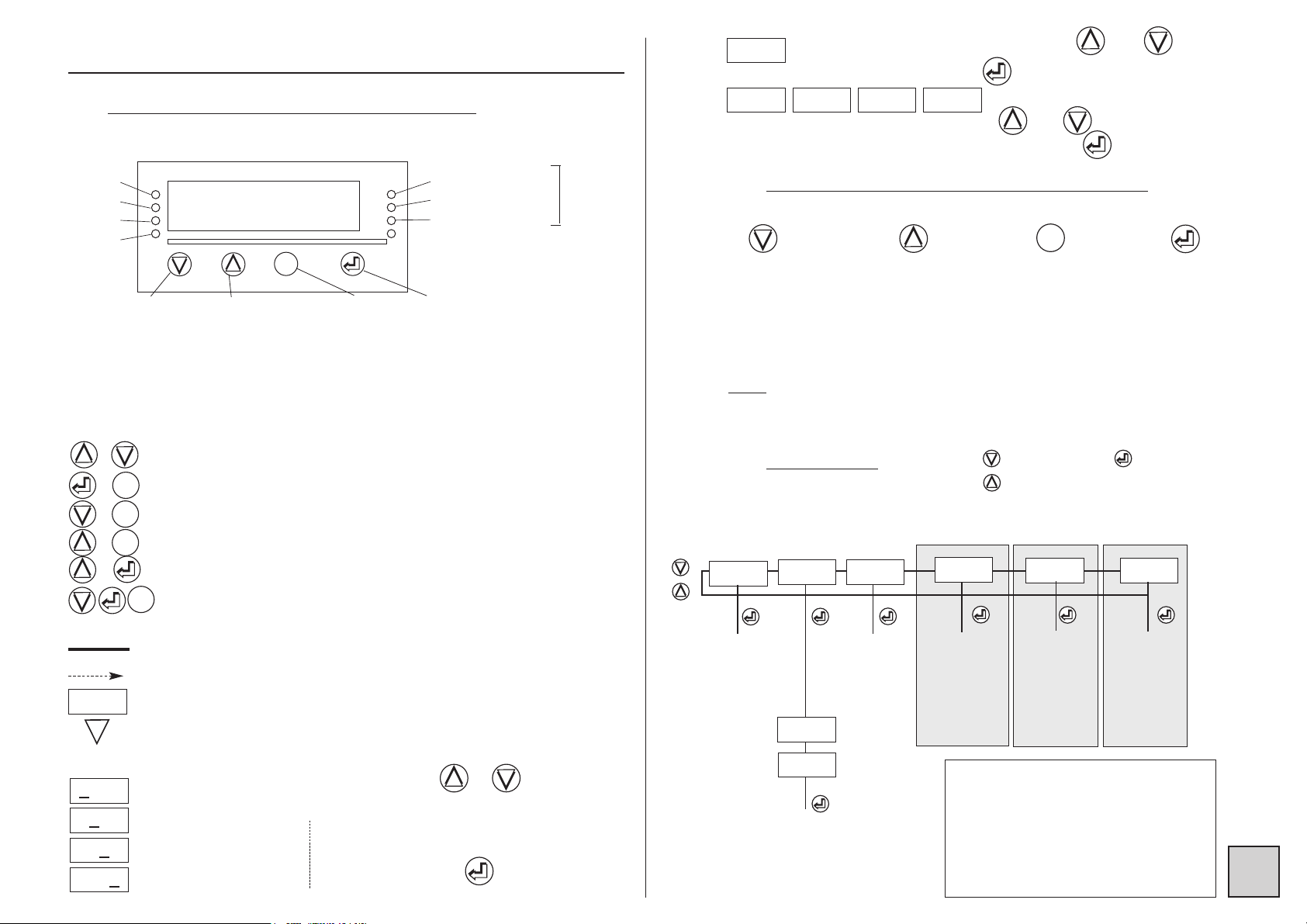
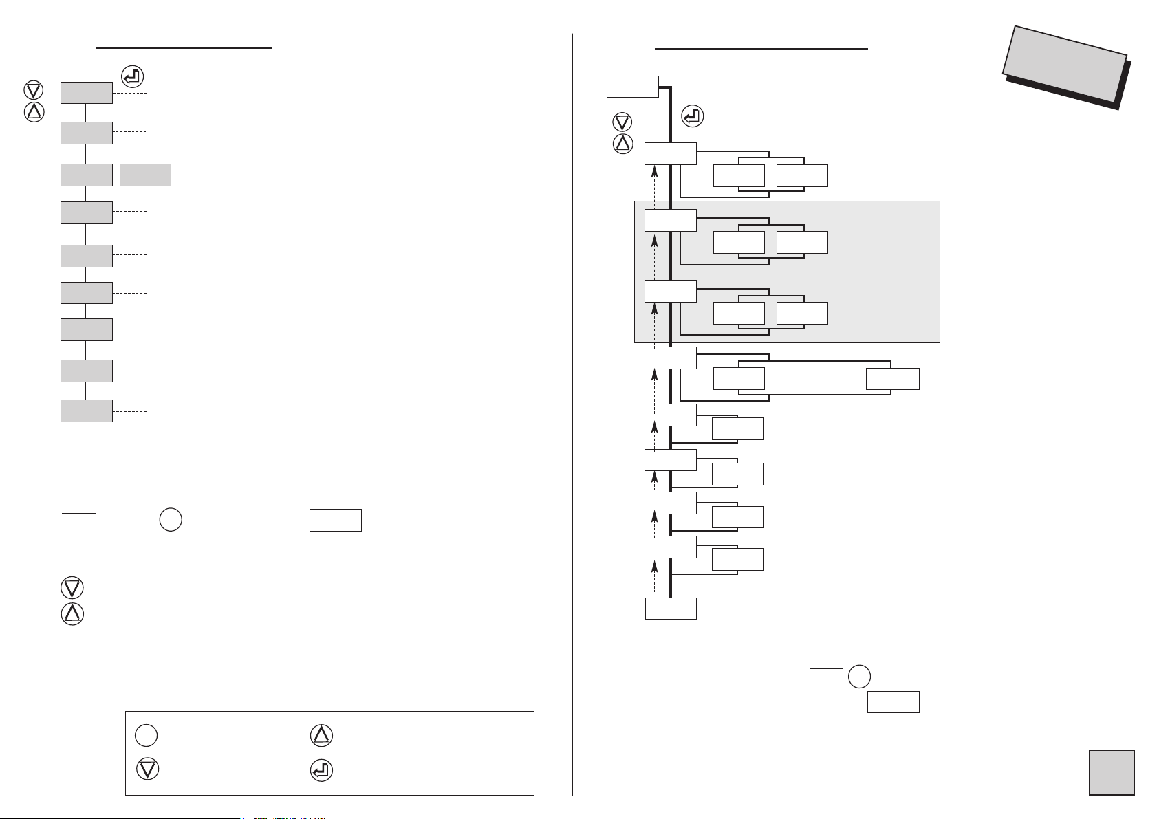
44.. PPRROOGGRRAAMMMMIINNGG
4.1 CCommunication wwith tthe iinstrument
Several functions can be accessed from measure :
4.3 MMain mmenu
4.2 OOrientation tthrough tthe pprogramming
Dialogue is ensured by 4 keys located on the front face.
Move through
menus : downwards, or
decrease the value
shown
Validation of
the displayed
parameter, or
access to a
sub-menu
Exit from a submenu to access
next menu /
access to the
programming
exit menu
Note
: In mode programming, the instrument will automatically revert to
measure with the former configuration if no key is pressed during 1min.
Move through
menus : upwards,
or increase the
value shown
Alarms
Led 1
Led 2
Led 3
Led 4
Functions
Indication display 1
Indication display 2
Indication display 3
Display of the min.
value (p15), or pass on
to next displayed
parameter (long
pressing > 3s)
Display of the max.
value (p15), or pass
on to next dislayed
parameter (long
pressing> 3s)
min. and
max. zero
reset p15
Access to
main menu
p5
Mode configu-
ration reading
If code correct,
access to the
programming
menu
Entering of the access code.
This access to the programming
menu is protected by a 4-digit
code.
The code on factory exit is 0000
(to modify this code,
Simulation
of the ana-
log output
Authorized by
access code
Deleting of
recorded
alarms
Measure
display
M
M
MM
MM
rEAd
ProG
CodE
8 888
GEnE. CLEAr
«
«
«
«
«
Programming
of the access
code
Display
simulation
Authorized by
acess code
(relay/ analog
output
(analog
output)
(relay output)
P.CodE
SIMUL
«
«
scroll
menus
vertical
move
(see p13)
see p14)
(see p15)
(see p15)
(see p14)
(see p14)
(see p6)
6..520
11 1100 33 1100 66 1100 99
and
and choice of the decimal point by
validate this choice by
and choice of the unit by
validate this choice by pressing key
Stick the
unit labels
on the leds
Further functions can be reached by pressing several keys
simultaneously :
Automatic voltage cut-off setting; (see p16)
Automatic current cut-off setting; (see p16)
Visualisation of the measure unit; (see p16)
Visualisation and setting of the alarm setpoints; (see p16)
Modification of the display resolution; (see p16)
Recording of the current display as the display which
will appear on setting on tension.
Reading convention :
Move through the main menu
Revert to previous menu
Blinking display : awaiting validation or setting
Alternate information display
Entering of a parameter :
first start by increasing or decreasing
the 1st digit and the sign : from -9 to +9.
The 2nd from 0 to 9.
The 3rd from 0 to 9.
The 4th from 0 to 9.
+
66
888
65588
65228
652
00
«
Between each entering, validate
the cipher with key
M
M
+
+
M
M
+
M
M
M
M
+
+
S
M
M
InPut
InPut
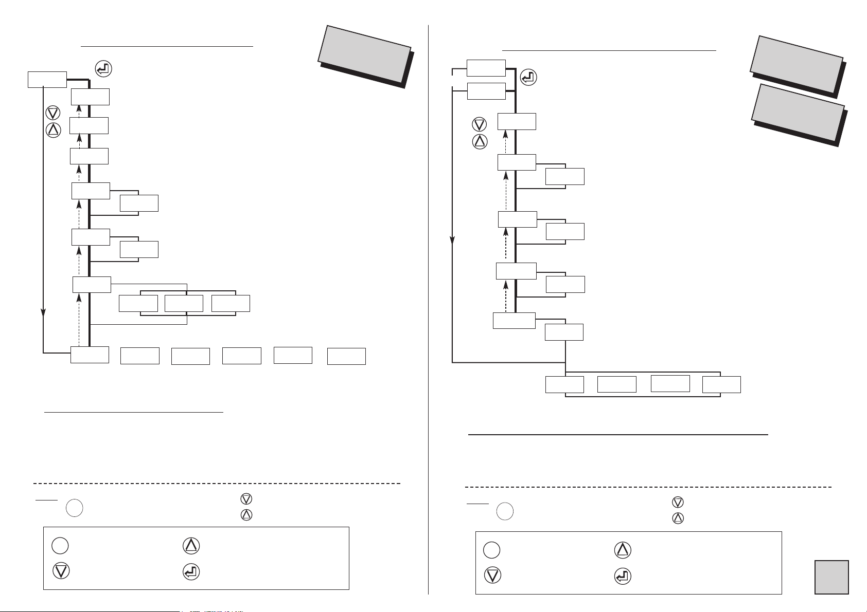
4.4 PProgramming mmenu
(according to options)
4.4.1 Programming of the input
dISPL.
OUt.MA OUt.U
JbuS
tor
rELAY
SECU
Pr.diS
SAvE
SAvE
Access to the programming of the network type, CT
and VT ratios ...
Access to the programming of the 3 displays, the
voltage and current cut-off, filtering
Access to the analog output programming
(option analog output)
Access to the communication parameters
(option digital output)
Access to the programming of the LOGIC inputs
(option LOGIC inputs)
Access to the relay programming (2 or 4 relays)
(option relay outputs)
Access to the programming of the relay outputs in case
of error self-diagnosis
Access to the display programming :
Leds, Bargraph, Display brightness
Access to the programming exit menu with or
without recording the configuration
choice of the current caliber
if auto caliber
caliber 1A caliber 5A
enter CT primary value (decimal point + unit)
or full display scale for the current input
Note :
⇒ Press key to revert to menu
⇒ In mode programming, the instrument will automatically revert to
measure with the former configuration if no key is pressed during 1min.
Move through menus / choice
M
M
diSPL.
Note :
Press to revert to
menu
or
«
Pri.tc
«
8.888
1A
5A
enter CT secondary value
or current input full scale
«
SEC.tc
«
005.0
«
p6
p8
p8
p9
p9
p10
p8
p7
p7
«
CAL1
InPut
choice of the voltage caliber
caliber 500V
150
500
«
«
«
choice du calibre
manual automatic
MAnu
Auto
«
«
CAL
«
«
CALU
Sin
dEFOr.
«
«
SiGnA.
«
enter VT primary value (decimal point + unit)
or full display scale for the voltage input
«
Pri.tP
«
8.888
enter VT secondary value
or voltage input full scale
«
SEC.tP
«
500.0
Downwards move /
decrease
Validation / Vertical move
Menu exit /access
Upwards move /
increase
M
M
caliber 150V
diSPL.
sinusoidal
signal
deformed signal
(eg. : phase angle)
S
4.4.2 Programming of the display
diSPL.
«
diSP.2
«
diSP.3
«
Cut.I
choice of display parameter n°1
choice of display parameter n°2
choice of display parameter n°3
enter current cut-off from 1.0% to 15.0% in manual caliber
from 0.2% to 15.0% of caliber 5A
in auto caliber
according to options
003.0
«
FiLt.
«
OFF
«
1
«
2
Out.MA
Out.U
JbuS
tor
rELAY
SECU
or
or
or
or
or
M
M
Note :
Press to go on to next menu
Move through menus / choice
«
diSP.1
«
dISPL.
current cut off
«
Cut.U
enter voltage cut-off from 1.0% to 20.0% in manual caliber
from 0.3% to 20.0% of caliber 500V
in auto caliber
003.0
voltage cut off
choice of the filtering
no filtering
Choice of the display parameters
U, I, FrE.
U
: voltage
I : current
FrE. : network frequency
Downwards move /
decrease
Validation / Vertical move
Menu exit / access
Upwards move / increase
M
M
4.4.3 Pro
gramming of the analog output
«
-88.88
«
PAr.dS
Out.MA
Out.U
analog output down scale
choice of the parameter associated
with the analog output
analog output full scale
entering of the parameter value corresponding to the
output down scale (decimal point + unit)
entering of the parameter value corresponding to the
output full scale (decimal point + unit)
00.00 < x < 22.00 (mA)
00.00 < x < 11.00 (V)
see also the output features p11
according to options
JbuS
tor
rELAY
SECU
or
or
or
(4)
(4)
(4)
Option aanalog ooutput
«
-88.88
«
-88.88
«
-88.88
«
d.out
«
PArAM
«
F.out
«
PAr.FS
Out.MA
Out.U
or
Choice of the parameter dedicated to the analog output : U, I, FrE.
U
: voltage
I : current
FrE. : network frequency
M
M
Note :
Press to go on to next menu
Move through menus / choice
Downwards move /
decrease
Validation / Vertical move
Menu exit / access
Upwards move / increase
M
M

4.4.4 Digital output programming
JBuS
SLAvE
bAUd
slave number
-8888
19200
must be included between 1 and
255
transmission speed
9600
4800
Option digital outputOption digital output
2400
1200
rELAY
idem
rEL.1
idem
rEL.1
rEL.1
rEL.2
rEL.3
alarm
Acti.1
PArA.1
ModE.1
Option output 2 or 4 relaysOption output 2 or 4 relays
active
On
choice of the parameter dedicated to the output
mode setpoint
(5)
de-activated
OFF
mode window
dELAY
tor
4.4.5 Programming of the LOGIC inputs
delay before any response pattern
or
On
OFF
rELAY
or
OFF : delay 20msOn : delay 75ms
SECU
tor
tor 1
HoLd
function
display
hold
CLr.M
function
min. and
max. zero
reset
tor 2
HoLd
rELAY
See also the features of the LOGIC input
Note :
Press to go on to next menu
or
SECU
CLr.M
See also the features of the
digital data link
Option LOGIC inputsOption LOGIC inputs
p11
Move through menus / choice
p11
idem
rEL.1
rEL.4
SP 1
SP1.1
SP1.2
HYSt.1
tiME.1
t.Act.1
LEd 1
MEM.1
access to SP1
if mode setpoint programmed
02.00
if mode window programmed
02.00
04.00
hysteresis
00.00
time delay on the relay
000.0
doubl
(dec. point + unit)
(dec. point + unit)
SPI.2 must be ≥ SPI.I
(dec. point + unit)
decimal point + unit
0 < tIME < 025.0
in 0.1s increases
if time.1 ≠ 0. Programming of the location of the
SiMPL
OFF
no
access to SP1.1
On
YES
relay time delay.
choice of the state of the relay
associated Led
ON : led lit when relay active
OFF : led still when relay active
latching function
choice of
(5)
the relay
operating
mode : mode
setpoint or
window
(see p14)
Menu exit /access
Downwards move /
decrease
4.4.6 Programming of the relay outputs
Upwards move / increase
Validation / Vertical move
See also the
features of the
relay ouputs
p11
MESSI
no
rEL.2
YES
AbCd.
function display of the alarm message
enter 4 characters + the point
If option 2 relays, at end of menu REL.2,
if option 4 relays, at end of menu REL.4
access to or
SECU
Pr.diS
p8p8

Choice of the parameter dedicated to the relay output
Alarm output
idem analog output, see chapter 4.4.3.
4.4.8 Programming of the brightness, of
the bargraph and the displays
Pr.diS
setting of the displays brightness
br.diG
1 1 1 1
on 4 levels
4.4.7 Programming of the safety mode
SECU
state of relay 1 in case
rEL.1
rEL.2
of error self-diagnosis
OFF
or
rEL.4
LO
state of the relay in case
of error self-diagnosis
OFF
HI
LO
option 2 or 4 relays
OFF : self-diagnosis
inactive on the relay
In case of selfdiagnosis error
LO : relay de-activated
HI : relay active
HI
br.bAr
L.dIG
nuLL
bargraph and leds brightness
state of the last digit (right hand side)
not enforced to 0
deleting of unsignificant zeros
d.bAr1
F.bAr1
d.bAr2
1 1 1 1
YES
0200
0600
0200
on 4 levels
On
OFF
enforced to 0
no
option bargraph
value of displayed parameter 1 corresponding to
0% of the bargraph (decimal point + unit)
value of displayed parameter 1 corresponding to
100% of the bargraph (decimal point + unit)
value of displayed parameter 2 corresponding to
0% of the bargraph (decimal point + unit)
out.MA
out.U
or
YES
if a return value has been entered
rEPLi
value of the output in case of self-diagnosis error
-88.88
00.00<rEPLI<22.00 (mA)
00.00<rEPLI<11.00 (V)
Pr.diS
See also the safety features p12
option analog output
no
F.bAr2
0600
value of displayed parameter 2 corresponding to
100% of the bargraph (decimal point + unit)
d.bAr3
0200
value of displayed parameter 3 corresponding to
0% of the bargraph (decimal point + unit)
F.bAr3
0600
value of displayed parameter 3 corresponding to
100% of the bargraph (decimal point + unit)
SAvE
See also the display features p13
p9p9

4.5.3 Choice of the voltage caliber
or only in manual
V
oltage input features
4.5.2 Choice of the current caliber
or only in manual
Current input features
4.5.1 Manual or automatic caliber
automatic caliber
manual caliber
Caliber
Display
resolution
Input level
resolution
Accuracy
0 to 1 A
In=1.2A
0 to 5 A
In=6A
± 1 digit
± 1 digit
10 bits
10 bits
0.2% of
measure range
0.2% of
measure range
S
SAvE
CAL
Auto
CALI
1A
5A
CALU
150
500
MAnu
SAvE
no
YES
exit with configuration saving
exit without
configuration
saving
revert to measure
display
4.5 IInput ffeatures aand pprogramming llimits
Note : Exit of programming mode saving configuration (
SAVE, YYES
) will automati-
cally reset to zero the tare, the min. and max. as well as the alarm recordings.
4.4.9 Pr
ogramming exit with or without saving
Caliber
Display
resolution
Input level
resolution
Accuracy
0 to 150 V
0 to 500 V
± 1 digit
± 1 digit
10 bits
10 bits
0.2% of
measure range
0.2% of
measure range
4.5.4 Choice of the CT ratio or the current scale factor
Example : say an installation with a 5000 kA / 5 A CT, or a display of
5000 for 5A
and
Pri.tc 5000.
SEc.tc 005.0
10 3
4.5.5 Choice of the VT ratio or the voltage scale factor
Example : say an installation with a 400 kV / 110 V VT
and display 1 cipher after the decimal point
=> 400.0 for 110V
Note concerning the entering of the Pri.tc and Pri.tP
:
The instrument will always try to display with a maximum resolution.
eg. : for Pri.tP = 400.0, the display will be
for Pri.tP = 0400, the instrument will save the value Pri.tP = 400.0
and in measure the display will be the same
likewise for Pri.tc = 0010, the instrument will save Pri.tc = 10.00 and
in measure the display will be
The decimal point location is fixed once and for all on the configuration
saving (taking into account the possible display with the maximum resolution). It can in no case be modified in measure, that is to say after a
display of there will be after an input signal increase
(display overload) and not with moving of the decimal point to
the right.
NOTE : by pressing and the display resolution can be modified
if you do not want the maximum resolution (see p16).
Pri.tP 400.0
400.0
400.0
10.00
99.99
100.0
O.L
SEc.tP 110.0
10 3

S
4.5.6 Pr
ogramming of the LOGIC inputs
(optional)
Board of 2 LOGIC inputs : input signal 24 Vdc
Possible functions :
Display hold in case of activation of the LOGIC function.
The display and the analog output remain fix in case of
variation of the measure. The relays carry on reacting to the
measure.
Min. and max. zero reset The activation of function LOGIC
will reset the min. and max. to zero
HoLd
CLr.M
4.6 OOutput ffeatures aand pprogramming llimits
4.6.1 Analog output or
Current output 0/4-20mA active or passive (Vmax.=30VDC) or voltage
output 0-10V
• Accuracy 0.1 % in relation to the chosen parameter (at +25°C)
• Residual ripple ≤ 0.2%
• Admissible load 0Ω≤ Lr ≤ 500Ω (current)
Lr ≥ 2 kΩ (voltage)
• Programmable scale ratio with enlarging effect
• Response time : 40 ms
Choice of the parameter dedicated to the output (see chapter 4.4.3)
Analog output down scale
Analog output full scale
Value of the parameter dedicated to the output
corresponding to the output down scale
Value of the parameter dedicated to the output
corresponding to the output full scale
In mode measure, the analog output can not overstepp 10% of the greatest of the 2 values : d.out and F.out
Out.MA
Out.U
F.out
PAr.dS
PAr.FS
d.out
PArAM
4.6.2Digital output :
- Data link RS485 (2 wire)
- Protocoles
MODBUS-JBUS format of data : integer and double integer
- Single transmission format : 1 start bit
8 bits without parity
1 stop bit
Slave number included between 1 and 255
Transmission speed included between 1200 and 19200 bauds
Delay before any response
Table of modbus addresses, used functions, see annexe p19
4.6.3 R
elay outputs :
2 relay outputs
or 4 relay ouputs
• Hysteresis independently programmable in the chosen parameter unit
• Time delay independently programmable from 0 to 25 s in 0.1s increases.
• NO-NC contact 8 A - 250 V on resistive load
Activation or de-activation of relay x
The state of relay x depends on the performed programming
Relay x remains still
SLAvE
bAud
dELAY
rEL.1
rEL.2
Acti.X
On
OFF
rEL.1
rEL.2
rEL.3
rEL.4

S
Mode alarm
Choice of the operating mode :
••
Mode setpoint
••
Mode window
••
Mode setpoint
••
Mode window
Choice of the state of the relay associated led
The led indicates the alarm state.
led lit when relay active (coil supplied)
Led still when relay active (coil supplied)
Setting of the hysteresis in the unit of the chosen parameter
The hysteresis is active on switching from led lit to led
still; i.e. on switching out of alarm, as the led represents the alarm state.
OFF
OFF
OFF
OFF
ON
ON
ON
ON
setpoint
set-
point
set-
point
set-
point
setpoint
Legend :
ON coil supplied
OFF coil not supplied
or
or
OFF
ON
ModE.x
SP.X
SP.X
- Hystx
HYSt.x
LEdx
On
OFF
led lit
SPX.1
SPX.1
-Hyst.x
SPX.2
SPX.2
+Hyst.x
SPX.2
SPX.1
SPX.2
SPX.1
led lit
led still
led still
led still
tiME.x
MEM.x
CLEAr
MESSx
••
Alarm time delay
The relay time delay is adjustable from 000.0 to 025.0s. in 0.1s increases.
It is active both on switching and switching back.
••
Time delay position
Time delay on switching on alarm
Time delay on switching on alarm and off alarm
••
Latching function
Allows recording of the alarm after a setpoint has been passed. When
the measure reverts below the alarm setpoint, the relay remains ON and
the led blinks to warn the user that a setpoint has been passed (to reset
the recording of alarms to zero see menu p 15).
Note
: An exit from mode programming with configuration saving will
reset the alarm recordings to zero.
••
Display of alarm messages
A programmed alarm message can be made to appear alternating with
the measure. The message will appear only during the alarm, while the
associated led is lit.
••
Setting of the setpoints : There are 2 ways to adjust setpoints.
- either in mode programming entering the correct access code
- or by simultaneous pressing on and if the access to a quick
entering has been authorized on the code programming
(see p16)
MM
MM
diAG
4.6.4 Safeties :
••
Self-diagnosis
:
The self-diagnosis serves to warn the user in case of error.
The self-diagnosis error information can be reported
:
· On the display
: An error message appears alternating with the
measure ; an error code is registered, and can be read in menu About
(see p14)
Coding
:
1 : Current caliber overstepping
2 : Voltage caliber overstepping
4 : Frequency calculation error
8 : Programming error
16 : Input calibration error
32 : Output calibration error
If the instrument detects for instance a current and a voltage caliber
overstepping the error code value will be 3 (1+2).
t.Act.X
SIMPL
doubL

4.7 RReading oof tthe cconfiguration
Reading of the input parameters
Reading of the measure display parameters
Reading of the analog output parameters
(option analog output)
Reading of the communication parameters
(option digital output)
Reading of the LOGIC input parameters
(option TOR)
Reading of the alarm parameters
(option 2 or 4 relays)
Reading of the safety parameters in case of
self-diagnosis error
Reading of the display programming parameters (leds, bargraph leds..)
Reading of the instrument own parameters
In each reading submenu, press and to move, and
to visualise parameters.
If no key is pressed during 20s, the instrument will automatically
revert to measure display.
OFF
LO
HI
· On the relays :
No influence of a self-diagnosis error on the relay
Relay de-activated (coil not supplied) in case of self-diagnosis
error
Relay active (coil supplied) in case of self-diagnosis error
Note : The led is either still or lit according to its programming in the
menu
rELAY.
· On the analog output
If a return value has been entered
Value included between : 0 and 22 mA (current output)
or 0 and 11 V (voltage output)
br.diG
1 1 1 1
4444
diSP.1
diSP.2
diSP.3
Cut.I
Cut.U
FiLt.
4.6.5 Display features :
Choice of the parameter dedicated to the display n°1
Choice of the parameter dedicated to the display n°2
Choice of the parameter dedicated to the display n°3
Cut-off on the current programmable from 1.0% to 15.0% in
manual caliber, from 0.2% to 15.0% of caliber 5A in auto caliber
Cut-off on the voltage programmable from 1.0% to 20.0% in
manual caliber, from 0.3% to 20.0% of caliber 500V in auto caliber
Choice of the digital filtering : OFF , 1 , 2 ; increase the value
in case of unsteady measures.
••
Response time
:
Typical response time : 110ms.
Note : For the analog output response time, add 40 ms to the above value.
For the relays : add the time delay programmed on the alarms.
••
Setting of the digits brightness
Lowest brightness Strongest brightness
nuLL
nuLL
YES
=
nuLL
no
YES
=
=
nuLL
••
Deleting of unsignificant zeros
Suppresses the unsignificant zeros on the left hand
side.
Eg.
: Display value 0015
Display 0015
Display 15
Eg.
: Display value 00.15
Display 00.15
Display 0.15
no
YES
=
=
1 1 1 1
4444
br.bAr
L.dIG
••
Setting of the brightness of the bargraph and leds
Lowest brightness Strongest brightness
The brightness level is visualised directly on leds 5 to 8 and on the
bargraph.
Caution : during the setting, the 4 leds and the bargraph no longer represent the measure, including in mode reading.
••
Inhibition of the last digit
(low weight)
In the programming mode, the menu L.dIG allows deleting the display of
the last digit, enforcing it to 0 if OFF is validated.
••
Bargraph display factor
(option bargraph only)
Value of the display parameter X corresponding to 0% of the
bargraph
Value of the display parameter X corresponding to 100% of the
bargraph
In case of overstepping, the bargraph starts to blink.
d.bArX
F.bArX
rEAd
rEAd
InPut
diSPL
Out.MA Out.U
JbuS
rELAY
tor
Pr.diS
About
or
Validation /
Vertical move
SECU
S

4.8 AAccess ccode
An access code adjustable from 0000 to 9999 serves to prevent unauthorized programming of the meter and of its setpoints, and to lock the
access to some functions.
0000 Factory code
x x x x
0 to 5 Access to the current and voltage automatic cut off
6 to 9 No access
0 to 5 Access to the display and output simulations
6 to 9 No access
0 to 5 Access to a quick entering of alarm setpoints
6 to 9 No access
S
About
d75AC
n
0
A0123
ProG
01.00
0Pt10.
Ar4--.
Err.
0000
CH.SUM
FC4E
Validation /
Vertical move
type of instrument
Sub-menu
instrument number
programme version
code of the
installed options
error code in case of
error self-diagnosis
flash memory check sum
X1 : - : No analog output
A : Analog output
X2 X3 : - - : No relay output
r- : Output 2 relays
r4 : Output 4 relays
X4 : - : No RS output
n : RS output
X5 - : No LOGIC input
t : 2 LOGIC inputs
(.) : decimal point still :
no bagraph
“.” : decimal point lit :
option bargraph
00000
XXXXX
11 22 33 44 55
.
00000
XXXXX
11 22 33 44 55
.
4.9 PProgramming oof aa nnew aaccess ccode
P.CodE
no
Enter pre-
vious code
if code not valid
(old)
display during 2s.
and revert to
measure display
registering of the
new code
Revert to measure
display
if code correct
(old)
Enter new
code
Reminder : If no key is pressed during 1 min, the instrument will
automatically revert to measure display.
Note : During simulation, the instrument no longer measures, the analog
and the relay outputs react according to entered display value.
If alarm messages have been programmed, they can appear
during simulation.
SIMUL
SIMUL
diSP.1 diSP.2 diSP.3
Display value
if
M
M
Press Menu to
revert to
measure
display.
4.10 FFunctions aaccessible iin tthe mmain mmenu
4.10.1 Display simulation
(accessible according to the programmed access code, and if
option relays or analog output)
Entering of a new
display value
choice of the
parameter to be
simulated

S
GEnE.
GEnE.
Output value
if
Enter the value
to be injected
M
M
Press Menu to
revert to
measure
display
Note : The instrument carries on measuring during simulation. Only the
analog output no longer reacts to the measure.
CLEAr
4.10.3 Menu : Deleting of recorded alarms
If the function recording of alarms has been programmed :
The relay state is recorded after a setpoint has been passed.
If the setpoint is passed back the other way, the relay state does not
change and the corresponding led starts to blink.
To come back to the normal state (led not blinking and relay in the correct state) use menu CLEAr).
M
M
CLEAr
recorded alarms are not
deleted
delete recorded alarms and revert to
measure display
Reminder
: If no key is pressed during 20 s., the instrument
will automatically revert to measure display.
Note
: An exit from mode programming with configuration saving will
reset the alarm recordings to zero.
(accessible according to programmed access
code and if option analog output)
4.10.2 Simulation of the analog output
5.1 FFunctions wwhich rrequire ppressing oonly 11 kkey :
a / min. value display b/ max. value display
InF.
02.00
Measure
display
Alternate information display
Minimum value
55.. FFUUNNCCTTIIOONNSS DDIIRREECCTT FFRROOMM DDIISSPPLLAAYY
SUP.
08.00
Measure
display
Alternate information display
Maximum value
c / Display switching (3 possible parameters)
A long pressing (>3 s) on or allows passing on to next or previous parameter (a led indicates which parameter is selected).
d / Deleting of maximum and minimum values
1 min. and 1 max. available for each displayed parameter
M
M
The instrument reverts to measure display.
Reminder
: If no key is pressed during 20 s., the instrument will revert
to measure display.
Note
: An exit from mode programming with configuration saving
will reset the min. and max. values to zero.
CLr.M
Measure
display
deleting of recorded min. and max., and revert
to measure display

S
5.2 FFunctions wwhich rrequire ppressing sseveral kkeys
:
5.2.1 Automatic setting of the cut offs
M
M
automatic voltage cut off setting
automatic current cut off setting
M
M
(accessible according to programmed access code)
The automatic voltage or current cut off setting is an operation that will
enforce the voltage or current to 0 for U (I) low values. Once the menu
is chosen, the instrument will measure the values on its inputs and
enforce display to 0 for values lower than the programmed cut-off in
percentage of the full scale. To eliminate these cut-offs, just go into programming and programme a new cut-off value (current from 1.0% to
15% in manual caliber, from 0.2% to 15% of caliber 5A in auto caliber,
voltage from 1.0% to 20% in manual caliber, from 0.3% to 20% of caliber 500V in auto caliber).
«
Cut.I
«
Cut.U
++
voltage cut off setting current cut off setting
5.2.2 V
isualisa
tion of the measur
e unit
Press and to obtain during 3s the display of the unit alternating
with the measure.
M
M
5.2.3 Visualisation and setting of the alarm setpoints
Setting of the setpoints : There are 2 ways to adjust setpoints :
- either in mode programming entering the correct safety access code
(see p14)
- or by simultaneous pressing on and
MM
MM
Option 22 oor 44 rrelays
MM
MM
When the setpoint is adjusted press to revert to the setpoints
reading menu.
Once all setpoints are adjusted, just press and the meter will revert
to mode measure, taking the new values into account.
If no key is pressed after 60 s. the meter will revert to measure display
without modification of the setpoints value.
The meter then shows the message SP.x or SPx.x alternating with the
value of the corresponding setpoint and its unit.
The various setpoint values can be accessed by and .
These setpoints can then be modified (if access code < 6000 (see
p14)) by pressing .
66.. EERRRROORR MMEESSSSAAGGEESS
Err.1
Value set out of range
Displayable value overstepping
Self-diagnosis error (see p12 )
O.L
Er.xxx
77.. GGEENNEERRAALL WWAARRRRAANNTTYY TTEERRMMSS
WARRANTY applying and duration
This appliance is under warranty for a duration of 1 year against any
design or manufacturing defects, under normal operating conditions.
Intervention terms * : The processing out of warranty will be submitted
to acceptance of a repair estimate. The products will be returned at the
customer’s charge to the company and they will be restored after processing. Without a written agreement on the repair estimate within 30
days, products will not be held.
* Details and complete warranty terms available on request.
and
and
5.2.4 Modification of
the display resolution
Press allows changing the display resolution of the selected parameter if you do not want the maximum resolution.
eg. : display with max. resolution : 147.0 you can have 0147
5.000 you can have by pressing
successively 05.00 or 005.0 or 0005

IInnppuuttss
Access to the input programming sub-menu
Manual or automatic caliber
manual caliber
automatic caliber
Current caliber
caliber 1A
caliber 5A
Voltage caliber
caliber 150V
caliber 500V
Type of signal
Sinusoidal signal
Deformed signal
CT primary value
CT secondary value
S
88.. LLEEXXIIQQUUEE
Access code
Programming of a new access code
Access to the display simulation
Access to the analog output simulation
Deleting of recorded alarms
rEAd
ProG
CLEAr
CodE
SiMUL
P.CodE
GEnE
GGeenneerraall aacccceessss
Access to the reading of the parameters
Access to the programming of the input and output parameters
InPut
CALI
5A
1A
CAL
Auto
MAnu
CALU
Sin
SiGnA.
dEFOr.
Pri.tc
SEc.tc
500
150
LLOOGGIICC iinnppuuttss
Access to the LOGIC inputs programming sub-menu
programming of LOGIC input 1
programming of LOGIC input 2
function display hold
function deleting of min. and max.
DDiissppllaayy
Access to the display programming sub-menu
choice of the 1st parameter to be displayed
choice of the 2nd parameter to be displayed
choice of the 3rd parameter to be displayed
parameter voltage (see chapter 4.4.2)
current cut-off
voltage cut-off
digital filtering
no filtering
filtering 1
filtering 2
CLr.M
HoLd
tor
tor 1
tor2
1
2
OFF
U
Cut.I
Cut.U
FiLt.
diSP.3
diSPL.
diSP.1
diSP.2
VT primary value
VT secondary value
SEc.tP
Pri.tP
Pr.diS
br.diG
br.bAr
1 1 1 1
4444
1 1 1 1
4444
L.dIG
On
OFF
nuLL
no
YES
Display parameters
Programming sub-menu of the display features
Adjusting of the digits brightness (4 levels)
Lowest brightness Strongest brightness
Setting of the brightness of the bargraph and the leds
Lowest brightness Strongest brightness
Last digit (low weight)
Last digit in service Last digit enforced to 0
Deleting of unsignificant zeros
Yes No

display of parameter 1 corresponding to 0% of bargraph
display of parameter 2 corresponding to 0% of bargraph
display of parameter 3 corresponding to 0% of bargraph
display of parameter 1 corresponding to 100% of bargraph
display of parameter 2 corresponding to 100% of bargraph
display of parameter 3 corresponding to 100% of bargraph
«
d.bAr1
«
d.bAr2
«
d.bAr3
«
F.bAr1
«
F.bAr2
«
F.bAr3
19200
dELAY
Analog output
Access to the voltage output programming sub-menu
Acces to the current output programming sub-menu
Choice of the parameter dedicated to the analog output
Analog output down scale
Analog output full scale
Value of the parameter dedicated to the output corresponding to
output down scale
Value of the parameter dedicated to the output corresponding to
output full scale
Digital output
Access to the RS output programming sub-menu
Slave number
Transmission speed
Minimum speed
Maximum speed
Time delay before any answer
Time delay 75ms Time delay 20ms
bAud
SLAvE
1200
Out.MA
d.out
PArAM
F.out
PAr.dS
PAr.FS
JbuS
Relay outputs : x : 1 to 4
Access to the relay outputs programming sub-menu
Access to the programming of relay x
Activation of relay output x
Activation De-activation
OFF
Acti.x
rEL.x
On
rELAY
Out.U
OFF
On
S
ModE.x
__1
--
--
1__
Mode alarm
Mode setpoints
Mode window
Value of the setpoint in mode setpoint
Value of the 1st setpoint in mode window
Value of the 2nd setpoint in mode window
Value of the hysteresis in display points
Time delay on relay X
SPx.1
SPx.2
HYSt.x
tiME.x
SPx
_1--1_
-
1__1
-
Programming of the led associated with the relay
Led lit when relay active (coil supplied)
Led still when relay active (coil supplied)
Recording of alarm X
Recording No recording
Alarm message
Message No message
LEdx
On
OFF
MEM.x
MESSx
no
YES
no
YES
rEL.X
no
YES
rEPLi
out.MA
out.U
OFF
LO
H I
SECU
Safeties
Access to the safeties programming submenu
State of relay X in case of sensor rupture
No sensor rupture associated with the relay
Relay de-activated in case of sensor rupture
(coil not supplied)
Relay active in case of sensor rupture
(coil supplied)
Return value on the output (or not)
in case of error self-diagnosis
Return value required No return value
Return value
or
Time delay position
Time delay on switching on alarm
Time delay on switching on alarm and off alarm
t.Act.X
SIMPL
doubL

Reading of the instrument internal features
Access to the internal features reading submenu
Instrument type : DGN 75AC,
Identification numbers
Programme version
Programme version number
Option code
Option code value
Self diagnosis error
Type of error
Check sum display
Check sum value
Error messages
Value set out of range
Displayable value overstepping
Self-diagnosis error
S
About
d75AC
n
0
A0006
PrOG
01.00
OPtIO.
Ar---.
Err.
SAvE
YES
no
InF.
SuP.
CLr.M
0000
CH.SuM
FC4E
Configuration saving
Configuration saving
Saving No saving
Further functions
Minimum value display
Maximum value display
Deleting of the min. and max.
Err.1
OL
Er.xxx
Address
1
2
3
Measures
voltage U
current I
network frequency
Format
integer
integer
integer
nb of words
1
1
1
99.. AANNNNEEXXEE :: MMOODDBBUUSS
9.1 Table of the measur
e Modbus addr
esses
The value read in the 1st table gives the measure module.
To know the unit and decimal point of this measure, read them in the 2nd
table, the table of units and decimal points.
The unit and the decimal point do not vary
. They depend on the programmed CT and VT ratios. Hence, the 2nd table does not need to be
read permanently.
Address
17
18
19
Format
integer
integer
integer
9.2 Table of the measure units and decimal points
unit : 0 to 4
0 : x1 1 : kilo 2 : mega 3 : giga 4 : tera
decimal point : 1 to 4
1 : x.xxx 2 : xx.xx 3 : xxx.x 4 : xxxx.
example
: line current : value 5000 decimal point : 1 unit : 1
Î value of the current : 5.000 kA
Decimal points and units of the measures
dec. point (top weight) / unit (low weight)
voltage U
dec. point (top weight) / unit (low weight)
current I
dec. point (top weight) / unit (low weight)
network frequency

S
2 bytes
CRC 16
Slave
number
1 byte
1 byte
2 bytes
Function
3 or 4
CRC 16
1st word
MSB
address
LSB
9.3 Description of born Modbus functions :
Reading of N words : Function n°3
Request pattern
:
Nbr of
MSB
words
LSB
2 bytes
2 bytes
Slave
number
1 byte
1 byte
1 byte
2 bytes
Function
3 or 4
CRC 16
Number
of bytes
read
Response pattern :
1st word
MSB
value
LSB
2 bytes
2nd word
MSB
value
LSB
2 bytes
Slave
number
1 byte
1 byte
2 bytes
Function
16
CRC 16
1st word
address
Nbr of
words to
be enfor.
Writing of n words : Function N°16 :
Request pattern
:
Value of the words
to be enforced
2 bytes
2 bytes
Nbr of
words to
be enfor.
2 bytes
Nbr of
bytes to
be enfor.
1 byte
n bytes
Slave
number
1 byte
1 byte
1 byte
Function161st word
address
Response pattern :
••
State of the relays
:
bit 15
bit 7
bit 6
bit 0
1 : Led lit
1 : Led blinking : mode
recording and measure
not in alarm
1 : Relay ON
Alarm
recorded
Address
50
52
54
56
58
60
62
64
65
66
67
V
alue of the analog output
in µA (mA output)
in mV (10V output)
maximum display 1
maximum display 2
maximum display 3
minimum display 1
minimum display 2
minimum display 3
state of relay 1
state of relay 2
state of relay 3
state of relay 4
Format
double integer
double integer
double integer
double integer
double integer
double integer
double integer
integer
integer
integer
integer
nb of words
2
2
2
2
2
2
2
1
1
1
1
Further addresses
254 03 CRC 160 52
9.4 Reading in double integer format :
Example : Reading of the maximum on display 1 (voltage maximum)
Request
:
0 2
Address
Reading of
n words
Slave
number
Number of words
254 3 4 19
••
Response with a positive measure :
136 0
CRC 160
measure
byte 1
byte 2
byte 3
byte 4
2 bytes
00000000
byte 3
00000000
byte 4
00010011
byte 1
10001000
byte 2
0
Sign : 0 positive
1 negative
0 19 136
Value of the measure :
Measure = byte 3 x 2563+ byte 4 x 2562+ byte 1 x 256 + byte 2
= 0 x 256
3
+ 0 x 256
2
+ 19 x 256 + 136
= 5000
Reading of address 17 => decimal point = 3 unit = 0 =>
maximum = 500.0V

S
9.5 CR
C16 calculation algorythm :
FFFF → CRC
CRC ⊕ BYTE→ CRC
END
yes
no
n = 0
n = n + 1
yes
no
shifting by 1 bit to the
right of CRC
carry
CRC ⊕ poly → CRC
n > 7
next byte
yes
no
Note 1 : ⊕ = exclusive or.
Note 2 : POLY = A001 (hex).
Note 3 :
The CRC 16 calculation applies to all bytes in the pattern (except CRC16).
Note 4 :
Caution ! In the CRC 16, the 1st sent byte is the LSB.
Example
: Pattern 1-3-0-75-0-2 CRC16 = 180-29 (values are decimal).
end of pattern
 Loading...