

Sfera Labs IAMU21X, Iono Arduino Uno, Iono Arduino Ethernet, IAMS21X, IAME21X User Manual
...
User Guide
December 2018
Revision 011
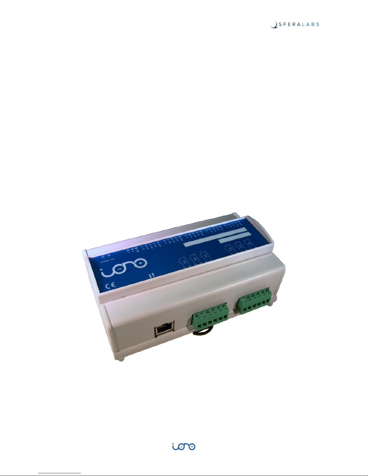
IAMU21X Iono Arduino Uno
IAME21X Iono Arduino Ethernet
IAMS21X Iono Arduino Solo
a general-purpose, professional input/output module based on a standard Arduino board
"

Safety information 4
Qualified personnel 4
Hazard levels 4
Safety instructions 5
General safety instructions 5
Introduction 6
Features 7
Usage and connections 8
Power supply 8
Multi-mode inputs: analog mode 9
Multi-mode inputs: digital mode 9
DI5 and DI6 digital inputs 9
Analog output 10
Relay digital outputs 10
RS-485 serial port 10
Mapping 11
Working with 5.0V and 3.3V boards 12
Quick start 13
Iono Arduino Ethernet 13
Iono Arduino Uno 13
Iono Arduino Solo 13
Iono Arduino Ethernet web app user guide 15
Factory reset 15
HTTP API 15
Modbus RTU Slave user guide 16
Console 16
Modbus address tables and functions 17
Relays 17
Analog (PWM) output 17
Digital inputs 17
Analog inputs and digital counters 18
Installing and removing the Arduino board 20
Iono Arduino Software Development 22
Programming 22
Arduino Uno 22
Arduino Ethernet 22
1
User Guide

Block diagram 24
Board layout 25
Technical specifications 26
Dimensions 28
Disposal 29
Installation and use restrictions 29
Standards and regulations 29
Safety instructions 29
Set-up 29
Conformity Information 30
EU 30
2
User Guide

Be sure to always remove the power supply before installing or
removing the Arduino board inside Iono Arduino.
Iono Arduino must be operated with both side covers installed.
Follow all applicable electrical safety standards, guidelines,
specifications and regulations for installation, wiring and operations of
Iono Arduino modules.
Carefully and fully read this Iono Arduino user guide before installation.
Iono Arduino is not authorised for use in safety-critical applications where a failure of the
product would reasonably be expected to cause personal injury or death. Safety-critical
applications include, without limitation, life support devices and systems, equipment or
systems for the operation of nuclear facilities and weapons systems. Iono Arduino is
neither designed nor intended for use in military or aerospace applications or
environments and for automotive applications or environment. Customer acknowledges
and agrees that any such use of Iono Arduino is solely at Customer's risk, and that
Customer is solely responsible for compliance with all legal and regulatory requirements in
connection with such use.
Sfera Labs S.r.l. may make changes to specifications and product descriptions at any time,
without notice. The product information on the web site or materials is subject to change
without notice.
Please download and read the Sfera Labs Terms and Conditions document available at:
http://www.sferalabs.cc
Iono and Sfera Labs are trademarks of Sfera Labs S.r.l. Other brands and names may be
claimed as the property of others.
#
Copyright © 2015-2017 Sfera Labs S.r.l. All rights reserved.
3
User Guide

Safety information
Carefully and fully read this user guide before installation and retain it for future reference.
Qualified personnel
The product described in this manual must be operated only by personnel qualified for the
specific task and installation environment, in accordance with all relevant documentation
and safety instructions. A qualified person should be capable of fully identifying all
installation and operation risks and avoid potential hazards when working with this product.
Hazard levels
This manual contains information you must observe to ensure your personal safety and
prevent damage to property. Safety information in this manual are highlighted by the safety
symbols below, graded according to the degree of danger.
Indicates a hazardous situation which, if not avoided, will result in death or serious
personal injury.
Indicates a hazardous situation which, if not avoided, may result in death or serious
personal injury.
Indicates a hazardous situation which, if not avoided, can result in minor or moderate
personal injury.
Indicates a situation which, if not avoided, can result in damage of property.
DANGER
WARNING
CAUTION
NOTICE
4
User Guide

Safety instructions
General safety instructions
Protect the unit against moisture, dirt and any kind of damage during transport, storage
and operation. Do not operate the unit outside the specified technical data.
Never open the housing. If not otherwise specified, install in closed housing (e.g.
distribution cabinet). Earth the unit at the terminals provided, if existing, for this purpose.
Do not obstruct cooling of the unit. Keep out of the reach of children.
Life threatening voltages are present within and around an open control cabinet.
When installing this product in a control cabinet or any other areas where dangerous
voltages are present, always switch off the power supply to the cabinet or equipment.
Risk of fire if not installed and operated properly.
Follow all applicable electrical safety standards, guidelines, specifications and regulations
for installation, wiring and operations of this product.
Ensure that the product is properly installed and ventilated to prevent overheat.
The connection of expansion devices to this product may damage the product and other
connected systems, and may violate safety rules and regulations regarding radio
interference and electromagnetic compatibility.
Use only appropriate tools when installing this product. Using excessive force with tools
may damage the product, alter its characteristics or degrade its safety.
WARNING
WARNING
NOTICE
5
User Guide
Introduction
Iono Arduino combines the ease of use of the Arduino platform with multiple input and
output interfaces; the result is a rugged, safe, reliable and easy to connect module, suited
for installation both in industrial and residential environments.
Iono Arduino is available in three versions, all using the same shield board and case, but
with different Arduino boards pre-installed.
Iono Arduino Ethernet has an Arduino Ethernet board, while Iono Arduino Uno uses an
Arduino Uno board.
Iono Arduino Solo comes without any Arduino board, so you can use your preferred
Arduino board, as far as it is fully compatible with the Arduino 1.0 pinout and fits the Iono
Arduino case.
The different versions all share the same I/O board and case, and the electrical
characteristics are common. The information contained in this manual cover all versions,
except where explicitly stated otherwise.
6
User Guide

Features
The Iono Arduino modules key features are:
✓
12÷24Vdc power supply
✓
compatible with 5.0V and 3.3V operating voltage Arduino boards
✓
4 multi-mode inputs: either to be used as digital or as 0÷10V or 0÷20mA analog signals
✓
2 digital inputs for potential-free contacts
✓
1 analog output 0÷10V controlled by PWM signal
✓
redundancy of common terminals for simplified wiring
✓
6 power relay outputs rated for 12A at 250V, which can tolerate large peak currents
(inrush current) up to 80A
✓
output relays with bistable coil, to minimize the current consumption
✓
standard RS-485 interfaces to the Arduino serial pins with automatic TX/RX switching,
and electrostatic discharge protection
✓
built-in slot for the installation of an Arduino Uno, Arduino Ethernet or Arduino Zero
board
✓
removable terminal blocks for easier installation
✓
inputs protected against electrostatic discharges and temporary over voltages
✓
double internal insulation between high voltage areas (relay outputs) and all other
components
✓
standard modular housing 9 units size, suitable for mounting on Omega rail.
7
User Guide

Usage and connections
FIGURE 1 CONNECTION EXAMPLE
Power supply
Iono Arduino can be powered with DC voltage only:
✓ DC: nominal voltage in the range 12V to 24V (MIN=11, MAX=30Vdc)
Respect the correct polarity shown in the schematic diagram (+ -). The power supply
circuit implements reverse polarity protection using an auto resetting fuse and surge
protection up to ±500V/2ohms 1.2/50μs.
8
User Guide

Multi-mode inputs: analog mode
Iono Arduino features 4 multi-mode inputs (1, 2, 3, 4). Depending on terminal blocks
wiring, digital (ON-OFF), analog 0÷10V or analog 0÷20mA signals can be applied.
When using analog inputs, 0÷10V and 0÷20mA are converted to 0÷3.3V levels in order to
be compatible with the Arduino platform input pins. Both active and passive 0÷20mA (or
4÷20mA) transmitters can be connected, using the C+ terminal as power supply; the
0÷20mA transmitter shown in the schematic here below is a 2-wire passive type.
Multi-mode inputs: digital mode
In digital mode, an external potential free contact can be connected between terminals C+
and DIx (x=1, 2, 3, 4); otherwise, the DIx terminal can be connected to an external voltage
signal (in the range 9÷40V) referred to the GND of the Iono Arduino module.
DI5 and DI6 digital inputs
An external potential free contact can be connected between terminals C+ and DIx (x=5,
6); otherwise, the DIx terminal can be connected to an external voltage signal (in the range
9÷40V) referred to the GND of the Iono Arduino module.
DI5 and DI6 are connected to the Arduino board through a protection network. If you need
to bypass the protection resistors you can move jumpers J1 and J2, respectively for DI5
and DI6, to the BYP position.
DI5-DI6 JUMPERS SCHEMATIC
Note that, with the jumpers in the BYP position, you should limit the maximum voltage
applied to DI5 or DI6 to the voltage levels accepted by the Arduino board installed in Iono
Arduino. Exceeding the Arduino voltage range will result in damage to the Arduino board
and Iono Arduino.
NOTICE
9
User Guide

J1-J2 JUMPERS POSITION
Analog output
Iono Arduino features a 0÷10V output (AO1) which can be controlled by the PWM function
of the Arduino platform; the 0÷100% duty cycle of PWM signal corresponds to a 0÷10V
output voltage.
This is a sink/source output (the current direction at this output can be both positive and
negative).
Relay digital outputs
Iono Arduino features 6 power relay outputs which can withstand high inrush currents
thanks to the special contact built.
These relays have bistable coils, which are powered only for the short time needed to
move the contact from one position to the other one.
This guarantees very low total current consumption and low power dissipation resulting in
lower self-heating. It also maintains ”mechanical memory” in case of module power supply
failure.
A dedicated internal circuit manages the relay coils, matching the closed status of each
relay to the high state of the related control pin of the Arduino platform.
RS-485 serial port
Iono Arduino uses the Arduino UART TX/RX pins to implement a standard RS-485 serial
port.
Simply connect the RS-485 A, B and GND to the RS-485 pins of the terminal block.
The RS-485 port is protected from ESD and voltage surges, and supports half-duplex
communication with automatic TX/RX switching from 1200 to 115200 bps.
10
User Guide

The RS-485 TX/RX switching is implemented automatically in the Iono’s micro-controller,
based on speed and number of bits detection, and is completely transparent to the
software controlling the UART on Arduino.
The RS-485 line has 620 Ohm pull-up and pull-down resistors on lines A and B. The
biasing resistors ensure that, during idle periods the data lines are kept at a stable voltage
level and prevent false triggering of receiver input. These resistors can be enabled
installing jumpers J4 and J5 respectively.
A 120 Ohm termination resistor between A and B can be enabled installing jumper J3.
RS-485 JUMPERS SCHEMATIC
RS-485 JUMPERS POSITION
Mapping
The following table shows the mapping of the inputs and outputs of the Iono Arduino
module into the related pins of the Arduino platform.
11
User Guide

Working with 5.0V and 3.3V boards
Iono Arduino is compatible with both 5.0V and 3.3V operating voltage Arduino boards.
All digital I/O and the PWM-based analog output A01 work transparently with both 5.0V
and 3.3V Arduino pins
The 0-10V and 0-20mA analog inputs are translated to a voltage range between 0 and
3.3V to the analog pins of the Arduino boards. If you are using a board with 5.0V operating
voltage, you will have to use the external voltage reference (AREF) for the Arduino analogto-digital converter. The Iono Arduino board connects the Arduino AREF pin to 3.3V. If you
are using an Arduino board in a way that is incompatible with the 3.3V voltage applied to
AREF, you can move the J6 jumper to the “OPEN” position in order to leave the AREF pin
unconnected.
AREF JUMPER POSITION
Iono Arduino inputs and outputs
Arduino pins
DI1 – AV1 – AI1
A0
DI2 – AV2 – AI2
A1
DI3 – AV3 – AI3
A2
DI4 – AV4 – AI4
A3
DI5
2
DI6
3
DO1
A4
DO2
A5
DO3
5
DO4
6
DO5
7
DO6
8
AO1
9
RS-485
RX (0) / TX (1)
12
User Guide

Quick start
Follow the instructions below to start using your version of Iono Arduino.
Iono Arduino Ethernet
Iono Ethernet ships with our web app sketch pre-installed and the following network
configuration:
✓
Address: 192.168.0.100
✓
Netmask: 255.255.255.0
✓
Gateway: 192.168.0.1
✓
DNS: 192.168.0.1
1. connect Iono Arduino to a regulated power source (check the data sheet for the power
requirements)
2. check that the LD1 power LED, next to the power supply terminals, is on
3. connect Iono Arduino to your network and, from a device with a compatible network
address, go to the following URL using any modern web browser: http://192.168.0.100.
Note that JavaScript must be enabled on the browser
4. click the settings icon and enter your preferred network parameters and password,
then press save
5. you should now be able to access Iono Arduino again using the newly assigned
address.
Iono Arduino Uno
Iono Arduino Uno ships with the Modbus RTU Slave sketch pre-installed. This sketch
implements a fully functional standard Modbus RTU slave to monitor and control all I/O
lines of the Iono Arduino Uno module, and is also compatible with Arduino Zero.
1. connect Iono Arduino to a regulated power source (check the data sheet for the power
requirements)
2. check that the LD1 power LED, next to the power supply terminals, is on
3. read the Modbus RTU Slave chapter below to configure and use Iono Arduino Uno as a
Modbus RTU device.
Iono Arduino Solo
Iono Arduino Solo doesn’t ship with a pre-installed sketch, for the simple reason that there
is no Arduino module installed!
Before installing your own Arduino board, you should check that it powers-up normally.
1. connect Iono Arduino to a regulated power source (check the data sheet for the power
requirements)
2. gently remove the side covers on both sides
3. check that the LD1 power LED, next to the power supply terminals, is on
13
User Guide

4. remove the power supply
5. install your Arduino board and replace the side covers
6. reconnect the power supply and check that LD1 goes back on
14
User Guide

Iono Arduino Ethernet web app user guide
The pre-installed Iono Arduino Ethernet web app can be used from any modern browser,
including browsers of all mobile devices, to easily control the output relays, the 0…10V
analog output and check the status of all inputs.
JavaScript must be enabled on the browser, or this app will not work.
Simply push the DOx switches to flip the relays, or enter a decimal number, e.g. 8.3, then
press [set] to set the analog output.
From the control page you can access the configuration page pressing the icon on the topright corner.
Using the configuration page you can change the network parameters, including the MAC
address (unless you know exactly what you are doing, always use the MAC address
printed on the Arduino Ethernet board).
You can also set a password to restrict access to the web app. Please note that this app
does not use the HTTPS encrypted protocol and all data, including the password, are sent
over the network unencrypted.
Factory reset
The web app sketch implements a simple factory reset procedure, to restore the original
network settings and remove the password.
Power off Iono, then short-circuit pins DI5 and DI6, set the internal jumpers (J1 and J2) in
bypass position, and power it back on.
Now go to http://192.168.0.100/, set the new configuration and save, wait for the process
to complete, remove the short-circuit and replace the jumpers back in their original
position.
HTTP API
The web app includes an HTTP API for remote control from networked applications.
Visit this page for the details: https://github.com/sfera-labs/iono/wiki/IonoWeb#http-api
15
User Guide

Modbus RTU Slave user guide
In order to use Iono Arduino Uno as a Modbus RTU device, you first need to configure the
RS-485 communication parameters and Modbus address. A simple serial configuration
console is implemented in the sketch.
Console
The configuration console is accessed through the same serial port used for the Modbus
communication.
Set the serial port speed to 9600, 8 bits, no parity, no flow-control and connect to the
Arduino’s serial port using the Arduino USB port and your preferred serial terminal
program. You can also connect via the RS-485 terminal block on the Iono Arduino Uno
Module.
When the Arduino Uno is powered-up or reset, you can enter console mode by typing five
or more consecutive space characters within 15 seconds from reset. If any other character
is received, Arduino will enter the normal Modbus RTU mode.
Press 0 to show the current configuration, 1 to 3 to enter the serial port speed, serial port
parity, and the Modbus address.
Sfera Labs Iono Uno (2.0) - Modbus RTU slave configuration menu
0. Print current configuration
1. Speed (baud)
2. Parity
3. Modbus device address
4. Input/Output rules
5. Save configuration and restart
Type a menu number (0, 1, 2, 3, 4, 5): 0
Current configuration:
Speed (baud): 115200
Parity: Even
Modbus device address: 2
Input/Output rules: - - - - - -
Press 4 to define the Input/Output rules. With these rules you can configure each one of
the 6 digital inputs to control the corresponding output relay.
The rules string consists of six characters, where the leftmost character represents the rule
for DI1/DO1 and the rightmost character for DI6/DO6. The possible rules are:
•
F: follow - the relay is closed when input is high
•
I: invert - the relay is closed when input is low
•
H: flip on L>H transition - the relay is flipped at any input transition from low to high
•
L: flip on H>L transition - the relay is flipped at any input transition from high to low
•
T: flip on any transition - the relay is flipped at any input transition, both high to low and
low to high
16
User Guide

•
-: no rule - no control rule set for this relay.
Press 5 to review the configuration and confirm to save it. When the new configuration is
saved, Arduino will automatically reset and restart with the new configuration.
The configuration is permanently stored in the Arduino’s EEPROM memory, and retained
across restarts and power cycles.
Modbus address tables and functions
Relays
Use Modbus function Read Coils, at coil address 1 to 6, to read the status of the last
command given to the output relays. Because the relays are latching, the status will return
zero at boot, regardless of the actual position of the relays’ contacts.
Use functions Write Single Coil or Write Multiple Coils to control the relays output.
Analog (PWM) output
Use Modbus function Read Holding Registers at address 601 to read the status of the
analog output AO1. The returned value is in mV, so the value range is 0 to 10000.
Use function Write Single Register to control the voltage output of AO1.
Digital inputs
Digital inputs DI1 to DI6 can be read at two different address ranges, using function Read
Discrete Inputs.
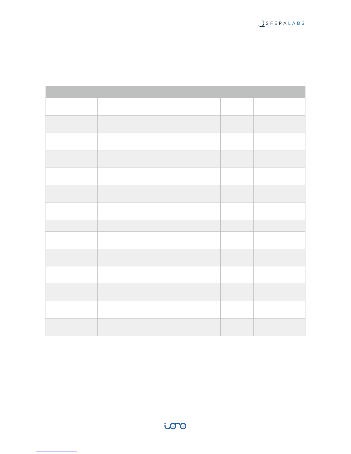
Address (decimal)
Size (bit)
Description
R/W
Functions
1
6
command of output relays
r/w
1, 5, 15
1
1
command relay 1
r/w
1, 5, 15
2
1
command relay 2
r/w
1, 5, 15
3
1
command relay 3
r/w
1, 5, 15
4
1
command relay 4
r/w
1, 5, 15
5
1
command relay 5
r/w
1, 5, 15
6
1
command relay 6
r/w
1, 5, 15
Address
(decimal)
Size
(word)
Description
R/W
Functions
Type
Range
Unit
601
1
write analog voltage
output AO1
r/w
3, 6
unsigned
short
0 - 10000
V/1000
17
User Guide
Reading addresses 101 to 106 returns the value of the input pins filtered with a de-bounce
function. This filter has a 50 ms time constant, so that a value change is reported only after
being stable for at least 50 milliseconds.
Reading addresses 111 to 116 returns the instantaneous value of the input pins, with no
de-bounce filter applied.
Analog inputs and digital counters
Use Modbus function Read Input Registers to read the values of analog inputs. Reading
addresses 201 to 204 returns the voltage on AV1 to AV4 in mV, from 0 to 10000. Reading
addresses 301 to 304 returns the current on AI1 to AI4 in mA/1000 (microAmperes), from 0
to 20000.
This sketch also implements counters on digital inputs. Reading input registers at address
1001 to 1006 returns unsigned short values from 0 to 65535. These counters are
Address (decimal)
Size (bit)
Description
R/W
Functions
101
6
read digital inputs (with debounce)
r
2
101
1
read digital input DI1 (with debounce)
r
2
102
1
read digital input DI2 (with debounce)
r
2
103
1
read digital input DI3 (with debounce)
r
2
104
1
read digital input DI4 (with debounce)
r
2
105
1
read digital input DI5 (with debounce)
r
2
106
1
read digital input DI6 (with debounce)
r
2
111
6
read digital inputs (no de-bounce)
r
2
111
1
read digital input DI1 (no debounce)
r
2
112
1
read digital input DI2 (no debounce)
r
2
113
1
read digital input DI3 (no debounce)
r
2
114
1
read digital input DI4 (no debounce)
r
2
115
1
read digital input DI5 (no debounce)
r
2
116
1
read digital input DI6 (no debounce)
r
2
18
User Guide

incremented by one (and rolled back to 0 after reaching 65535) on the positive rise of their
respective inputs, after the de-bounce filter.
Address
(decimal)
Size
(word)
Description
R/W
Functions
Type
Range
Unit
201
4
read analog voltage
inputs
r
4
201
1
read analog voltage
input AV1
r4unsigned
short
0 - 10000
V/1000
202
1
read analog voltage
input AV2
r4unsigned
short
0 - 10000
V/1000
203
1
read analog voltage
input AV3
r4unsigned
short
0 - 10000
V/1000
204
1
read analog voltage
input AV4
r4unsigned
short
0 - 10000
V/1000
301
4
read analog current
inputs
r
4
301
1
read analog current
input AI1
r4unsigned
short
0 - 20000
mA/1000
302
1
read analog current
input AI2
r4unsigned
short
0 - 20000
mA/1000
303
1
read analog current
input AI3
r4unsigned
short
0 - 20000
mA/1000
304
1
read analog current
input AI4
r4unsigned
short
0 - 20000
mA/1000
1001
6
read digital inputs
counters
r
4
1001
1
read digital input
DI1 counter
r4unsigned
short
0 - 65535
n/a
1002
1
read digital input
DI2 counter
r4unsigned
short
0 - 65535
n/a
1003
1
read digital input
DI3 counter
r4unsigned
short
0 - 65535
n/a
1004
1
read digital input
DI4 counter
r4unsigned
short
0 - 65535
n/a
1005
1
read digital input
DI5 counter
r4unsigned
short
0 - 65535
n/a
1006
1
read digital input
DI6 counter
r4unsigned
short
0 - 65535
n/a
19
User Guide

Installing and removing the Arduino board
With Iono Arduino Solo you will have to install your own Arduino compatible board. Iono
Arduino accepts the original Arduino Uno and Ethernet Rev 3 boards, or other boards that
are fully compatible with the Arduino 1.0 pinout specification, with 5.0V or 3.3V operating
voltages.
Installing boards that are not fully compatible, both mechanically and electrically, may and
probably will damage the Iono Arduino board, and may create a safety risk.
You are responsible for the installation of the Arduino board inside Iono Arduino
Solo. The factory warranty does not cover any damage directly or indirectly caused
by the installation and removal of Arduino or compatible boards in Iono.
Iono Arduino Solo is shipped with two plastic turrets next to the Arduino pins. These turrets
should fit in the corresponding holes on your board. You may want to remove the turrets if
they don’t fit your board. It is up to you to determine if the mechanical coupling between
Iono Arduino and the Arduino board is appropriate for your application.
FIGURE 2 TURRETS INSTALLED ON THE IONO ARDUINO BOARD
To install the Arduino board, first line-up the connectors pins on both sides and also the
Arduino board holes with the turrets heads. Visually confirm the alignment, then gently
push down on both sides at the same time to lock the board firmly in place.
FIGURE 3 AN ARDUINO BOARD WITH PINS AND TURRETS PROPERLY ALIGNED
To remove the board, you should apply a gentle pressure to separate the turrets heads
from the board. Be very careful to keep the Arduino board parallel to the Iono Arduino
20
User Guide

board at all times, or you will bend the connection pins. You may consider cutting the
turrets to simplify the removal of your Arduino board.
21
User Guide

Iono Arduino Software Development
Since Iono Arduino is just a super-sized I/O shield for a standard Arduino, you don’t need
any specific library to work on it.
Our libraries and examples, available with source code on GitHub, will provide you with
some handy utilities to speed up your development, including functionalities to monitor the
inputs (filtering out possible noise) and control the outputs, HTTP APIs, Modbus support
and much more.
Go to https://github.com/sfera-labs/iono/wiki to access the code and documentation.
Programming
Arduino Uno
The Arduino Uno board, when mounted into a Iono Arduino module, must be programmed
through the USB port.
Arduino Ethernet
The Arduino Ethernet board requires the “USB Serial Light Adapter” for programming, as
shown below.
FIGURE 4 THE USB SERIAL ADAPTER
In order to access the programming connector inside the Iono Arduino module, the cover
placed on the same side of the power supply terminal block must be removed, gently
sliding it outward, and giving access to the programming connector indicated by the red
arrow. The yellow arrow indicates the reset button of the Arduino board.
22
User Guide

FIGURE 5 USB ADAPTER CONNECTOR AND RESET BUTTON
Insert the USB Serial Adapter as shown below, with the components side facing down.
FIGURE 6 SERIAL ADAPTER CONNECTED TO THE ARDUINO BOARD
Connect the adapter to a PC and perform the programming as usual. This operation does
not require the Iono Arduino module to be connected to a power supply.
23
User Guide

Block diagram
FIGURE 7 BLOCK DIAGRAM
24
User Guide

Board layout
FIGURE 8 BOARD LAYOUT
25
User Guide
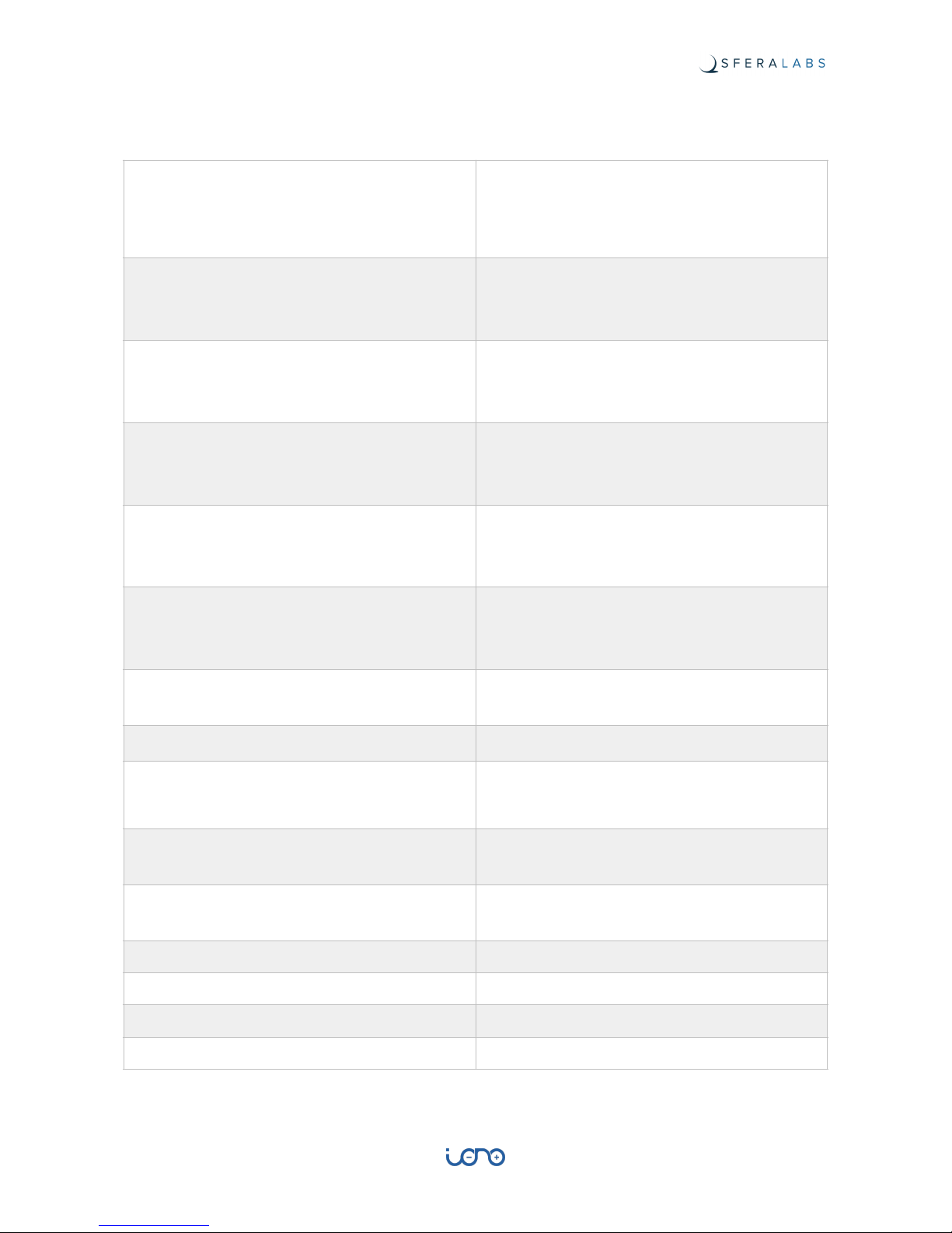
Technical specifications
Power supply
12…24V⎓ nom. (11…30V⎓ )
Reverse polarity and surge protection up to ±500V/
2ohms 1.2/50μs using an auto resetting fuse and
diodes
Current consumption at VS+ 12V⎓ and
unconnected inputs
13mA w/o Arduino
35mA with Arduino Uno
95mA with Arduino Ethernet
Current consumption at VS+ 12V⎓ and digital
inputs closed to C+
30mA w/o Arduino
55mA with Arduino Uno
115mA with Arduino Ethernet
Current consumption at VS+ 24V⎓ and
unconnected inputs
11mA w/o Arduino
22mA with Arduino Uno
52mA with Arduino Ethernet
Current consumption at VS+ 24V⎓ and digital
inputs closed to C+
45mA w/o Arduino
56mA with Arduino Uno
86mA with Arduino Ethernet
Arduino platform compatibility
Uno
Ethernet
Zero
Inputs
4 multi-mode (digital or analog 0…10V or 4…20mA)
2 digital
Voltage range at digital inputs (1-6)
9…40V⎓
Current for each digital input (1-6)
2,7mA at VS+ 12V⎓
5,5mA at VS+ 24V⎓
Voltage threshold digital inputs 1-4 (typ.)
VIH: 7.3V
VIL: 6.5V
Voltage threshold digital inputs 5-6 (typ.)
VIH: 4.8V
VIL: 4.7V
Impedance for analog 0…10V inputs (1¸4)
143kΩ
Impedance for analog 0…20mA inputs (1-4)
165Ω
Conversion error for analog 0…10V inputs (1-4)
2% of full scale
Conversion error for analog 0…20mA inputs (1-4)
2% of full scale
26
User Guide

Max cable length for digital inputs (1-6)
30 meters
Max cable length for analog inputs (1-4)
15 meters
Digital outputs
6 power relays with bistable coil
MAX output contact rating (each output)
Resistive load (cos φ = 1): 12A at 250V~ (3000VA)
Inductive load (cos φ = 0.5): 3.6A at 250V~ (900VA)
Incandescent lamps: 8A at 250V~ (2000VA)
Fluorescent lamps: 350W with 42uF MAX power
factor correction capacitor
Resistive load (DC): 12A at 24Vdc / 1A at 60Vdc
Analog output
0…10V PWM controlled by Arduino PWM out
max 10 mA source/sink current
Suggested minimum PWM frequency for analog
output
120 Hz
Duty cycle to voltage error for analog output
2% of full scale
Communication ports
USB for Arduino Uno
Ethernet for Arduino Ethernet
RS-485 half-duplex with automatic data direction
management
Baud Rates on COMM ports
1200 to 115200
ESD-Protection Voltage on RS-485 A/B
±15kV human body model
±8kV contact discharge
Surge protection on RS-485 A/B
Surge protection up to ±500V/2ohms 1.2/50μs;
600W peak pulse power capability at 10/1000μs
waveform
Fail safe feature on RS-485
Yes
Housing
standard 9M for DIN rail
Operating temperature
0…+50 °C
Storage temperature
-20…+70 °C
Protection degree
IP20
Weight
275 g (Iono Arduino Solo)
295 g (Iono Arduino Uno)
300 g (Iono Arduino Ethernet)
27
User Guide

Dimensions
FIGURE 9 DIMENSIONS
28
User Guide

Disposal
(Waste Electrical & Electronic Equipment)
(Applicable in the European Union and other European countries with separate
collection systems). This marking on the product, accessories or literature
indicates that the product should not be disposed of with other household
waste at the end of their working life. To prevent possible harm to the
environment or human health from uncontrolled waste disposal, please
separate these items from other types of waste and recycle them responsibly
to promote the sustainable reuse of material resources. Household users
should contact either the retailer where they purchased this product, or their local
government office, for details of where and how they can take these items for
environmentally safe recycling. This product and its electronic accessories should not be
mixed with other commercial wastes for disposal.
Installation and use restrictions
Standards and regulations
The design and the setting up of electrical systems must be performed according to the
relevant standards, guidelines, specifications and regulations of the relevant country. The
installation, configuration and programming of the devices must be carried out by trained
personnel.
The installation and wiring of connected devices must be performed according to the
recommendations of the manufacturers (reported on the specific data sheet of the product)
and according to the applicable standards.
All the relevant safety regulations, e.g. accident prevention regulations, law on technical
work equipment, must also be observed.
Safety instructions
Carefully read the safety information section at the beginning of this document.
Set-up
For the first installation of the device proceed according to the following procedure:
✓
make sure all power supplies are disconnected
✓
install and wire the device according to the schematic diagrams on the specific data
sheet of the product
✓
after completing the previous steps, switch on the 230 Vac supplying the power supply
and the other related circuits.
29
User Guide

Conformity Information
EU
This device complies with the essential requirements of the following directives and
harmonised standards:
✓
2014/35/UE (Low Voltage)
✓
2014/30/UE (EMC)
✓
EN61000-6-2:2005 (EMC Immunity)
✓
EN60664-1:2007 (Electrical safety)
✓
EN61000-6-3:2007 (Emission for residential, commercial and light-industrial
environments)
✓
2011/65/UE (RoHS)
The declaration of conformity is available on the internet at the following address: https://
www.sferalabs.cc/iono-arduino/
30
User Guide
 Loading...