


Lmg
the
wh
Q&?s
Lktacficn
PLEASE READTHESE INSTRUCTIONS
BEFORE INSTALLING THE GAS ALARM
&
Zl
Oe
Operating
&
Installation Manual
Mains
and
DC
powered
~ohestic
Gas
Alarms
Models
for
Natural
Gas
and
LP
Gas
I
zellweger
anatytics
A
Division
of
the
Zellweger
Lwva
Group
SAFETY
The Alarm should
only
be
installed
by
a
cornpeten1
person
using the following inrlallation inrlruclionr
TZ.~',.
3.1
i?,ira
I;l:i, if
a,jr!l
,~ua~lahlr
in
Ilh
ssrw\
Illcis
arc
ds
'o:lc,:-.
ii:i
:ii'~.r.il
Gab.
~sal,!s
I:-AP~CI
fl 10-ZJOVdi
i'J
GOHI)
ZlGd
?ru;;ar:?
iro
01;'dre
ILK],
maips
c:.;c:ad
(Illl~i3DVa-
3
C'IHi]
,?I1
:
Pr0lnl.r
and
Ua!are I ?GI.
DC
PO:.?^?:!
8
li
7l\~t!~)
fS~>!,.~,~l\l
LPG
alarm,
!r:r
baa',
~rr
as3
d\dtldliI!)
ir,$~jri
y381
lbivi I).,. cs.n.1 n~~:'I?l
'or
y,:ur
,II~':L'IL,~I lbjrl~p:;~nq 1I.p uc?
(1.1
lh? pmi~;;l
I\i;!ilr I).?
I.I:I~
rly 511~plj,lh?l:11~ $'a111117 1111. ~r?sla'lai
,dn
All t~li,lrrai
:.,ring
sI.o~!rl
t?
nilai!eo
arco!d
(13
lo
icu
0:aI
*l~:lllC~i
idf~I;
II,JL61l11:11
Dl:.
,I,,
~n!
Ihai
I;rn
11i1al.r~ 113 r101 IsrnllCr
;.till
lhi
i~irl~iil
lbia JIairn
-
jc.1
~I~J~SIOP
lll~
alarm :.s,ing.
tr.
re;'\,
211
tl~;:i:
i'
l::i
::0
llldlnlenal
IL.
11.
ioliiil~lll,! ra;li.lra%l
WHERE NOT TO INSTALL THE ALARM
WHERE TO INSTALL THE ALARM
!ii-
nlax!n.unl
prwlr:l
3r
1111, ;1I,irnl ihl,,.I
?e
~ila\li~.I
ii~
i
Iai i,.i
11
'l.?
rcall
;.?e;c
:hc ,lir aullla~l:
a
IS
ilila:id
11,
"t,,!
~nsl~ll~~~~~~~~
'h,s
>,#I1
52
I$IP
~,;,d.cr
4"
11~ :#It1
cl
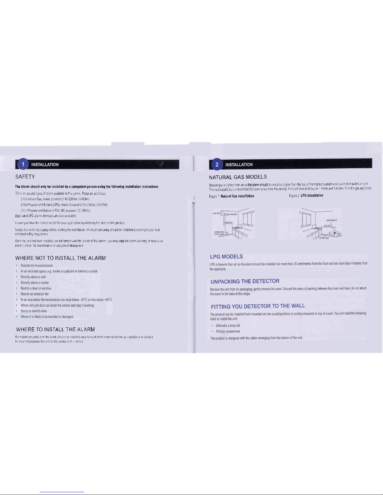
NATURAL GAS MODELS
:~~l~,~i
gii
,s
I
QI.~~,
1h3n
a;,
10
?arm si.odirl
kc
r~lips
I:!",
1ttj.1
hi
:op
91 'le h*qhiri riijlsdr
uric..;
or
dr.ra,:P
7
7
r.2-
~l,,~:;,(
L;
I
7
mere
3'3
rrol,.,
;,rib
17on1 ~l-e
ccinc I c,.~.;lld a150
b?
bab:,i..:~
'
rrclrc
md
L>
n.~lrr;
'r,
21
ll? ylsani.1
?l:e
Flqi!~ ' Natural
Gar
lnrlailalion
Flg~ie
2
LPG
Installalion

Flush
mounting
Surfaos
Mounting
HOW
TO CONNECT
POWER TO
THE
ALARM
~daramwdmgpwaplwaryoll~~~~~kc~~r~ocl-,~'~~~
mwpodud
Fpm5
hm

INSTALLATION
Mains
Powered
Alarms
CAUTION: ISOUTE THE MAINS BEFORE ST1RnNG WORK
Thedecwwshauhi bemredlo Ihe maim
wpphl*
w wnwildrd
hsed
Wet
lo
BS5733
The luse shwld be raled a1
3,471~
bnrm~redwimshauldbemnecledloIhelivelmi~I~aL$larandIheM~wM~~m~houldbe~~ecledlolhe
mi
tminal
shm
a
N.
lh!
eat
lmiml is n quired.
Fqua
7
AC
Supply
Wrlng
DC
Powered
Alarms
CAUTION: ISOLATE THE MAINS BEFORE STARTING
WORK
~detBCI~shwldt8wiRdloIhe
1Zv~24Vwpplymlhaluy~eda(3AmprPrTheredwim~ld
kunnecledtolheterminal
simm
belawmlh a + (plus) sqn
and
Ihe
Mmre
lo lenniml
B
an. hing hemnmions
may
dwnsgehwm.
In
cams
aM mw-mmer Inf EiecIa
hd
be mmed lo
Ine
D*lnry
wpplyna(ne
matn
smlch Thlrmll
mwre
opralm
&en
la
umn
s
%pea
Rmaoem
conmon
la
pow
Ws
may
uure
a fill
bglRy
11
he
baaeyrematm
urhaw
Figure
8
DC
Supply Wlrlng
HOW
TO USE THE
INTERCONNECT
FACILITY
lh!inlenm~~ilityanbeuEedlolinkuploMalmlhealamll
If
oneunildmuhidececlgat.To
linkdamin
dgnapehrnmducl
Figurn 9 Palsy
Wring
AImA Alann
0
AI-C.
D
nc
HOW
TO
USE
THE RELAY
FACILITY
The
w!ay
pmvides
a
rn
d
sigmlling~
alanr
W~M
lo
I
m
w
as
mUol pawl wrmM
llCanalsobeusedloshddIa~~IveinlheevenIda~MlslCTherelayisaslngkpole~~lha(al
lobeeilheraoenwclosedrhenmirdec~.YwunlkbanwewiRdinonll~lo~walmsiaoaIHhBn
,
.
unneded deiw
gat.
For
the
mains
parand
wnlonsthr
nlay
conlad
Is
spwlikd
up
to
uW
@
Mac
and
lor
DC
pawnd
wnlons
llr
lr
rpeclfled
at
UV
B
BI
Flgum 10 Relay Wlrlnp
m*
Com
NC
NO

COMPLETING THE INSTALLATION
On he I k
wid lh
k
a ti he I and W een e Id
and
bas. Em
Ihe
lug is
1
Iirm~ In place and IheMring isrpcsredlu lhe lid.
The
wcan !hen
be
pushed mlo le
base
and
wud using
he
lwrclig wlded
inlo lhe cover.
When
the power is applied all lhree LEDs skuld
cmon
Iw5semods. During lhis pricd Le bumshould
mak5shMI
chirps.
Thisveiliff lhal
Ihe
alarm is wwXing correcUy. lhe
unilnilwill
then enlm its warm up madevAl~eh may take upto 20m1num. &his
pecicd Ihe Green pwr LEDvnll flash with
Ik
olki
LED5 not lil. During his pDocd Ihe de(ecb is capable of M~lingw high
wncenlrations ol gas bulmll
nil
opwate lullywilhin s~irICdtim. Mw IhispM Ihe Green LED Mll lum
on
continuwslylo icdim
wmal oprallm.
REMOVING THE COVER
I
More
rernmrq
me
rmr.
ms.m me
ma
ns
w
OC
uppb ha
tean
smlm of1
ana
lhal me green
pwr
LED
IS
no(
1.1
P~sh
M
ma1
sc~mdrrven
nlo
tne
~a
no
er
on one m 01 loe
m
L
Then
genly pns Vlal en0 d lhs
mer
dl
I$peal
m
s
process
!a
lhe 0th~ end
I
and lilt Ihe vAlolecworoll
Ik
base.
Da
carelul not to
damage
Ihemring behveen lhe mand base.
,
,':,
-
1
. .
-,
-
A
Division of
the Zellweger
Luwa
Group:
OPERATION
The alarm has Ihree
LED
lighlsmd
ane
Mtonm
Ihelmnl panel.
Fig 1 Conhl
Unit
Grem
Power
-
Indimes Ihe alam is
mhiqsullim~
p
wer
I$d
Alarm
-
Gas &.%led
Ydlav
Faull- The alarm
ha
an
in(ema1 laul

-
.
ACClDENTALLY
SETTING
OFF
THE
ALARM
ThitrlerlaMlh@wdIc*Matan.~
mdrnrb-bndLRIR~m
*k*drPlluHlm..
If-&
p
should
take
th.
WHEN
TO
PRESS THE TESTIHUSH
BUTTON
The
bunon
on
lhe
ltml
ol
healan
has
wrsl
dlllerenl
fundim
dewding up
h
level
olg
wnt
The
bunwmll
s~wd
and
Ihe
alannLECJmll
fli(ah

FAULT
CONDITIONS AND SIGNALS
,
MAINS POWERED ALARMS
In~mf~~
lfBlaEWtcvsatl
3kwhw&c!~dW~
~~
kllan4wa5
/
--
DC POWERED
ALARMS
'
lm
*b'
WC
Blo27Mbdc
Jkw
!e$slhn4m
ALL
ALARMS
-l
i
-
Garrlaected
Wdkbuhml)
L%RroeasW)uW*)
~d*rhulahl
R~I#B d blgh
kl
ah
-wolDIO*I*

i
,
OPERATION
GUARANTEE
C&Munitsshould
be
reUned
lo:
SF
Dr(W.4
SlinW
Road.
NW
IndWial
We.
M,
LbM
BH17OIU.
mis
~WBB
does
m(
alledywr
Mldary
@Is.
'..
The q nnection to the relay on your
ZIO
should be as follows
~igud
10
Relay Wiring
I
NO COM NC
urther Notes on Connection of Gas
Shut
Off
Valves
'
NonnaRyOpa,
--
I
j
I
IfWg~lslunsdoRvrh.nWpowwla~lo
Ifthegaslatumedoffwhsnthe~tolJmw&e
,
ho
valve
lhsn
use
Ma
~~~tlgurn~,
la
removed
Ulen
use
Ulfs
con-bn.
The
vab
1
wAldosewhengeslaW~cfHha,UWI~
I
'
Is
mlemrpled.
I
)
I
I
I
,
:
F
tl
I
I
.
*
 Loading...