

224
1
03.11
IND3
The user should retain these instructions for future reference • A lire attentivement et à conserver à titre d’information
226692
This product must be installed in strict accordance with local plumbing codes.
Le produit doit être installé dans le respect des règlements sanitaires locaux.
INSTALLATION AND MAINTENANCE INSTRUCTIONS
INSTRUCTIONS D’INSTALLATION ET D’ENTRETIEN
Product should be installed by a licensed plumber.
Le produit doit être installé par un plombier qualifié.
CDN
USA
1
2
A
D
G
x 1
x 2
x 2
H
E
B
x 1
3
1
/4”
9-
1-1/4”
/2”
1
1-
1-3/4”
K
x 2
x 1
x 2
/4”
1
12-
9”
x 2
C
x 2
I
x 2
F
x 2
J
10-1/4”
4
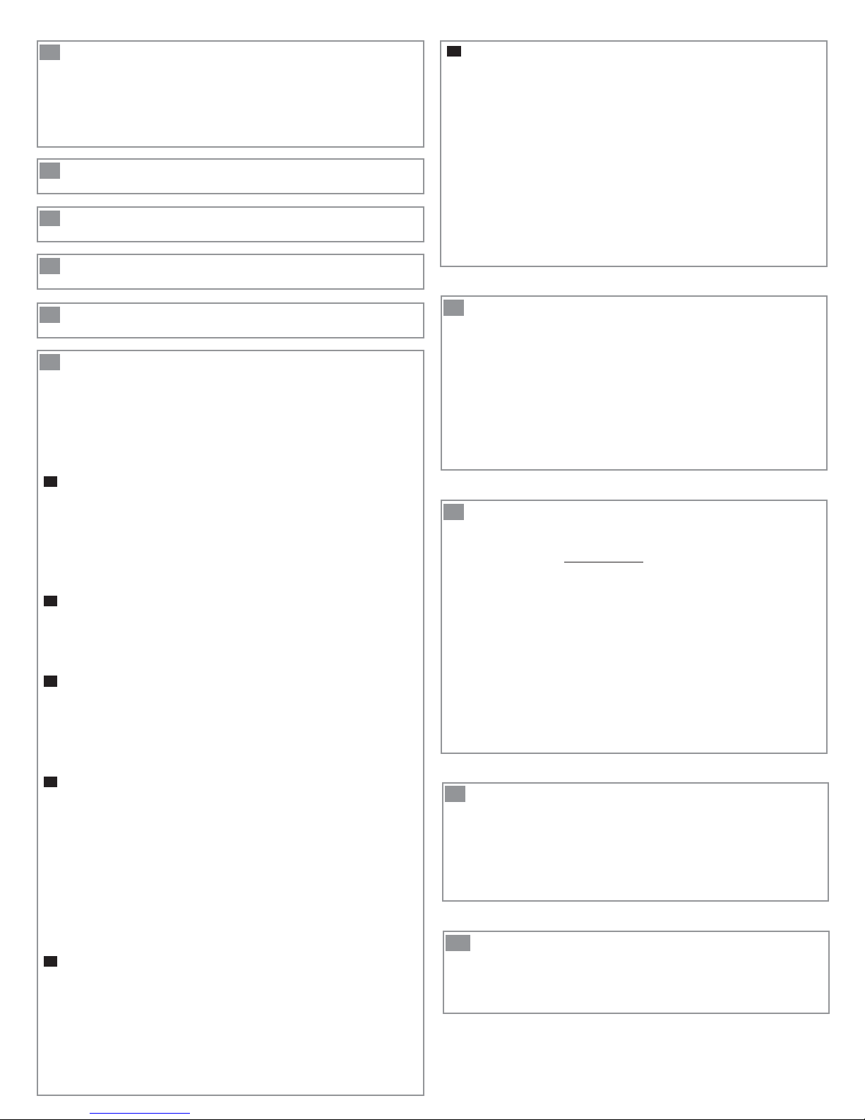
14
9
6
3
VERTICAL DISTANCE (ft)
DISTANCE VERTICALE (ft)
0
0 5 10 15 20 25 30 35 40
Flow Rate (US gallon/mn) • Débit (US gallon/mn)
5

6
6a
B A
J
I
6b 6c
> 8 po
E D C
K
6d 6e
G
F
H
G
1
DESCRIPTION
The SANISWIFT
®
is a gray water pump that is ideally
suitable for use in any section of the house where
additional fixtures are needed. It will pump the waste water
away from a variety of sources such as: laundry sink, washing
machine (indirect connection), dishwasher, bar sink, etc.
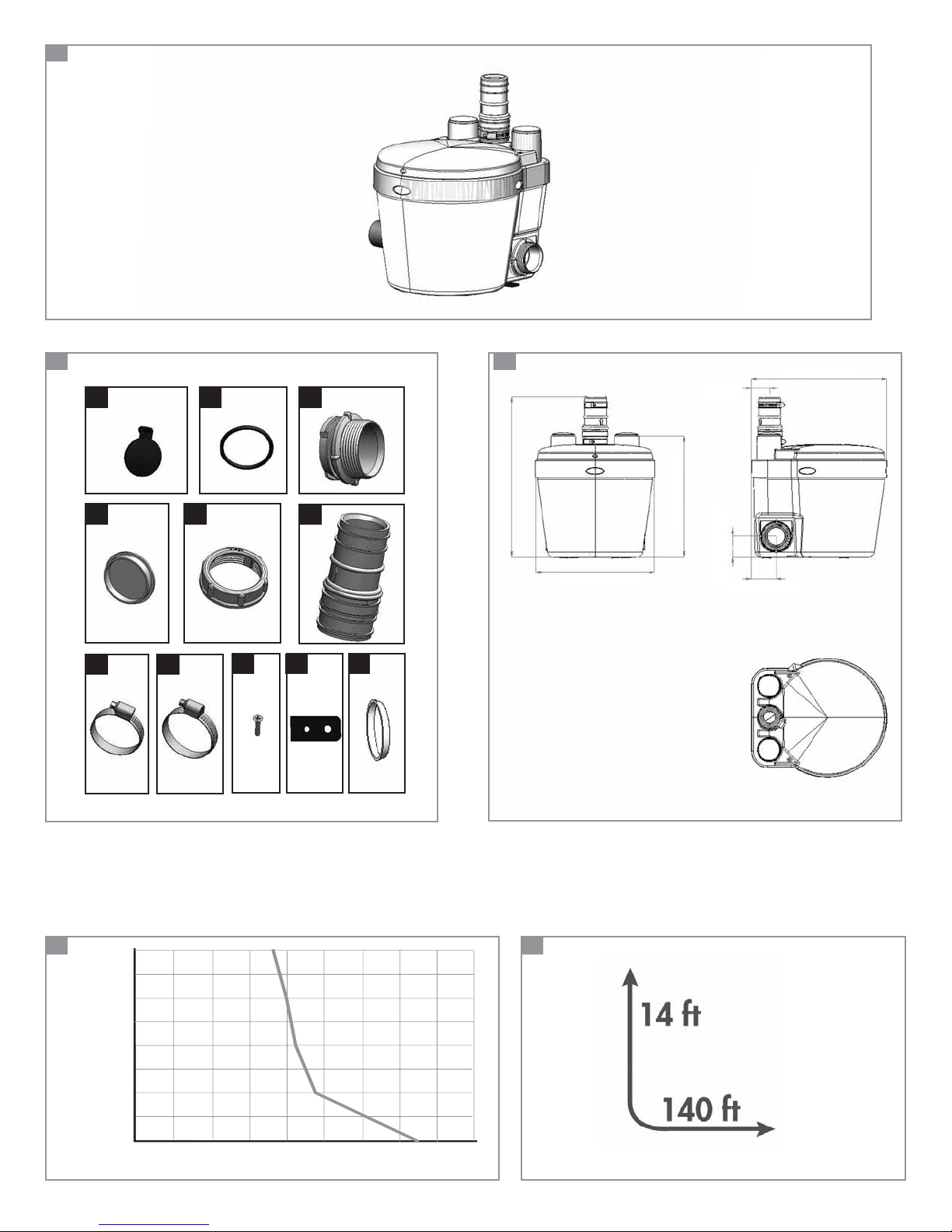
2
SPARE PARTS
See fig. n°2 page 2.
3
DIMENSIONS
See fig. n°3 page 2.
4
PERFORMANCE CURVE
See fig. n°4 page 2.
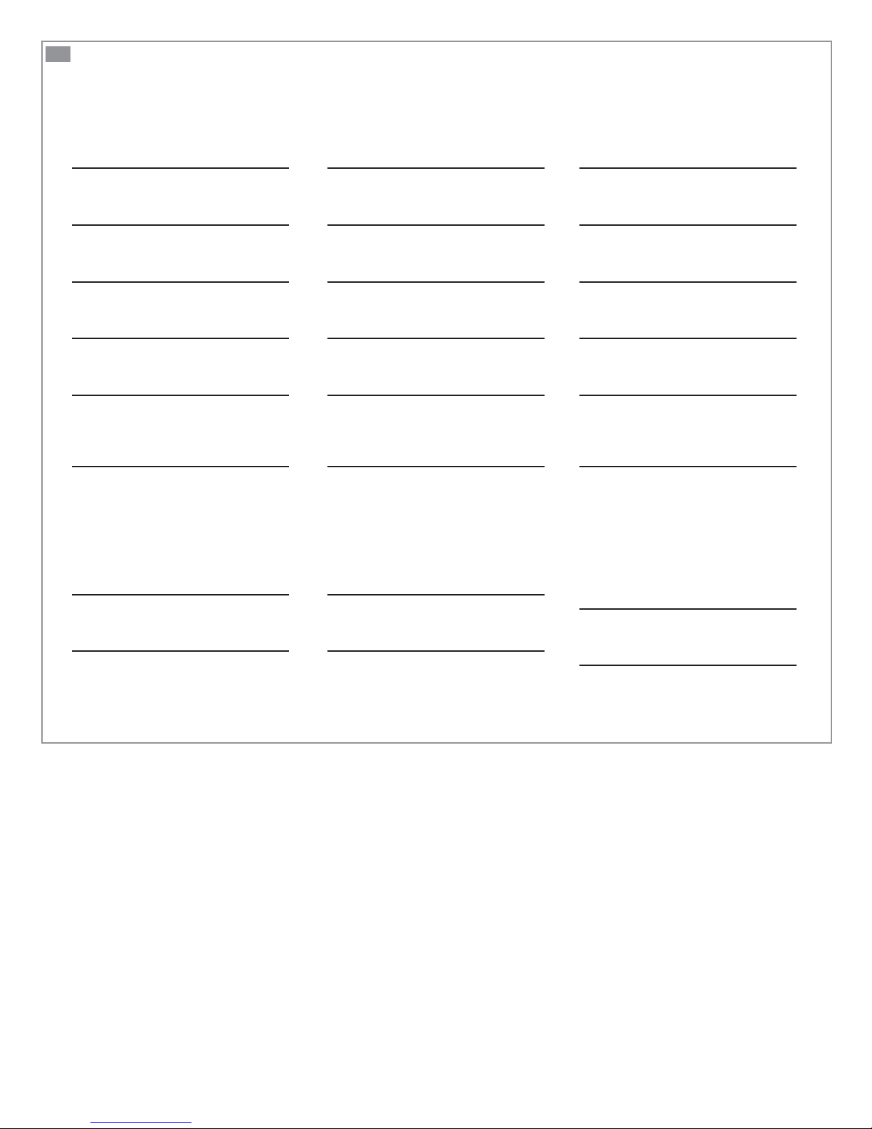
5
DISCHARGE HEIGHT
See fig. n°5 page 2.
6
INSTALLATION
This appliance must be installed following our instruction
manual and installation guidelines. It must also be installed
in such a way as to ensure easy access for repair and maintenance and in accordance with local plumbing code : CSA B45.9;
ASME A112.3.4.
6f
CONNECTION TO THE POWER SUPPLY
CONNECT ONLY TO RECEPTACLE PROTECTED BY A
GROUND FAULT CIRCUIT
WARNING: RISK OF ELECTRIC SHOCK - THIS PUMP
IS SUPPLIED WITH GROUNDING CONDUCTOR AND
GROUNDING TYPE ATTACHMENT PLUG. TO REDUCE
THE RISK OF ELECTRICAL SHOCK BE CERTAIN THAT
IT IS CONNECTED ONLY TO A PROPERLY GROUNDEDTYPE RECEPTACLE
All electrical connections must comply with local codes in
your region. The current must be single-phase 110-115 V,
15A. The electrical outlet must be located at the minimum
distance of 40 inches from the shower or bath. Note to only
connect this appliance to a ground fault circuit interrupter
(GFCI).
7
STANDARDS
This model is eligible to bear the CSA mark shown with
adjacent indicators “C” and “US”. The “C” and “US” indicators
adjacent to the CSA mark signify that the product has been
tested according to the applicable CSA (CAN) and ANSI/UL
standards for use in Canada and the USA. This includes
products eligible bear the designation NTRL. NTRL (Nationally
Recognized Testing Laboratory) is a designation awarded by
the American Occupational Safety and Health Administration
(OSHA) to laboratories authorized to award the certification
according to American standards.
6a
CONNECTION TO SIDE INLETS
The pump is equipped with a couple of side inlets that are
used to connect additional fixtures. To connect the side inlets,
use 11/2” PVC schedule 40 female adapters.
If either side inlet is not being used, ensure that you cap off
the inlet not being used by screwing the end cap into the case
until it is completely sealed.
6b
CONNECTION TO INLETS (TOP)
Carefully, using a cutter device, cut open the inlet that will be
used for this connection. Please note that the hole being cut
must be perfectly smooth in order to create a watertight seal.
6c
CONNECTION TO A BATHTUB / SHOWER.
When adding a bathtub/shower, a base will have to be
constructed. This base should be made out of a 2” x 6”
(minimum) or 2”x 8” (recommended) on edge, to allow for the
installation of a P-trap and the required 1/4” per foot gravity
flow towards the pump unit.
6d
DISCHARGE CONNECTION
The waste water being evacuated by this device must be
discharged using a 1 inch diameter copper or plastic (PVC,
CPVC) pipe. This pump is designed to handle
3
/8” particles.
The discharge pipe must be connected to a drain line or sewer
line using an approved “Y” fitting designed for this purpose.
Ensure that the angle of slope is 1/4“ per foot for horizontal
drain sections leading up to the main drain stack to ensure
drainage by gravity.
Install an optional ball valve at the bottom of the drain pipe
riser to allow shut off in case of repairs.
6e
CONNECTION TO A VENTILATION SYSTEM
This unit has been designed with a vent connection on the top
of the pump. All plumbing codes require connection to a vent
system. Connect your vent system using a 1-
1
/2” PVC or ABS
pipe.
Please note that the vent system should be a two-way air
vent. The use of mechanical vents, air admittance valves or
similar devices are not permitted as these are considered oneway air vent systems.
8
USE
The SANISWIFT® is designed to drain waste water from sinks,
washing machines (indirect only), dishwashers, showers and
baths.
The SANISWIFT® can pump hot water up to a maximum of
140°F (60°C). If the device operates with water temperatures
higher than specified for a prolonged period, the thermal
protector is automatically triggered and the device will cease
to pump. In this case, wait for it to cool down (approximately
one hour) so that it automatically restarts.
Attention: Never drain cooking grease, alkaline or acidic
liquids, solvents, paints, oils, or bleaches that may jam or
corrode this appliance.
Note that this pump is not suitable for underground installation
and not to be installed in hazardous locations.
9
DISMANTLING
(instructions intended for professionals only)
Disconnect the power supply before attempting any work on
the device.
This device does not require any specific maintenance. In case
service is required, any work on the device must be carried
out by a Saniflo-approved technician.
10
LIMITED WARRANTY
This SFA appliance bears a 2 year warranty starting from the
date of purchase, subject to proper installation and use, in
compliance set out in this notice.
11
REPAIR GUIDE
PROBLEM
The motor runs normally, but the
water drains slowly.
The water drains slowly and the
motor works intermittently.
The pump doesn’t start. The
water doesn’t evacuate.
The motor hums and it does not
evacuate the water.
The water doesn’t evacuate and
the motor runs for a long time.
After discharging the water, the
motor restarts several times
before stopping completely.
The motor runs noisily, without
either stopping or pumping.
CAUSE
The discharge pipe is blocked.
Possible that the check valve is
half closed.
Ventilation system blocked.
There is no power going to the
pump. Thermal overload cut out.
A foreign body is blocking the
impeller. Faulty capacitor.
Evacuation pipe blocked.
Partially blocked impeller.
Water is flowing back into the
pump. The check valve doesn’t
close properly.
Siphoning or lack of counter
pressure in the drainage pipe,
creating an air pocket.
Presence of a foreign body.
SOLUTION
Clean the discharge pipe
Inspect the check valve.
Inspect the ventilation system.
Wait for the thermal overload to
disengage (about 20-30 minutes)
Contact an authorized technician.
Contact an authorized technician.
Drain clear water to free the
check valve or remove the valve
and clean it.
Modify the evacuation piping
in such a way as to eliminate
siphoning or increase the counter pressure (for example using
smaller pipes, add a bend in the
pipe). If the problem continues,
contact an authorized technician.
The motor runs, but makes a
strange noise.
The water backs up into the
shower tray or bathtub.
A foreign body has fallen into
the pump.
The outflow by gravity in the
pump is inadequate. Faulty inlet
control flap or blockage in drain
pipe.
Contact an authorized technician.
Make sure that the gravity fall
1
is at least
/4“ per foot into the
pump from the sanitary fixtures.

12
ADVICE
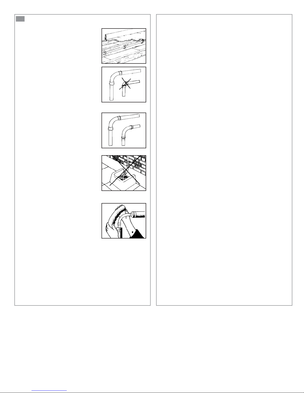
PIPE SUPPORTS
All sanitary pipe work must be
supported, in accordance with the pipe
manufacturer’s recommendations.
Avoid dipping or trapping, which may
cause the build up of residual “solids”
and sub- sequent blockage.
BENDS
Where possible long sweeping bends
should be used. Do not use short
elbows. If sweeping 90° elbows are not
available use two 45° elbows to make
a 90° turn.
PIPE WORK
All pipe work should be either copper,
PVC or CPVC (Do not use flexible
pipes). Hangers should not be less than
four feet apart to prevent pipe rattling.
DISCHARGE
Never discharge directly into an open
drain, fixture, manhole or rainwater
drainpipe. It is illegal for it constitutes a
health hazard. Direct connections into
sanitary waste systems only, shall be
acceptable.
VERTICAL INSTALLATION FIRST
If vertical lift is required, this must precede the horizontal pipe
run.
EASY ACCESS
The unit should be accessible and removable in the event of
maintenance being required. During the installation a full-port
ball valve should be installed at the base of any vertical
discharge pipe work from the unit to allow easy service of
the unit.
GRAVITY FALL
The unit accepts wastewater by gravity; it does not
“vacuum” in water. All inlet pipe work must have a positive
gravity fall, (
1
/4» per foot). All horizontal piping from the
macerating unit must also have a positive gravity fall to allow
free drainage when the pump stops.
NO DIAGONAL “UPHILL” PIPE RUNS
All discharge pipe work from the unit should run either
directly vertical upwards from it or in a horizontal plane
(with a small gravity flow) to the point of discharge.
Pipe work should not be installed with diagonal upward
slope from the unit to the point of discharge.
FREEZING
Ensure all pipe work susceptible to
freezing is adequately insulated or
heated. In unheated buildings, the toilet,
piping and macerating unit must be
properly winterized with “RV or
plumbers” anti-freeze or drained
completely.
ELECTRICITY
Before attempting any maintenance or servicing, the unit must
be disconnected from the power source. The macerating
system must be connected to a Ground Fault Circuit
Interrupter.

LIMITED WARRANTY
Warranty period two-year from date of purchase
Subject to the conditions listed below, SFA-SANIFLO INC. (hereinafter called the «Company»)
guarantees to repair or at its option replace the product or any component thereof, which, in the
opinion of the Company, is faulty or below standard as a result of inferior workmanship or materials.
CONDITIONS
The conditions of this guarantee are:
1. The product must not have been subjected to misuse, neglect, accident or damaging
products, in accordance with the paragraph «USAGE» of these Installation Instructions.
2.The product must have been connected to a single phase 120V, 60Hz electrical supply.
3.The alleged fault or defect must be notified to the company, within the warranty period.
PART OR PRODUCT EXCHANGE
The product will be exchange, free of charge, at the original resellers place of business only, upon
the followings conditions being fullfilled:
1 The customer need a «return authorization» number from the company to authorize and
validate the exchange.
2 The customer must supply a copy of their invoice to validate the request for an exchange.
LIMITATIONS
1.Fill and flush mechanism are guaranteed as per OEM warranty only.
2. Cost of disconnection and reconnection (ie labor charges) are not covered by the warranty
and are end-users responsability.
3. Cost of mail or freight when a part or parts of the system have to be repaired at the
company are not covered by this warranty.
4. In no event shall the company be reliable for any special, incidental or consequential
damage, loss, or injury of whatsoever nature or kind arising from or in connection with the
product or any component thereof.
5. The guarantee is transferable only when the product remains at the same premises as
where it was installed initialy.
Except as set forth in this Limited Warranty, the company disclaims all other warranties, express
or implied, with respect to the product or any component thereof including, but not limited to, all
implied warranties for merchantability and fitness for a particular purpose
For service or for further inquiries, please call or contact any of the following addresses:
United States Canada
SFA-SANIFLO INC. SFA-SANIFLO INC.
105 Newfield Avenue, Suite A
Edison, NJ 08837
Toll Free: 1-800-571-8191 Toll Free: 1-800-363-5874 English
Toll Free: 1-800-877-8538 French
Telephone: 1-732-225-6070 Telephone: 1-519-824-1134
Fax: 1-732-225-6072 Fax: 1-519-824-1143
E-mail.:
Web Site: www.saniflo.com Web Site: www.saniflo.ca
sfasales@saniflo.com
1-685 Speedvale Avenue West
Guelph ON
N1K 1E6
E-mail.:
sales@saniflo.com

1
AVERTISSEMENT
Cet appareil est une pompe de relevage pour eaux usées
provenant d’une douche et d’un lavabo. Il démarre
automatiquement. SANISWIFT® peut également relever
les eaux usées de buanderies, d’éviers, de laveuse à linge
(indirecte seulement) ou lave-vaisselle domestiques et de
baignoire.
Attention : Ne pas utiliser de soupape d’admission d’air ou de
système d’évent mécanique à ressort, car il s’agit d’évents
unidirectionnels. La pression atmosphérique doit être égale
à l’intérieur et à l’extérieur du réservoir. Un «faux» évent
empêche la circulation de l’air dans une direction.
6f
RACCORDEMENT ÉLECTRIQUE
CONNECTER À UNE PRISE RELIÉE À LA TERRE
2
PIÈCES DÉTACHÉES
Voir fig. n°2 page 2.
3
DIMENSIONS
Voir fig. n° 3 page 2.
4
COURBE DE RELEVAGE
Voir fig. n°4 page 2.
5
HAUTEUR DE RELEVAGE
Voir fig. n°5 page 2.
6
INSTALLATION
La pompe possède des dispositifs de fixation l’empêchant de
tourner ou de bouger. La pompe doit être installée suivant les
instructions du manuel d’installation. Prévoir un accès facile
pour la réparation et la maintenance. La pompe doit être
installée en accord avec les codes de plomberie locaux :
CSA B45.9; ASME A112.3.4
6a
RACCORDEMENT AUX ENTRÉES LATÉRALES
Pour les raccordements aux entrées latérales de la cuve,
utilisez des adaptateurs femelle 40 en PVC 11/2. Pensez à
boucher l’entrée non utilisée en y vissant le bouchon.
6b
RACCORDEMENT AUX ENTRÉES SUPÉRIEURES
A l’aide d’un couteau ou d’une scie à métaux, découper avec
soin l’opercule choisi. Veiller à ne pas faire d’entaille à angle vif
et bien ébavurer.
Attention : le trou découpé doit être parfaitement lisse pour
que la liaison soit étanche.
6c
RACCORDEMENT AUX APPAREILS SANITAIRES
Pour raccorder une baignoire (ou une douche), veillez à
surélever le fond d’au moins 8 po. Bien que normalement pas
nécessaire, une ventilation peut être raccordée sur une gaine
de ventilation. (Utilisez une des deux entrées couvercle)
6d
RACCORDEMENT À L’ÉVACUATION
L’évacuation des appareils doit être réalisée avec des tuyaux
de diamètre 1 po en cuivre ou en plastique (PVC, CPVC, etc…).
Cette pompe est étudiée pour évacuer des particules de 3/8”
maximum.
Le raccordement à la colonne de renvoi ou au tuyau
d’égout doit être fait avec un raccord en Y approuvé à cette fin.
En cas de doute, faites faire l’installation par un plombier.
Enfoncez le clapet dans l’ouverture, et fixez en place à l’aide
d’un collier de fixation.
1
Inclinez d’au moins
/4 po par pied, les parties horizontales
d’évacuation jusqu’à la colonne d’évacuation gravitaire.
En bas de la conduite d’évacuation remontante, prévoir une
purge pour permettre la vidange en cas d’intervention.
6e
RACCORDEMENT À UN SYSTÈME D’AÉRATION
SANISWIFT
®
est conçu pour être relié à un système d’aération comme l’exigent les codes locaux. Sur le couvercle de
l’appareil il y a une deuxième entrée. Raccordez avec un tuyau
d’aération en PVC ou en ABS de 11/2 po. Fixez avec des
colliers.
ATTENTION : RISQUE DE CHOC ÉLECTRIQUE. CETTE
POMPE EST FOURNIE AVEC UNE PRISE ET UN
CONDUCTEUR DE TERRE. POUR RÉDUIRE LE RISQUE
ÉLECTRIQUE, VÉRIFIEZ QUE LE BRANCHEMENT EST
CORRECTEMENT RELIÉ À LA TERRE.
Tous les branchements électriques doivent être conformes au
code de l’électricité en vigueur dans votre région. La pompe
requiert une alimentation monophasée de 120 V, 15 A.
La prise de courant doit être située à une distance minimum
de 40 po d’une douche ou d’une baignoire. Ne connectez
l’appareil qu’à une prise de courant protégée par un
coupe-circuit en cas de défaut de terre (GFI).
7
NORMES
Les produits satisfont aux conditions requises pour porter
la CSA Mark Shown, avec les sigles adjoints «C» et «US».
Les sigles «C» et «US» adjoints à la CSA Mark signifient que le
produit a été évalué d’après les normes CSA (CAN) et ANSI/
UL applicables pour une utilisation sur le territoire du Canada
et des Etats-Unis. Ceci inclut les produits satisfaisant aux
conditions requises pour porter la mention NTRL.
La mention NTRL, Nationally Recognized Testing Laboratory
(laboratoire d’essai reconnu nationalement), est une appellation
décernée par la Occupational Safety and Health Administration
(OSHA) (Agence pour la sécurité et la santé au travail)
américaine aux laboratoires comme ayant l’autorité d’accorder
la certification selon les normes américaines.
8
UTILISATION
SANISWIFT® est conçu pour évacuer les eaux usées
provenant d’éviers, de laveuse a linge (indirecte seulement),
de lave-vaisselle, douches ou baignoires.
Attention : ne pas jeter dans les appareils sanitaires raccordés
au SANISWIFT® des produits tels que solvants, peintures,
soude caustique, acides ou autres produits chimiques et la
graisse de cuisine.
Suivant l’usage qui est fait de cet appareil, un nettoyage peut
être nécessaire de temps en temps. Une accumulation de
graisse peut résulter d’un usage intensif.
SANISWIFT® peut pomper des eaux ayant une température
maximum de 140°F (60°C). Si l’appareil pompe des eaux ayant
une température supérieure pendant une période prolongée, la
protection thermique s’enclenche automatiquement et l’appareil
ne pompe plus. Dans ce cas, attendre le refroidissement
(environ 1 heure) pour qu’il redémarre automatiquement.
Cette pompe ne convient pas aux installations souterraines et
ne doit pas être installée dans des lieux dangereux.
9
DÉMONTAGE
(instructions réservées uniquement aux professionnels)
Débrancher l’alimentation électrique avant toute intervention
sur l’appareil. Cet appareil ne nécessite pas de maintenance
particulière. En cas de panne, toute intervention sur l’appareil
devra être effectuée par un dépanneur agréé Saniflo.
En particulier l’échange du cordon d’alimentation.
10
GARANTIE
SANISWIFT® est garanti 2 ans sous réserve d’une installation
et d’une utilisation correctes de l’appareil et conformes aux
instructions de cette notice.

11
GUIDE DE DÉPANNAGE
PROBLÈME
Le moteur tourne normalement,
mais l’eau s’évacue lentement.
L’eau s’évacue lentement
et le moteur fonctionne par
intermittence.
La pompe ne démarre pas.
L’eau ne s’évacue pas.
Le moteur ronronne, mais ne
tourne pas. L’eau ne s’évacue
pas.
L’eau s’évacue mais le moteur
fonctionne très longtemps et le
rupteur thermique est activé.
Après l’évacuation, le moteur
redémarre plusieurs fois avant de
s’arrêter complètement.
Le moteur tourne bruyamment,
sans s’arrêter ni pomper.
CAUSE
Le tuyau d’évacuation ou le clapet sont bouchés ; ou la vanne de
sortie est à moitié fermée.
Colonne de ventilation bouchée.
Le courant est coupé. Le rupteur
thermique ne fonctionne pas.
Un corps étranger bloque la
pompe. Condensateur défectueux.
Tuyau d’évacuation bouché ou
tordu. Pompe partiellement
bloquée.
L’eau est renvoyée dans la
pompe.
Le clapet antiretour ne fonctionne
pas bien.
Siphonnage ou manque de
contrepression dans le tuyau de
vidange, causant une poche d’air.
Présence d’un corps étranger.
SOLUTION
Nettoyez le tuyau et le clapet.
Vérifiez la vanne de sortie.
Nettoyez la colonne de
ventilation.
Attendez que le rupteur thermique fonctionne (environ 20
minutes).
Consultez un technicien agréé.
Consultez un technicien agréé.
Tirez la chasse d’eau 1 ou 2 fois
avec de l’eau claire pour dégager
le clapet ou enlevez le clapet et
nettoyez-le.
Modifiez la tuyauterie d’évacuation de manière à éliminer le
siphonnage ou à augmenter la
contrepression (p. ex., utilisez
des tuyaux plus petits, ajoutez
une courbe de tuyau). Si le
problème persiste, consultez
un technicien agréé.
Le moteur tourne, mais fait un
bruit étrange.
L’eau remonte dans la baignoire
ou la cabine de douche.
Un corps solide est tombé dans
la pompe.
L’écoulement par gravité dans
la pompe n’est pas adéquat.
Clapet d’entrée défectueux.
Consultez un technicien agréé.
Assurez-vous qu’il y a un
écoulement par gravité d’au
moins
1
/4 po à 12 po entre les
autres appareils sanitaires
et la pompe.
Nettoyez les clapets d’entrées.
12
CONSEILS
ANCRAGE DES TUYAUX
Tous les tuyaux des installations sanitaires doivent être ancrés conformément
aux recommandations du fabricant pour
les empêcher de pendre, car ils pourraient alors être bloqués par une accumulation de “matières solides ”.
COURBES
Dans la mesure du possible, utilisez des
courbes de tuyau plutôt que des coudes.
Si des coudes de 90° ne sont pas disponibles, utilisez deux coudes de 45° pour
former une courbe de 90°.
TUYAUTERIE
Tous les tuyaux doivent être en cuivre ou
en plastique soudé au solvant. Il ne faut
pas utiliser de tuyaux flexibles. Les
pendards doivent être espacés d’au
moins quatre pieds pour empêcher les
tuyaux de cogner.
VIDANGE
Ne jamais évacuer les eaux usées directement dans un égout à ciel ouvert, un
trou d’homme ou un drain pour les eaux
de pluie. Cela est illégal et constitue un
danger pour la santé. Seuls les branchements directs dans les systèmes de
déchets sanitaires sont acceptables.
LA TUYAUTERIE VERTICALE D’ABORD
Lorsqu’on installe des tuyaux à la verticale, il faut les poser avant
de poser les tuyaux horizontaux.
ACCÈS FACILE
Il faut avoir accès à l’ensemble broyeur-pompe et pouvoir le
déposer en cas de réparation. Au moment de l’installation, il faut
poser une purge et une vanne d’arrêt à passage intégral à la
base de tout tuyau d’évacuation vertical, pour permettre de
réparer facilement l’appareil.
DESCENTE PAR GRAVITÉ
Les eaux usées se déversent dans
l’ensemble broyeur-pompe par gravité. Elles ne sont pas
aspirées. Tous les tuyaux d’arrivée doivent assurer l’écoulement
absolu par gravité (
horizontaux
sortant de l’ensemble broyeur-pompe
doivent aussi assurer l’écoulement absolu par gravité, pour que
le drainage se fasse librement lorsque la pompe s’arrête.
1/4 po par pied). Les tuyaux d’évacuation
PAS DE TUYAUX EN DIAGONALE
Tous les tuyaux de vidange sortant de l’appareil doivent soit
monter directement à la verticale, soit être en position horizontale (avec un léger écoulement par gravité) jusqu’au point
d’évacuation. Il ne faut pas installer de tuyaux en diagonale
entre l’appareil et le point d’évacuation.
GEL
Assurez-vous que tout tuyau susceptible
de geler est bien isolé ou chauffé. Dans
les immeubles non chauffés, la toilette, la
tuyauterie et l’ensemble broyeur-pompe
doivent être protégés contre le gel avec
de l’antigel de « véhicule de plaisance »
ou vidés complètement.
ELECTRICITÉ
Avant d’entreprendre des travaux d’entretien ou de dépannage, il
faut débrancher l’appareil de la source d’alimentation en électricité. Le système de broyage doit être protégé par un coupe-circuit
en cas de défaut de mise à la terre du neutre.

GARANTIE LIMITÉE
Garantie de deux ans à partir de la date d’achat
Sous réserve du respect des conditions énoncées ci-dessous, SFA-SANIFLO INC. (ci-dessous appelée “la
Compagnie”) garantit qu’elle réparera ou remplacera, à son gré, le produit ou l’une quelconque de ses pièces,
qui de l’avis de la Compagnie, se trouve défectueux ou ne répond pas à la performance demandée du fait d’un
défaut de fabrication ou de matériau.
CONDITIONS
Les conditions de la garantie sont :
1. Le produit ne doit pas avoir subi de mauvais traitement, de négligence, d’accident ou d’exposition à
des produits nocifs, conformément au paragraphe intitulé «UTILISATION»;
2. Le produit doit avoir été branché à une prise de courant monophase 120V, 60Hz ;
3. Le présumé défaut ou la présumée défaillance doit être signalé (e), sinon à l’installateur, du moins à
la Compagnie, durant la période de garantie en vigueur.
ÉCHANGE DE PIÈCE OU DE PRODUIT
Le produit sera échangé sans frais, à l’établissement de détail où il a été acheté seulement, sous réserve du
respect des conditions suivantes :
- Le client devra être en possession d’un numéro «d’autorisation de retour» de la Compagnie afin
d’autoriser et de valider l’échange ;
- Le client doit fournir une copie de sa facture pour valider la demande d’échange.
RESTRICTIONS
1. Les mécanismes de chasse et de remplissage du réservoir sont garantis par le fabricant d’origine
seulement ;
2. La garantie ne couvre pas les frais de branchement et rebranchement de l’installation (c.-à-d. les
frais de main-d’œuvre) qui sont à la charge du client ;
3. La garantie ne couvre pas les frais d’expédition ou de transport quand une pièce ou des pièces de
l’appareil doit(vent) être réparé(e)s à l’usine ;
4. En aucun cas la Compagnie ne sera tenue responsable des dommages accessoires ou indirects,
pertes ou blessures, de quelle que nature que ce soit, résultant de l’utilisation du produit, ou de l’un
de ses composants ;
5. La garantie est transférable seulement si l’appareil demeure à l’endroit où il fut installé initialement.
Sauf pour ce qui est des termes de cette garantie limitée, la Compagnie n’accepte aucune autre garantie,
implicite ou explicite, ayant trait au produit ou à tout composant y afférent, incluant sans toutefois s’y limiter,
toute autre garantie implicite quant à la valeur marchande ou l’adaptabilité de ce produit à une fin particulière.
Pour le service et d’autres demandes de renseignements, veuillez appeler à l’une des adresses indiquées
ci-dessous.
États-Unis Canada
SFA-SANIFLO INC. SFA-SANIFLO INC.
105 Newfield Avenue, Suite A
Edison, NJ 08837
1-685 Speedvale Avenue West
Guelph ON
N1K 1E6
Numéro sans frais : 800-571-8191 Numéro sans frais : 800-363-5874 Anglais
Numéro sans frais : 800-877-8538 Français
Téléphone : 732-225-6070 Téléphone : 519-824-1134
Télécopie : 732-225-6072 Télécopie : 519-824-1143
C.élec. :
Site Web : www.saniflo.com Site Web : www.saniflo.ca
sfasales@saniflo.com
C.élec. :
sales@saniflo.com
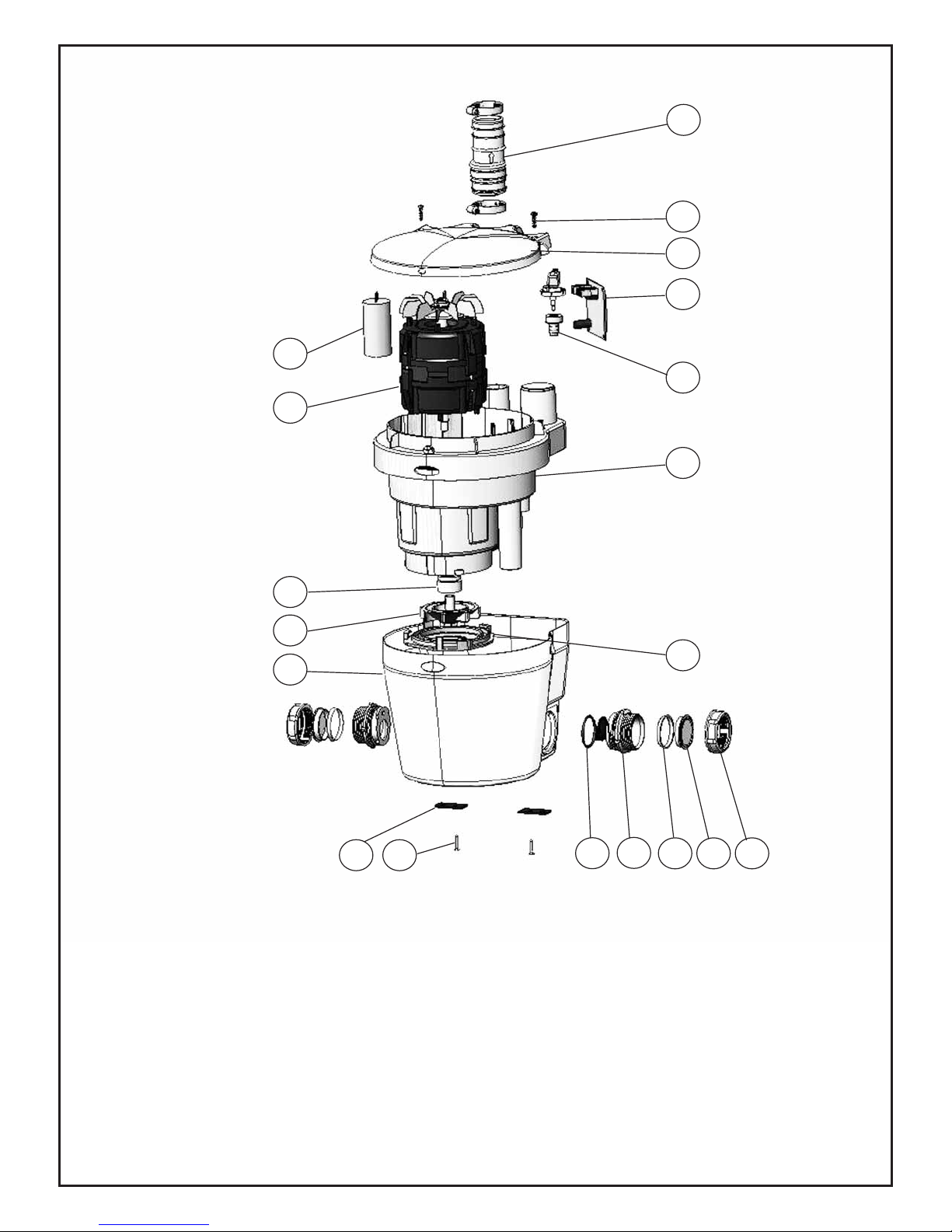
EXPLODED DRAWING / DESSIN ÉCLATÉ
1
2
3
4
5
6
7
8
14
15
17
23
24
21
22
16
20
19
18

CANADA
✄
CANADA
✄
USA

✄
G6
03.07
G7
03.07
✄
G8
03.07
 Loading...