


SFAR-S-ETH
User Manual
Expansion Module – Gateway Modbus TCP
Global Control 5 Sp. z o.o.
Warsaw, Poland
www.gc5.pl

SFAR-S-ETH User Manual
Version 3.0 www.gc5.pl Page 2 / 27
Table of contents
1. Safety rules .................................................................................................................................... 4
2. Module features ............................................................................................................................ 4
2.1. Purpose and description of the module .......................................................................... 4
2.2. Technical specifications ..................................................................................................... 5
2.3. Dimensions of the product ................................................................................................ 6
3. Configuration of the communication ........................................................................................ 7
3.1. Grounding and shielding .................................................................................................... 7
3.2. Network termination ........................................................................................................... 7
3.3. Setting Module Address in RS485 Modbus Network ................................................... 7
3.4. Types of Modbus Registers ............................................................................................... 8
3.5. Communication settings .................................................................................................... 8
3.5.1. Default settings ............................................................................................................ 9
3.5.2. Restore the default configuration ............................................................................. 9
3.5.3. Configuration registers ............................................................................................. 10
3.5.4. Watchdog information .............................................................................................. 10
4. Indicators ...................................................................................................................................... 11
5. Module connection ..................................................................................................................... 11
5.1. Block diagram..................................................................................................................... 11
5.2. Connection of digital inputs ............................................................................................. 12
5.3. Connection of relay outputs ............................................................................................ 12
5.3.1. Connection of resistive load .................................................................................... 12
5.3.2. Connection of electrovalve ....................................................................................... 12
5.4. Quick Connect .................................................................................................................... 13
6. Switches ....................................................................................................................................... 14
7. Modules Registers ...................................................................................................................... 14
7.1. Registered access ............................................................................................................. 14
7.2. Bit access ............................................................................................................................ 17
8. Configuration software .............................................................................................................. 18
9. Web page ...................................................................................................................................... 19
9.1. Login ..................................................................................................................................... 19
9.2. Info ........................................................................................................................................ 20
9.3. Network ............................................................................................................................... 21
9.4. Modbus Config ................................................................................................................... 22
9.5. Local I/O .............................................................................................................................. 23
9.6. Device Table ....................................................................................................................... 24
10. Modbus TCP working modes ................................................................................................... 26
10.1. Gateway Modbus TCP ...................................................................................................... 26
10.2. Device Table ....................................................................................................................... 27

SFAR-S-ETH User Manual
Version 3.0 www.gc5.pl Page 3 / 27
Thank you for choosing our product.
This manual will help you with proper handling and operating of the device.
The information included in this manual have been prepared with utmost care by our
professionals and serve as a description of the product without incurring any liability for the
purposes of commercial law.
This information does not discharge you from the liability of your own judgment and
verification.
We reserve the right to change product specifications without notice.
Please read the instructions carefully and follow the recommendations concluded therein.
WARNING!
Failure to follow instructions can result in equipment damage or impede the use of the
hardware or software.

SFAR-S-ETH User Manual
Version 3.0 www.gc5.pl Page 4 / 27
1. Safety rules
1. Refer to this manual before the first use
2. Make sure that all cables are connected properly before the first use
3. Please ensure proper working conditions, according to the device specifications
(e.g., supply voltage, temperature, maximum power consumption)
4. Turn the power supply off before making any modifications to wiring connections.
2. Module features
2.1. Purpose and description of the module
ETH module is an innovative device converting Modbus TCP into Modbus RTU/ASCII.
The device is equipped with the Ethernet and RS485 interface, 4 Digital Inputs with counters
and 3 Relay Outputs. All the inputs are insulated from logic with the aid of optoisolators.
The communication takes place with the benefit of Modbus TCP protocol. Every received
request from the Modbus TCP client is checked considering the address. If the address is
different than the SFAR-S-ETH device address, automatic conversion of the request frame
into the Modbus RTU/ASCII protocol ensues. Later on, the correctly received answer is sent
to the Modbus TCP client.
The usage of a 32-bit processor with ARM core assures fast data processing and smart
communication.
The new function called Modbus Device Table allows the user to define their own enquiries
to Modbus ATU/ASCII from the accessible internal registries of the device. This function
allows to e.g. automatic reading of the statuses of the modules’ inputs on RS485 and
inscribing these statuses into the SFAR-S-ETH internal registries. Internal registries are
accessible for the Modbus TCP clients without additional delays resulting from the RS485
bus. This solution strongly accelerates the communication. All the bit orders and registry
orders of the MODBUS protocol are available.
The module is designed for mounting on a DIN rail in accordance with DIN EN 5002.

SFAR-S-ETH User Manual
Version 3.0 www.gc5.pl Page 5 / 27
The module is equipped with a set of LEDs to indicate the status of inputs and outputs which
is useful for diagnostic purposes and helping to find errors.
Module configuration is done via built-in website or USB by using a dedicated computer
program. You can also change the parameters using the MODBUS protocol.
2.2. Technical specifications
Power Supply
Voltage
10-38 V DC; 10-28 V AC
Power consumption1
7 W @ 24 V DC
9 VA @ 24 V AC
Digital inputs
No. of inputs
4
Voltge range
0 – 36 V
Low state „0”
0 – 3 V
High state „1”
4 – 36 V
Input impedance
4 kΩ
Isolation
3750 Vrms
Inputs type
PNP lub NPN
Counters
No.
4
Resolution
32 bits
Frequency
1 kHz (max)
Impulse Width
500 µs (min)
Relay outputs
No. of outputs
3
Maximum current and voltage
(resistive load)
3 A 230 V AC
3 A 30 V DC
Temperature
Work
-20°C - +65°C
Storage
-40°C - +85°C
Connectors
Power supply
2 pin
Communication RS485
3 pin
Communication Ethernet
RJ45
1
Power consumption with active Modbus transmission, all outputs on and high state on all inputs
SFAR-S-ETH User Manual
Version 3.0 www.gc5.pl Page 6 / 27
Inputs and outputs
2 x 5 pin
Quick connector
IDC10
Configuration
Mini USB
Size
Height
119.1 mm
Length
110 mm
Width
22.6 mm
Interface
Ethernet
10/100 Mbps
RS485
Up to 128 devices
Table 1 - Technical specifications
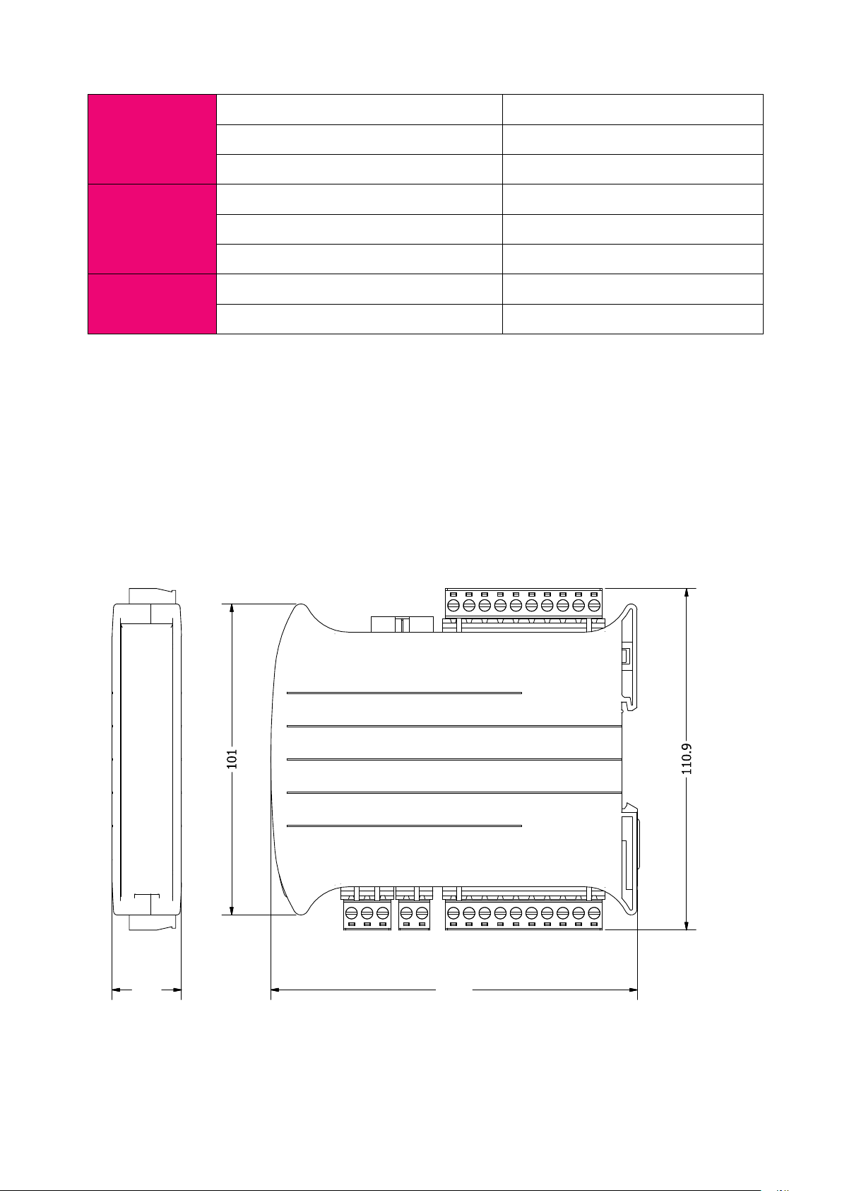
2.3. Dimensions of the product
The appearance and dimensions of the module are shown below. The module is mounted
directly to the rail in the DIN industry standard. Power connectors, communication and IOs
are at the bottom and top of the module. USB connector configuration and indicators are
located on the front of the module.
Picture 1 - Dimensions of the product

SFAR-S-ETH User Manual
Version 3.0 www.gc5.pl Page 7 / 27
3. Configuration of the communication
3.1. Grounding and shielding
In most cases, IO modules will be installed in an enclosure along with other devices which
generate electromagnetic radiation. Examples of these devices are relays and contactors,
transformers, motor controllers etc. This electromagnetic radiation can induce electrical
noise into both power and signal lines, as well as direct radiation into the module causing
negative effects on the system. Appropriate grounding, shielding and other protective steps
should be taken at the installation stage to prevent these effects. These protective steps
include control cabinet grounding, module grounding, cable shield grounding, protective
elements for electromagnetic switching devices, correct wiring as well as consideration of
cable types and their cross sections.
3.2. Network termination
Transmission line effects often represent the problem on data communication networks.
These problems include reflections and signal attenuation.
To eliminate the presence of reflections at the end of the cable, the cable must be terminated
at both ends with a resistor across the line equal to its characteristic impedance. Both ends
must be terminated since the direction of propagation is bi-directional. In the case of RS485
twisted pair cable this termination is typically 120 Ω.
3.3. Setting Module Address in RS485 Modbus Network
Changing the address of the SFAR-S-ETH is possible with the aid of an inbuilt www website.
After logging in, one should choose the tab Network, insert the module address in the Device
Address field and click Save. The device will save the given address and will remember it even
after disconnecting from the power supply (more details in 9.4 - Modbus Config).
Attention! The address is reset during the restoration of default configuration (more details
in 3.5.1 – Default settings).

SFAR-S-ETH User Manual
Version 3.0 www.gc5.pl Page 8 / 27
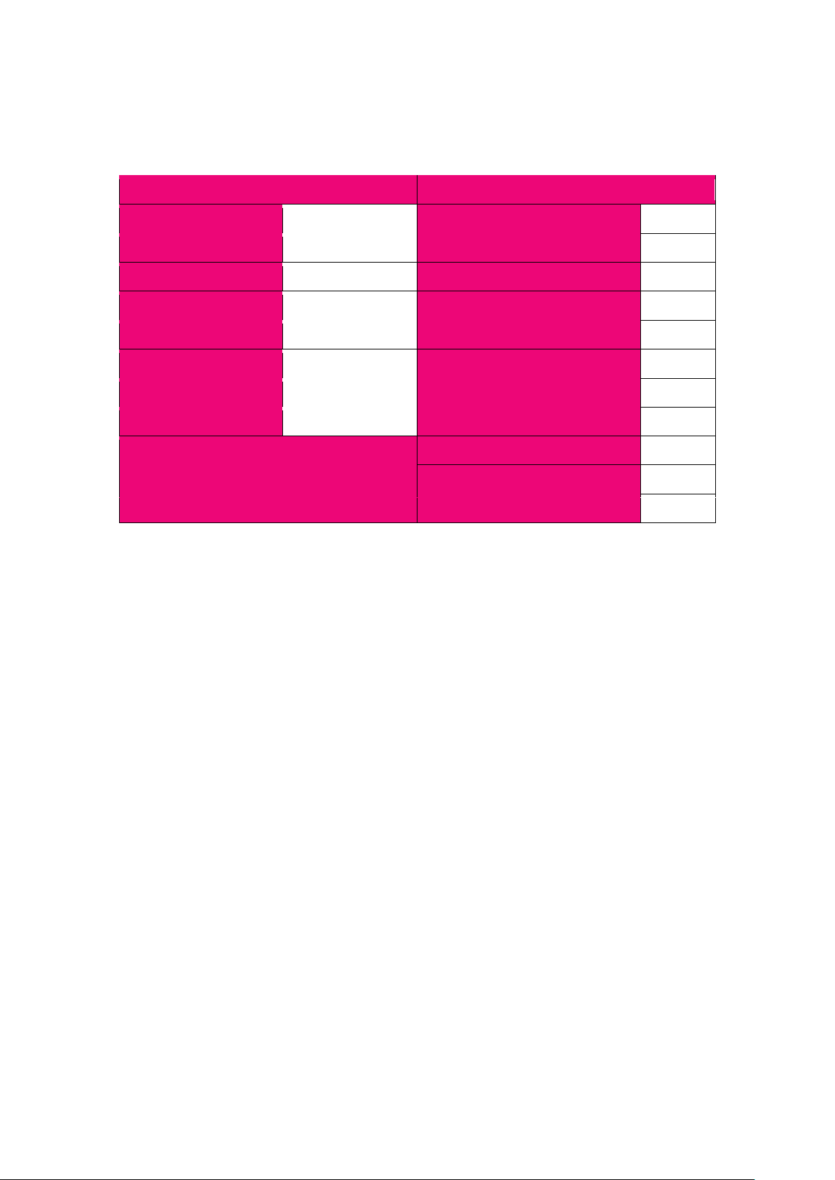
3.4. Types of Modbus Registers
There are 4 types of variables available in the module.
Type
Beginning address
Variable
Access
Modbus
Command
1
00001
Digital Outputs
Bit
Read & Write
1, 5, 15
2
10001
Digital Inputs
Bit
Read
2
3
30001
Input Registers
Registered
Read
3
4
40001
Output Registers
Registered
Read & Write
4, 6, 16
Table 3 - Types of variables
3.5. Communication settings
The settings of TCP communication are stored in memory of the device. The Modbus TCP
network configuration is only accessible through the www website (more details in 9.3. –
Network). The communication data of the module in RS485 network is stored in the16-bit
registries. The access to the registries is possible with the benefit of Modbus TCP protocol
or through the www website (details in 9.4 - Modbus Config).
SFAR-S-ETH User Manual
Version 3.0 www.gc5.pl Page 9 / 27
3.5.1. Default settings
You can restore the default configuration by the switch SW6 (see 3.5.2. )
Modbus TCP
Modbus RTU/ASCII
Address IP
192.168.1.135
Transmission speed
19200
Mask
255.255.255.0
Parity
No
Gateway
192.168.1.1
The amount of data bits
8
Port Modbus
502
The amount of stop bits
1
Port HTTP
80
Modbus mode
RTU
Timeout of connection
60 s
The device address
1
Login
admin
Timeout of RS485
500 ms
Password
0000
Mode
Gateway
Device Table Refresh Slow
10000 ms
Device Table Refresh Normal
2000 ms
Device Table Refresh Fast
500 ms
Table 4 - Default settings
3.5.2. Restore the default configuration
To restore the default configuration:
• Turn the power off
• Turn the switch sw6 on
• Turn the power on
• When power and communication led flash turn the switch sw6 off
WARNING! After restoring the default configuration all values stored in the registers will be
cleared as well.

SFAR-S-ETH User Manual
Version 3.0 www.gc5.pl Page 10 / 27
3.5.3. Configuration registers
Address
Modbus
Address
Dec
Address
Hex
Name
Values
40003
2
0x02
Baud rate
0 – 2400
1 – 4800
2 – 9600
3 – 19200
4 – 38400
5 – 57600
6 – 115200
other – value * 10
40005
4
0x04
Parity
0 – none
1 – odd
2 – even
3 – always 1
4 – always 0
40004
3
0x03
Stop Bits LSB
1 – one stop bit
2 – two stop bits
40004
3
0x03
Data Bits MSB
7 – 7 data bits
8 – 8 data bits
40007
6
0x06
Modbus Mode
0 – RTU
1 – ASCII
Table 5 - configuration registers
3.5.4. Watchdog information
This 16-bits register specifies the time in milliseconds to watchdog reset. If module does not
receive any valid message within that time, all Digital and Analog Outputs will be set to the
default state.
This feature is useful if there is an interruption in data transmission and for security reasons.
Output states must be set to the appropriate state in order to reassure the safety of persons
or property.
The default value is 0 milliseconds which means the watchdog function is disabled.

SFAR-S-ETH User Manual
Version 3.0 www.gc5.pl Page 11 / 27
4. Indicators
Indicator
Description
Power supply
LED indicates that the module is correctly powered.
Communication
The LED lights up when the unit received the correct packet Modbus TCP, converted to
Modbus RTU/ASCII and sent it over the RS485 network.
Inputs state
LED indicates that the input is on.
Outputs state
LED indicates that the output is on.
Table 6 - Description of indicators
5. Module connection
5.1. Block diagram
Picture 2 – Indicators
Picture 3 – Block diagram

SFAR-S-ETH User Manual
Version 3.0 www.gc5.pl Page 12 / 27
5.2. Connection of digital inputs
5.3. Connection of relay outputs
5.3.1. Connection of resistive load
5.3.2. Connection of electrovalve
Picture 5 – Connection of input
Picture 6 – Connection of resistive load
Picture 7 – Connection of electrovalve

SFAR-S-ETH User Manual
Version 3.0 www.gc5.pl Page 13 / 27
5.4. Quick Connect
Quick Connect is an unique feature of modules that allows you to quickly connect group of
devices with a flat ribbon cable. Thanks to this solution, it is enough to connect power and
RS485 communication to one of the devices in the group and the others will be powered and
communicated with ribbon cable.
The Quick Connect is sufficient to connect up to 10 devices next to each other. What is
important that the various types of modules in the SFAR-S family can be connected with
the ribbon cable.
Picture 8 – Connection of Quick connect
SFAR-S-ETH User Manual
Version 3.0 www.gc5.pl Page 14 / 27
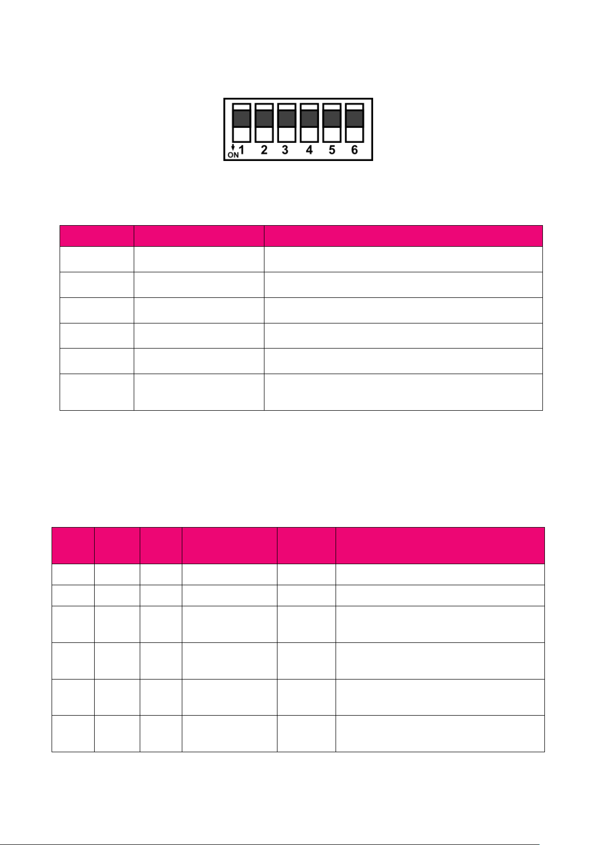
6. Switches
Switch
Function
Description
1
None
2
None
3
Bias Pull Up
Switching pull-up resistor
4
Bias Pull Down
Switching pull-down resistor
5
Network Termination
Switching terminating resistor 120Ω
6
Restoring default settings
Restoring default settings
Table 7 - Description of switches
7. Modules Registers
7.1. Registered access
Address
Modbus
Address
Dec
Address
Hex
Register Name
Access
Description
30001
0
0x00
Version/Type
Read
Version and Type of the device
30002
1
0x01
Address
Read
Module address SFAR-S-ETH
40003
2
0x02
Baud rate
Read &
Write
Transmission speed
40004
3
0x03
Stop bits
Read &
Write
Stop bits
40005
4
0x04
Parity
Read &
Write
Parity
40007
6
0x06
Modbus Mode
Read &
Write
Modbus protocol type
Picture 9- Switches

SFAR-S-ETH User Manual
Version 3.0 www.gc5.pl Page 15 / 27
Address
Modbus
Address
Dec
Address
Hex
Register Name
Access
Description
40009
8
0x08
Watchdog
Read &
Write
Function watchdog for outputs [ms]
40013
12
0x0C
Default Outputs
State
Read &
Write
Default state of outputs
lit bit → output active
40014
13
0x0D
Operating mode
Read &
Write
Modbus mode TCP
0 – Device Table; 1 – Gateway Modbus TCP
40015
14
0x0E
Slow Rate
Read &
Write
Frequency of queries in Device Table mode
[ms]
40016
15
0x0F
Normal Rate
Read &
Write
Frequency of queries in Device Table mode
[ms]
40017
16
0x10
Fast Rate
Read &
Write
Frequency of queries in Device Table mode
[ms]
40033
32
0x20
Received packets
MSB
Read &
Write
The amount of received packets
40034
33
0x21
Received packets
LSB
Read &
Write
40035
34
0x22
Incorrect packets
MSB
Read &
Write
The amount of received incorrect packets
40036
35
0x23
Incorrect packets
LSB
Read &
Write
40037
36
0x24
Sent packets MSB
Read &
Write
The amount of sent packets
40038
37
0x25
Sent packets LSB
Read &
Write
30051
50
0x32
Inputs
Read
Inputs status
lit bit → input active
40052
51
0x33
Outputs
Read &
Write
Outputs status
40053
52
0x34
Counter 0 MSB
Read &
Write
32-bits counter 0
40054
53
0x35
Counter 0 LSB
Read &
Write
40055
54
0x36
Counter 1 MSB
Read &
Write
32-bits counter 1
40056
55
0x37
Counter 1 LSB
Read &
Write

SFAR-S-ETH User Manual
Version 3.0 www.gc5.pl Page 16 / 27
Address
Modbus
Address
Dec
Address
Hex
Register Name
Access
Description
40057
56
0x38
Counter 2 MSB
Read &
Write
32-bits counter 2
40058
57
0x39
Counter 2 LSB
Read &
Write
40059
58
0x3A
Counter 3 MSB
Read &
Write
32-bits counter 3
40060
59
0x3B
Counter 3 LSB
Read &
Write
40061
60
0x3C
Reset counters
Read &
Write
Reset counters
lit bit → counter reset
Table 8 - Registered access

SFAR-S-ETH User Manual
Version 3.0 www.gc5.pl Page 17 / 27
7.2. Bit access
Address
Modbus
Address
Dec
Address
Hex
Register name
Access
Description
193
192
0x0C0
Default state of output 1
Read &
Write
Default state of output 1
194
193
0x0C1
Default state of output 2
Read &
Write
Default state of output 2
195
194
0x0C2
Default state of output 3
Read &
Write
Default state of output 3
801
800
0x320
Input 1
Read
Input 1 state
802
801
0x321
Input 2
Read
Input 2 state
803
802
0x322
Input 3
Read
Input 3 state
804
803
0x323
Input 4
Read
Input 4 state
817
816
0x332
Digital output 1
Read &
Write
State of digital output 1
818
817
0x333
Digital output 2
Read &
Write
State of digital output 2
819
818
0x334
Digital output 3
Read &
Write
State of digital output 3
962
961
0x3E0
Reset counter 0
Read &
Write
Reset counter 0
963
962
0x3E1
Reset counter 1
Read &
Write
Reset counter 1
964
963
0x3E2
Reset counter 2
Read &
Write
Reset counter 2
965
964
0x3E3
Reset counter 3
Read &
Write
Reset counter 3
Table 9 - Bit access

SFAR-S-ETH User Manual
Version 3.0 www.gc5.pl Page 18 / 27
8. Configuration software
Modbus Configurator is the type of software which is designed to set the communication
module registers over Modbus network as well as to read and write the current value of other
registers of the module. It’s a convenient way to test the system as well as to observe realtime changes in the registers.
Communication with the module happens via the USB cable. The module does not require
any drivers.
Configurator is a universal software, whereby it is possible to configure all available modules.
Picture 10 -Configuration process
Picture 11- Configurator

SFAR-S-ETH User Manual
Version 3.0 www.gc5.pl Page 19 / 27
9. Web page
The SFAR-S-ETH device has an inbuilt www website, thanks to which the user is able to
control its working. The website allows to the access to the configuration of the TCP and
RS485 networks, up-to-date statuses of inputs and outputs and the settings of the Device
Table mode.
9.1. Login
The access to the website is possible through the browser. IP address should be put in the
address field then Enter button should be pressed. The log-in site appears, in which the login
‘admin’ and the defined password (by default ‘0000’) should be inserted. If the login and the
password are correct, after clicking the Login button the default www website with the Info
tab appears.
The logout takes place if the default website is opened for at least 15 minutes with the tab of
Info, Network or Modbus Config or after clicking the Logout button.
Picture 12 - Login

SFAR-S-ETH User Manual
Version 3.0 www.gc5.pl Page 20 / 27
9.2. Info
The tab Info implies links to the instructions of the device and information about the up-todate version of the software. Changing the password of the access to the www website is
also possible.
In order to change the password user should put the prevailing password in the field Old
Password and then the new one in the fields New Password and Confirm Password. Then
click Change Password button.
Attention! After the re-enacting of default settings, the password is reset (more details in
3.5.1 Default settings).
Picture 13 - Info

SFAR-S-ETH User Manual
Version 3.0 www.gc5.pl Page 21 / 27
9.3. Network
The tab Network serves to the Modbus TCP network configuration. The given parameters are
implied:
• IP – the module’s IP address
• Mask – the network’s mask
• Gateway – the gate
• Modbus Port – the port to connect the PC with TCP Modbus
• HTTP Port – the port to connect with www website
• Connection Timeout – the maximum waiting time for the requests TCP Modbus.
After this time the connection on the Modbus Port will be cut (given in seconds).
In order to confirm the changes, user should click the Save button. In the case of changing
IP, Mask, Gateway, Modbus Port and/or HTTP Port parameters, user should reset the module
to let the changes be implemented. The Reset Device button has been put to reset the device
remotely. After clicking on it, the browser will try to connect with the new IP address and after
a few seconds the log-in website with the prevailing IP address will be loaded.
Attention! After the re-enacting the default settings, all the parameters are reset (more details
in 2.5.1. – Default settings).
Picture 14 - Network

SFAR-S-ETH User Manual
Version 3.0 www.gc5.pl Page 22 / 27
9.4. Modbus Config
In the Modbus Config tab, the configuration of the basic Modbus network parameters for
both of the working modes is possible. The tab implies the parameters of RS485 network to
communicate with external modules
(more details in
3.5.3 Configuration registers), and:
• Device Address – the module’s address in Modbus TCP network,
• RS485 Timeout – the maximum waiting time for the response in the Modbus
RTU/ASCII network (given in milliseconds),
• Device Table Refresh Slow, Normal, Fast – the frequency of refreshing the request in
the Device Table mode (given in milliseconds),
• Mode – the working mode of the module
Picture 15 – Modbus Config

SFAR-S-ETH User Manual
Version 3.0 www.gc5.pl Page 23 / 27
9.5. Local I/O
The Local I/O tab enables to see the preview and to control the digital inputs and outputs of
the device.
Four icons marked as Digital input 1, 2, 3, 4 show the up-to-date status of digital inputs. The
grey colour indicates that the input is inactive and the green colour means that it is active.
Icons marked as Digital output 1, 2, 3 allow to control the outputs. The grey colour indicates
that the particular output is off and the orange colour means that it is on. After clicking on a
particular button, the information about the output’s status is sent to the module.
The status of inputs and outputs is recurrently refreshed, so the icons described above
present the up-to-date status of the inputs and outputs of the device.
In this tab there are also fields showing the status of 4 counters which count the impulses
on the inputs 1, 2, 3 and 4. The fields are read-only and the counters can be only reset with
the aid of the corresponding Reset buttons.
The module also permits to define default statuses of the outputs. On the www website they
can be set analogously to the digital outputs – the grey colour indicates that the default
output is off and the orange colour means that it is on. The default status is assigned after
connecting to a power supply and after the Watchdog time elapse, which is reset after each
correct TCP Modbus package addressed to the SFAR-S-ETH module. If the Watchdog’s value
equals zero, the default statuses are only assigned after connecting the power supply.
Picture 16 – Local IO

SFAR-S-ETH User Manual
Version 3.0 www.gc5.pl Page 24 / 27
9.6. Device Table
The next tab includes configurations for the Device Table mode, which allows to define user’s
own requests Modbus RTU/ASCII from the accessible internal registers of the device.
The first tab called Internal Registers includes the table of internal registers of the SFAR-SETH module, which are recurrently refreshed by www website. These registers are used by
adding remote requests in the Devices tab. After clicking on the Add Device button, a line to
define the request appears. Each line implies the following:
• Device Address – the address of the device in RS485 network, to which the
SFAR-S-ETH module will send the request,
• Function – the Modbus request function,
• Size – the amount of bits/registers to read/save,
• Register Address – the address of the initial register,
• Internal Address – the initial address of the internal register, where the data to
save/read will be stored,
• Speed – the choice of one of the three frequencies read (the values are
configurable in the module’s registers),
• ON/OFF – the active or inactive request,
• Status – presents the status of the request.
Picture 17 - Devices

SFAR-S-ETH User Manual
Version 3.0 www.gc5.pl Page 25 / 27
The configuration of the requests can be saved by the user in an external file and after reading
automatically re-enacted to the device. The configuration is saved in the memory of the
device and is only reset after re-enactment of the default configuration (more details in 3.5.1
- Default settings).
Picture 18 - Internal Registers

SFAR-S-ETH User Manual
Version 3.0 www.gc5.pl Page 26 / 27
10. Modbus TCP working modes
The SFAR-S-ETH module has two different working modes. The first is the TCP Modbus gate,
in which the device converts the frames of Modbus TCP into Modbus RTU/ASCII and sends
them to the RS485 network’s devices.
The second mode is the Device Table function, in which the module read the RS485 network’s
devices only using the earlier-defined requests and ignores the requests addressed to other
devices in the Modbus TCP network. The communication with external modules is only
possible through the internal registers of the module from the addresses 1000-1099.
10.1. Gateway Modbus TCP
The SFAR-S-ETH module in the TCP gate mode serves maximum up to four clients
simultaneously. After connecting to the module in the proper port, the module waits for the
frames which are compatible with the Modbus TCP specification. In the first instance, after
receiving any package on this port, the device checks its correctness. If the length of the
package will be incorrect, the device will send an error with the Modbus code 0x03 – Illegal
Data Value. If the request is correct and addressed to the SFAR-S-ETH module, the function
from the request is executed. If it is not a Modbus function, the device will send the error with
the code 0x04 – Server Device Failure.
After processing the request and preparing the response, the module sends it accordingly to
the Modbus TCP protocol’s specification.
If the request is not addressed to the SFAR-S-ETH module and the TCP gate mode is set, the
device converts the request into the Modbus RTU/ASCII and sends it to RS485 bus. The
SFAR-S-ETH waits for the defined time for the response and blocks the access to the RS485
bus for other clients, to avoid the packages’ conflict. If the module receives the response or
the time is out, the bus is released and in the case of receiving the package on the RS485 it
is checked in terms of compatibility with the RTU or ASCII mode. In the case of a correct
package, it is converted into Modbus TCP and sent to the client. In the case of an error, the
code 0x04 (if the response was not received before the defined time) or the code 0x03 (if the
package is incorrect) is sent. If the module does not get the access to the RS485 network,
the package is sent back with the error code 0x06 – Server Device Busy.

SFAR-S-ETH User Manual
Version 3.0 www.gc5.pl Page 27 / 27
10.2. Device Table
While working in the Device Table mode, the client connects with the device in the same way
as in the case of the gate mode. One considerable difference is that the SFAR-S-ETH module
will ignore all the requests which are not addressed to it. The communication with external
devices is only possible through the configuration of remote requests by the www website
(more details in 9.6 – Device Table) and reading/saving from/to the internal registers of the
SFAR-S-ETH module. Each request is automatically stored in the module’s memory.
If the configuration of the request is correct, the device in this mode asks the modules online
by saving the request and it saves the responses in the internal registers indicated by the
user in the case of reading the data or downloads the data from there registers in the case
of their saving. In the case of incorrectly configured request or when there is no response
from the device, an appropriate communicate is shown on the website in the Devices tab, in
the Status column.
 Loading...