

SF SFTHCPH022WFC Owner's Manual
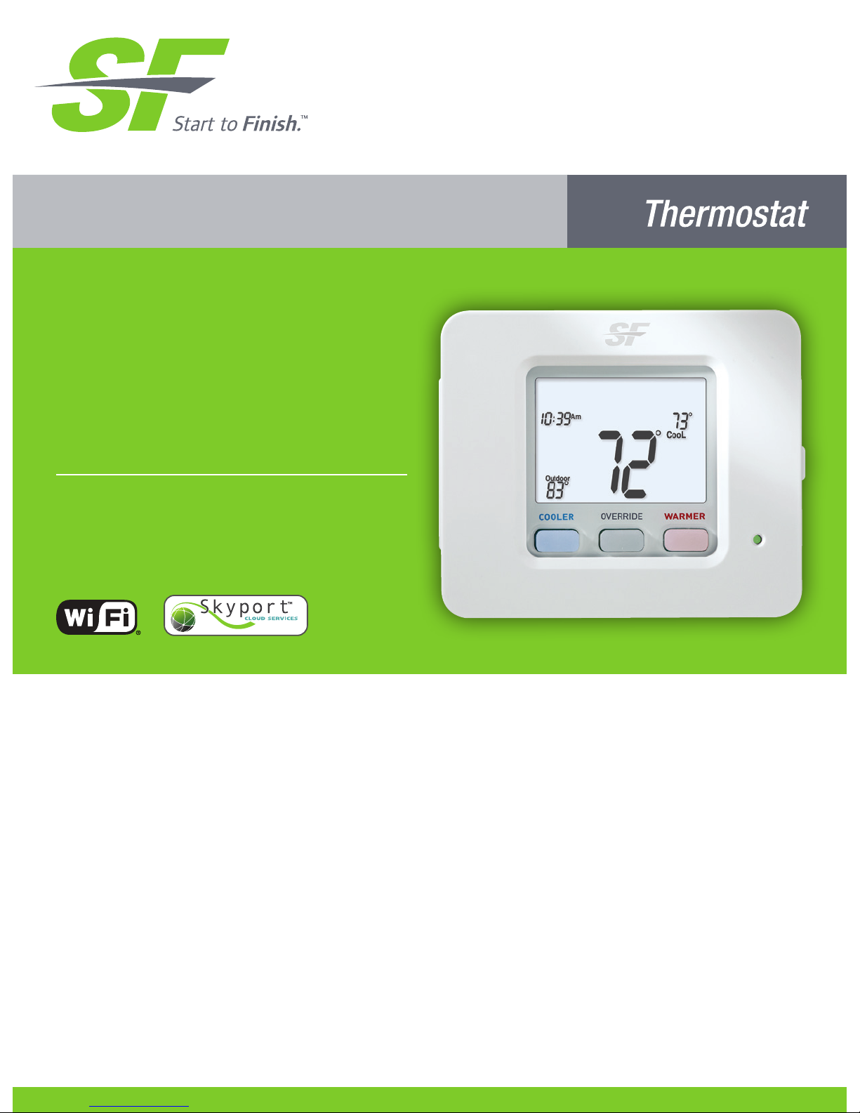
Premier Series
Digital
Thermostat
Non-Programmable
with Humidity Control
Owner’s Manual
and Installation
Instructions
COMMERCIAL
model SFTHCPH022WFC
i
Follow the Installation Instructions before proceeding. Set the
thermostat mode to “OFF” prior to changing settings in setup
or restoring Factory Defaults.
CAUTION
This thermostat has the ability to receive updates to its firmware. Periodically
firmware updates are released by the manufacturer to add features and/or
performance enhancements. This manual was produced reflecting the most
current firmware/feature set at the time of publication, firmware rev. 12. Firmware
releases after rev. 12 may not be adequately depicted in this manual. Please
refer to the appropriate website or contact your place of purchase to learn about
changes to the thermostat after firmware release 12.

ii
Glossary of Terms
Auto-Changeover: A mode in which the thermostat will turn on the
heating or cooling based on room temperature demand.
Cool Setpoint: The warmest temperature that the space should rise
to before cooling is turned on (without regard to deadband).
Deadband: The number of degrees the thermostat will wait, once a
setpoint has been reached, before energizing heating or cooling.
Dehumidify: To reduce the amount of moisture in the air.
Dierential: The forced temperature dierence between the heat
setpoint and the cool setpoint.
Heat Setpoint: The coolest temperature that the space should drop
to before heating is turned on (without regard to deadband).
Humidify: To increase the amount of moisture in the air.
Icon: The word or symbol that appears on the thermostat display.
Mode: The current operating condition of the thermostat (i.e. O,
Heat, Cool, Auto).
Non-Programmable Thermostat: A thermostat that does not have
the capability of running Time Period Programming.
Programmable Thermostat: A thermostat that has the capability of
running Time Period Programming.
Reheat: Running the cooling and 2nd stage strip heaters at the same
time in order to dehumidify the air without signicantly cooling down
the room temperature.
Temperature Swing: Same as Deadband.
Time Period Programming: A program that allows the thermostat to
automatically adjust the heat setpoint and/or the cool setpoint based
on the time of the day.

iii
Table of Contents
GET TO KNOW YOUR THERMOSTAT
Get to Know Your Thermostat ....................................................... 1
Quick Start ..................................................................................... 6
INTALLATION INSTRUCTIONS ....................................................... 9
Sample Wiring Diagrams .............................................................. 13
Test Operation ............................................................................... 16
USER SETUP
Backlight Operation ...................................................................... 17
Scrolling Display Options ............................................................. 18
Thermostat Display Options......................................................... 18
Emergency Heat ........................................................................... 18
RF Module ..................................................................................... 19
Wi-Fi Module ................................................................................. 20
System Runtimes .......................................................................... 21
INSTALLER SETUP
Program Mode Operation ............................................................. 23
Programming Fan Operation ........................................................ 25
Humidication & Dehumidication .............................................. 26
Dry Contact Operation ................................................................. 27
Remote Sensor Operation ............................................................ 27
ADR ............................................................................................... 29
Locking/Unlocking the Keypad .................................................... 34
Factory Defaults............................................................................ 35
TECHNICIAN SETUP
Sensor Calibration ........................................................................ 36
Equipment Testing ........................................................................ 36
Advanced Output Testing ............................................................. 36
Troubleshooting ............................................................................ 37
Advanced Setup Table ................................................................. 38
WARRANTY ..................................................................................... 40
TECHNICAL SPECIFICATIONS ...................................................... 41
1
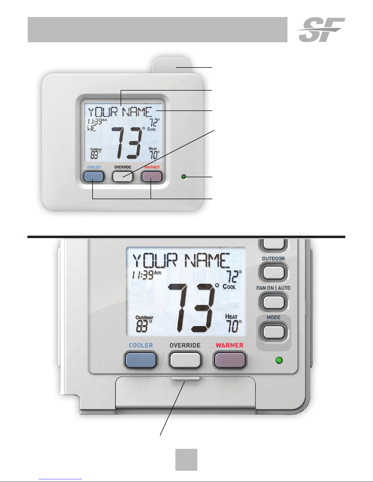
Get To Know Your Thermostat
Optional WiFi Module
Backlit, Scrolling Display
Backlit LCD Display
Heat or Cool
Demand Indicator
Red = Heat, Green = Cool
Backlit Cooler & Warmer
Buttons
Setup Buttons Behind Door
Override Button
2
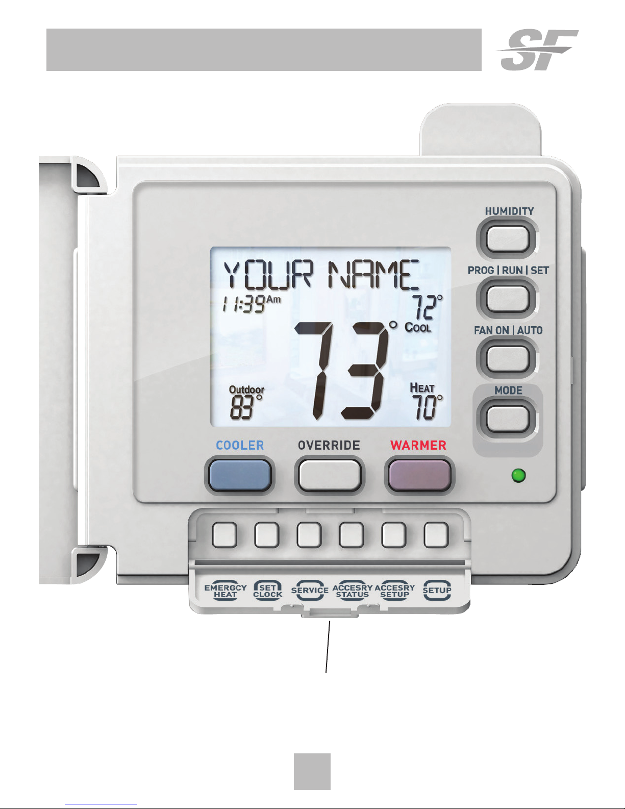
Get To Know Your Thermostat
Setup Buttons
3
Get To Know Your Thermostat
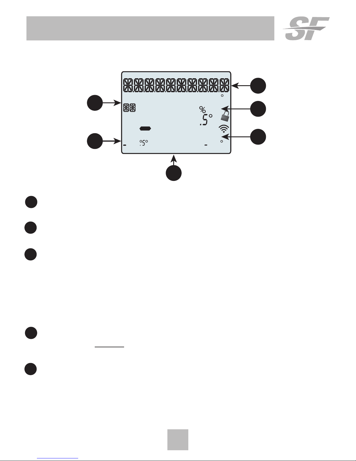
Display Features
HI
Lo
Outdoor
Fan On
COOL
AUXHEAT
Override
Day Night
Morning
Evening
Setup Step
2nd
Stage
Am
Pm
18:88
188
188
88
188
1
3
3
4
5
2
1 The scrolling display will be used to help you easily navigate
the setup screens in the thermostat.
2 Clock
Indicates the current time.
3 Mode Indicators
Selects the operational mode of the equipment.
HEAT - Indicates the heating mode.
COOL - Indicates the air conditioning mode.
HEAT & COOL - Indicates the system will automatically change-over
between heat and cool modes as the temperature varies.
OFF - Indicates heating and cooling is turned off.
4 Room Temperature Display
Indicates the current room temperature and displays the outdoor
temperature when selected.
5 Outdoor icon
Indicates the temperature displayed is from the optional
outdoor sensor.
4
Get To Know Your Thermostat
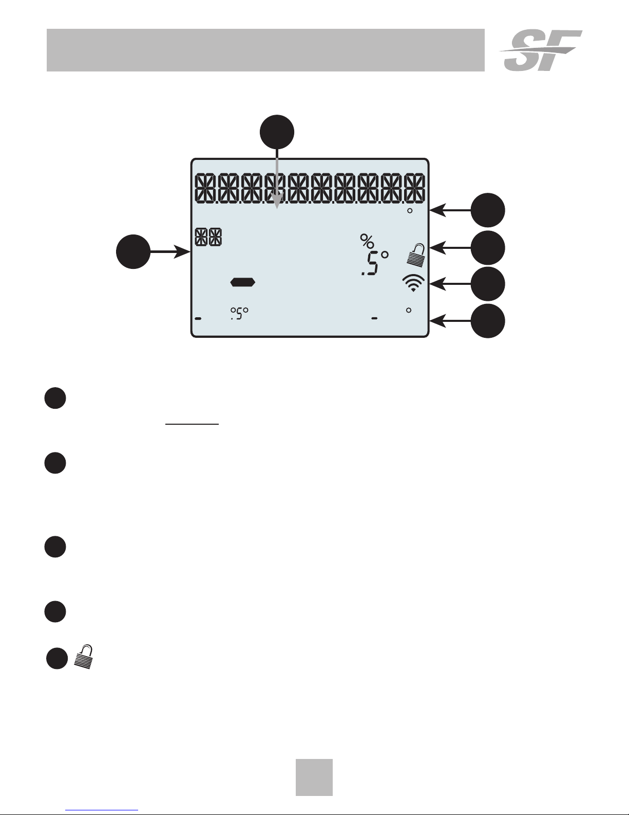
Display Features
Outdoor
Fan On
COOL
AUXH
EAT
Override
Day Night
Morning
Evening
Setup Step
2nd
Stage
Am
Pm
18:88
188
188
88
188
10
6
6
7
8
9
6 Desired Set Temperature
Indicates desired room temperature(s). Also displays
the highest and lowest temperatures for the day.
7 Wi-Fi icons
One dot indicates the thermostat recognizes the wireless module.
The full icon indicates the thermostat is currently connected to
the Local access point, via the optional Wi-Fi Module.
8 Setup Step icon
Indicates the step number when the thermostat
is in the setup mode.
9 2nd Stage icon
Indicates what stage of cooling or heating is currently energized.
10 icon
Indicates the keypad has been locked.
5
Get To Know Your Thermostat
HI
Lo
Outdoor
Fan On
COOL
AUXH
EAT
Override
Day Night
Morning
Evening
Setup Step
2nd
Stage
Am
Pm
18:88
188
188
88
188
11
12
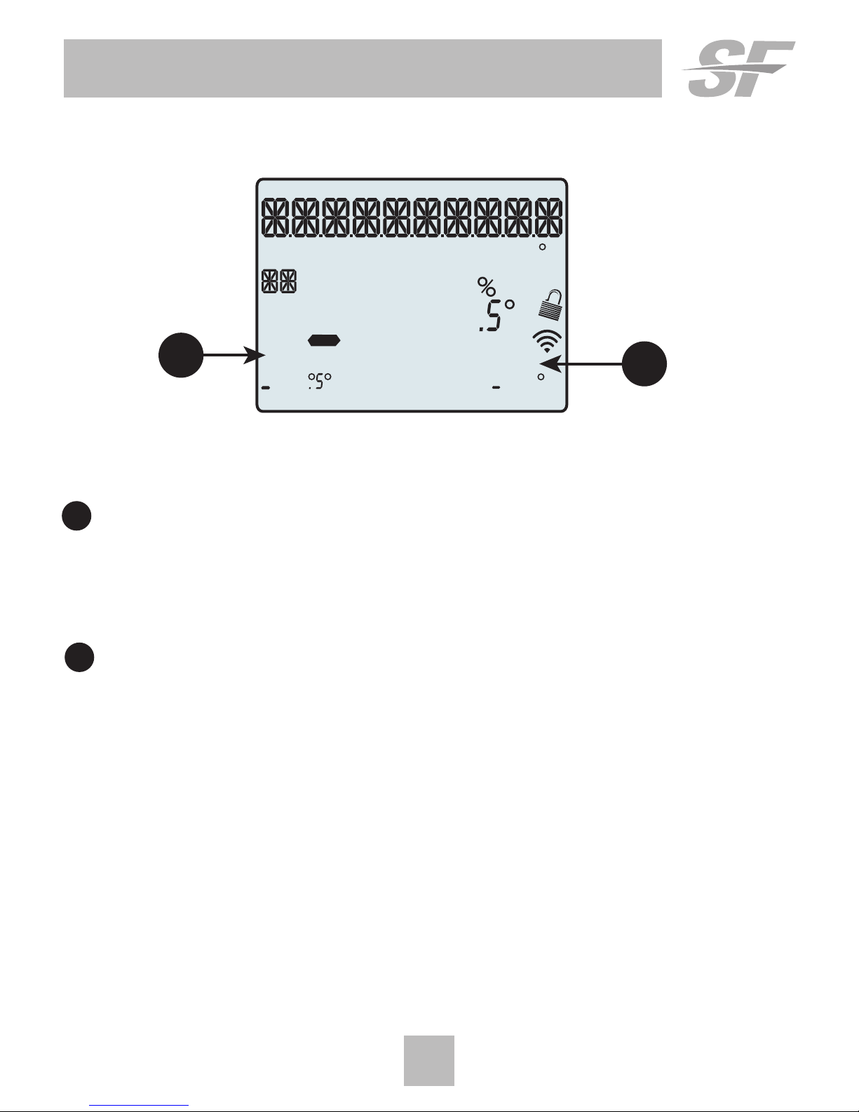
Display Features
11 AuxHeat icon
Indicates 2nd stage electric strip heat is being used when the
thermostat is programmed for Heat Pump operation. Only the
Aux icon will appear during Cool to Dehumidify to indicate
Reheat operation.
12 Fan On icon
Indicates constant, continuous fan operation.
When Fan On is not lit - indicates the fan will only
operate when necessary to heat or to cool.
6
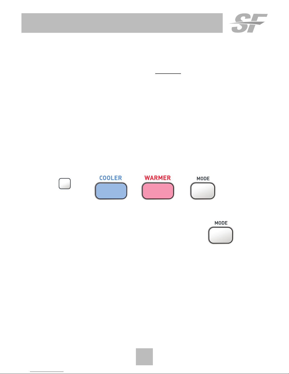
Quick Start
During Setup and Programming:
Press the WARMER or COOLER buttons to modify the selection.
Press the MODE button to advance and confirm through the setup steps.
Setting the Clock
Not available when wi-fi module is present
Press the SET CLOCK button. Adjust the clock using the WARMER or
COOLER buttons. Press MODE to advance to the day setting. Adjust the
day using the WARMER or COOLER buttons. Press the SET CLOCK
button to confirm settings.
NOTE: To adjust the time by hours, press and hold the FAN button
while pressing the WARMER or COOLER buttons.
Selecting the Heat or Cool Mode
Select mode by pressing the MODE button.
Heating Only - Only the heating operation will be controlled by the
thermostat in this mode.
Cooling Only - Only the cooling operation will be controlled by the
thermostat in this mode.
Heating or Cooling (Auto-Changeover) - AUTO will automatically select
heat or cool based on room temperature demand.
OFF - OFF indicates both heating and air conditioning systems are turned off.
Set
Clock
7
Quick Start
Selecting your desired temperature
AUTO-CHANGEOVER MODE - Pressing the WARMER or COOLER
buttons in Auto mode will adjust both the heat and cool setpoints
simultaneously. To adjust heat and cool setpoints individually, choose
HEAT mode to adjust the heat setpoint and COOL mode to adjust the
cool setpoint, then return to AUTO mode.
HEAT OR COOL MODE - Pressing the WARMER or COOLER buttons
in Heat or Cool mode will adjust only the heat or cool setpoints
individually displayed.
Using the Fan Button
Fan On indicates constant fan operation. Fan On is not allowed
when the thermostat is in the OFF mode. Pressing the FAN button
toggles this feature. If you don’t see “Fan On”, the fan is in auto mode
and will only turn on during a heat or cool demand.
Using the Override Button
Unoccupied Operation —During
programmed, unoccupied
periods, pressing the OVERRIDE button will force the thermostat into Occupied
1 setting for 30 minutes. Each press of the OVERRIDE button will add another
30 minutes of time for up to 4 hours. If the maximum time has been set,
the next press of the OVERRIDE button will reset the timer and return the
thermostat to the correct time period program for the day
Occupied Operation—During programmed, occupied periods, pressing the
OVERRIDE button will force the thermostat into an unoccupied period for the
rest of the day. During this forced unoccupied period, the OVERRIDE button
will operate as described above.
To adjust the setpoints for the Unoccupied mode, see page 29.
Current Override Hours (Setup step 10) - This counter keeps track of the
number of hours that the thermostat is overridden into Occupied settings.
Press FAN to reset.
NOTE: Override may only be
used when the thermostat is
set to PROGRAM ON.

Viewing the Temperature Sensors
OUTDOOR TEMP - Press the OUTDOOR button to view the current
outdoor temperature. If connected to a Skyport account, pressing
outdoor button will show the temperatures for your location if you
don’t have a wired sensor connected.
Press the OUTDOOR button again to view any connected wired sensor
(Remote or Supply).
Note: If no outdoor sensor is connected, and there isn’t outdoor temperature via
Wi-Fi, then 2 dashes [- -] will appear with the first button press.
REMOTE/SUPPLY TEMP - Press the Accessory Status button to
view linked wireless and wired sensors and other accessories.
Press the Accessory Status button to return to the main screen.
Setup step #26 selects the use of the wired temperature sensor.
Viewing the Indoor Humidity Sensor
IMPORTANT: Allow at least 2 minutes after the thermostat is
powered on for the humidity to read correctly.
Press the HUMIDITY button then the mode button to display the current
humidity measured at the thermostat. The room’s relative humidity is displayed
in the top left corner. The humidification setpoint appears in the larger, center
display and can be adjusted using the WARMER or COOLER buttons. Press the
MODE button again to view and adjust the dehumidification setpoints. Press
the HUMIDITY or MODE button again to confirm settings and return to normal
operation.
Note: Due to variations in environmental and equipment conditions, it is not
always possible to achieve the desired humidification or dehumidification
setpoint.
8
Quick Start
ACCESRY
STATUS
OUTDOOR

9
Installation Instructions
Remove and Replace the old thermostat
To install the thermostat properly, please follow these step by step
instructions. If you are unsure about any of these steps, call a qualified
technician for assistance.
• Assemble tools: Flat blade screwdriver, wire cutters and wire
strippers.
• Make sure your Heater/Air Conditioner is working properly
before beginning installation of the thermostat.
• Carefully unpack the thermostat. Save the screws, any brackets,
and instructions.
• Turn off the power to the Heating/Air Conditioning system at
the main fuse panel. Most residential systems have a separate
breaker for disconnecting power to the furnace.
• Remove the cover of the old thermostat. If it does not come off
easily, check for screws.
• Loosen the screws holding the thermostat base or subbase to
the wall and lift away.
• If you have a smart phone handy, take a photo of the wiring for
future reference.
• Disconnect the wires from the old thermostat. Tape the ends of
the wires as you disconnect them, and mark them with the letter
of the terminal for easy reconnection to the new thermostat.
• Keep the old thermostat for reference purposes, until your new
thermostat is functioning properly.
10
Installation Instructions
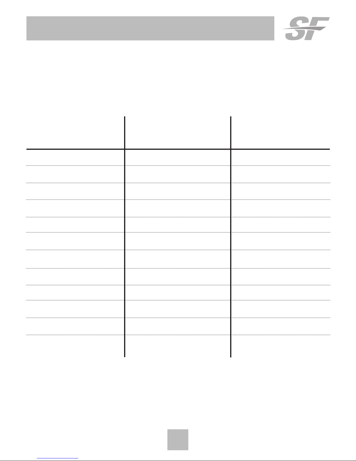
Wire Connections
If the terminal designations on your old thermostat do not match those
on the new thermostat, refer to the chart below or the wiring
diagrams that follow.
Wire from the Install on the
old thermostat Function new thermostat
terminal marked connector marked
G or F Fan G
Y1, Y Cooling Y1
W1, W Heating W1/0/B
Rh, R, M, Vr, A Power R
C Common C
O/B Rev. Valve W1/O/B*
W2 2nd Stage Heat W2
Y2 2nd Stage Cooling Y2
H, Hum Humidity HUM
D, Dehum Dehumidity DEHUM
Ck1 Dry Contact Switch DRY CONTACT
CKGND Dry Contact Switch DRY CONTACT
* O/B is used if your system is a Heat Pump.
 Loading...