


Configuration Guide
SEYPOS-DT6800
Hand Free Area Image Scanner
V1.3

Table of Contents
Chapter 1 General Description .............................................. 1
Chapter 2 Introduction .......................................................... 2
Chapter 3 User Preferences ................................................... 4
RETURN TO DEFAULT ................................................................................ 4
PARAMETER SCANNING ........................................................................... 5
BEEPER TONE .............................................................................................. 6
BEEPER VOLUME ........................................................................................ 7
BEEPER DURATION .................................................................................... 7
TRIGGER MODES ........................................................................................ 8
POWER MODE .............................................................................................. 9
Mobile Phone/Display Mode ................................................................. 9
Chapter 4 Serial Interface ...................................................
SERIAL PARAMETER DEFAULTS .......................................................... 11
SERIAL HOST TYPES ................................................................................ 12
BAUD RATE ................................................................................................. 13
PARITY .......................................................................................................... 14
STOP BIT SELECT...................................................................................... 15
DATA BITS .................................................................................................... 15
10

- II -
CHECK RECEIVE ERRORS ...................................................................... 16
HARDWARE HANDSHAKING ................................................................... 17
SOFTWARE HANDSHAKING ................................................................... 19
HOST SERIAL RESPONSE TIME-OUT .................................................. 21
RTS LINE STATE ........................................................................................ 22
INTERCHARACTER DELAY ..................................................................... 23
Chapter 5 USB Interface ......................................................
USB HOST PARAMETERS ....................................................................... 31
USB COUNTRY KEYBOARD TYPES (COUNTRY CODES) ............... 33
USB KEYSTROKE DELAY ........................................................................ 35
USB CAPS LOCK OVERRIDE .................................................................. 35
USB IGNORE UNKNOWN CHARACTERS ............................................. 36
EMULATE KEYPAD .................................................................................... 36
USB KEYBOARD FN 1 SUBSTITUTION ................................................. 37
FUNCTION KEY MAPPING ....................................................................... 37
SIMULATED CAPS LOCK .......................................................................... 38
CONVERT CASE ......................................................................................... 38
ASCII CHARACTER SET FOR USB ........................................................ 39
30

- III -
Chapter 6 Symbologies .......................................................
SYMBOLOGY PARAMETER DEFAULTS ............................................... 51
UPC/EAN ....................................................................................................... 56
CODE 128 ..................................................................................................... 67
CODE 39 ....................................................................................................... 69
CODE 93 ....................................................................................................... 77
CODE 11 ....................................................................................................... 79
INTERLEAVED 2 OF 5 (ITF) .................................................................... 82
DISCRETE 2 OF 5 (DTF) ......................................................................... 86
50
CODABAR (NW-7) ..................................................................................... 88
MSI ............................................................................................................... 91
POSTAL CODES ....................................................................................... 95
GS1 DATABAR .......................................................................................... 99
COMPOSITE .............................................................................................. 104
2D SYMBOLOGIES ................................................................................... 109
PDF417 ........................................................................................................ 109
MICROPDF417 .......................................................................................... 109
DATA MATRIX............................................................................................ 111
MAXICODE ................................................................................................. 111
QR CODE .................................................................................................... 112
REDUNDANCY LEVEL ............................................................................. 113
SECURITY LEVEL ..................................................................................... 114
INTERCHARACTER GAP SIZE .............................................................. 115
MACRO PDF FEATURES ........................................................................ 116
AZTEC
.................................................................................................... 112
................................
Han Xin
.................................................................................................... 112
................................

- IV -
Chapter 7 Miscellaneous Scanner Options ........................
TRANSMIT CODE ID CHARACTER ...................................................... 122
PREFIX/SUFFIX VALUES ........................................................................ 123
SCAN DATA TRANSMISSION FORMAT .............................................. 124
FN1 SUBSTITUTION VALUES ................................................................ 125
120
APPENDIX A: STANDARD DEFAULT PARAMETERS ...................... 126
APPENDIX B: DEFAULT CODE IDENTIFIERS ................................... 134
APPENDIX C: ASCII CHARACTER SET ......................................... 141
APPENDIX D: NUMERIC BAR CODES........................................... 154
APPENDIX E: READABLE SYMBOLOGIES ................................... 156

1
Chapter 1 General Description
Thank you for purchasing this barcode scanner with an advanced and versatile
decoder. The decoder works with variety of barcode types, reading devices, and
computer interfaces. It discriminates over twenty different symbologies automatically.
This menu provides an easy way to configure the decoding options and interface
selections by scanning bar codes listed in the menu.
FCC Approval
This device had been tested in accordance with the procedures and in compliance with Part 15
Subpart B of FCC Rules and keeps all requirements, according ANSI C63.4 & FCC Part 15 B
Regulation and CISPR22 Class B.
CE Standards
The CE mark as shown here indicates this produc t had been tested in accordance with the
procedures given in European Council Directive 2004/108/EC and confirmed to comply with the
Europe Standard EN55022:2006:Class B, EN 55024:1998+A1:2001+A2:2003,IEC61000-32:2006,IEC61000-3-3:1995+A1:2005,IEC61000-4-2:2001,IEC61000-4-:2006,IEC610004-4:2004,IEC61000-4-5: 2006,IEC61000-4-6:2001,IEC61000-4-8:2001,IEC61000-4-11:2004.
LEGISLATION AND WEEE SYMBOL
This marking shown on the product or its literature, indicates that it should not be
disposed with other households wastes at the end of its working life. To prevent
possible harm to the environment or human health from uncontrolled waste
disposal, please separate this from other types of wastes and recycle it responsibly to
promote the sustainable re-use of material resources. Household users should
contact either the retailer where they purchased this product, or their local
government office, for details of where and how they can take this item for
environmentally safe recycling. Business users should contact their supplier and
check the terms and conditions of the purchase.

2
Chapter 2 Introduction
This document provide an easy way to program the decoding options and
interface selections by scanning bar codes listed in this guide.
Important Notice
1. This document is in A5 size. Please check your printing setting before
printing it out.
2. When printing barcodes for programming, the use of a high-resolution
laser printer is strongly suggested for the best scan result.
3. The settings shall be updated periodically without prior notice. For the
latest version, please contact your authorized distributor.
Factory Default Setting
The factory default settings are shown with < > and bold in the following
sections. You can make your own settings by scan a series of selected
barcode patches in this manual to affect setup and programming of your
handheld 2D Image Reader.
By scanning “Set All Defaults” Label, the settings will go back to the factory
default settings.
Settings and Programming
Scan a series of selected barcode patches in this manual to affect setup and
programming of your handheld 2D Image Reader. Decoding options and
interface protocols can be tailored to a specific application.
Setup parameters are stored in non-volatile memory in the scanner and are
retained even when power is off. Setup parameters change only when you
reset them.
You may need to hide adjacent code patches with your hand when doing
programming scanning.

3
Default Factory Device Settings
User Preferences
Parameter Default
Set Default Parameter All Defaults
Parameter Scanning Enable
Beeper Tone
Beeper Volume High
Beeper Duration Long
Trigger Mode
Handheld/Hands-free Scanner Level
Scan Module Presentation
Power Mode
Handheld/Hands-free Scanner Low Power
Scan Module Low Power
Time Delay to Low Power Mode 1.0 Sec
Decode Session Timeout 9.9 Sec
Timeout Between Decodes, Same Symbol 0.4 Sec
Beep After Good Decode Enable
Presentation Mode Session Timeout 2 Seconds
High

4
Chapter 3 User Preference
RETURN TO DEFAULT ( HID Keyboard Emulation )
Report Version
Scan the bar code below to report the version of software currently installed in
the decoder.
Report Software Version

5
PARAMETER SCANNING
To disable decoding of parameter bar codes, including the Set All Defaults
parameter bar code, scan the Disable Parameter Scanning bar code below. To
enable decoding of parameter bar codes, scan Enable Parameter Scanning.
< Enable Parameter Scanning >
Disable Parameter Scanning

6
BEEPER TONE
To select a decode beep frequency (tone); scan the Low Frequency, Medium
Frequency, or High Frequency bar code.
Low Frequency
Medium Frequency
< High Frequency >

7
BEEPER VOLUME
To select a beeper volume, scan the Low Volume, Medium Volume, or High
Volume bar code.
Low Volume
Medium Volume
< High Volume >
BEEPER DURATION
To select the duration for the beeper, scan one of the following bar codes.
Short
Medium
< Long >

8
TRIGGER MODES
Presentation Mode - When the device detects an object in its field
of view it triggers and attempts to decode. The range of object
detection does not vary under normal lighting conditions. This
applies to decode mode only. In this mode the unit does not enter
its sleep state.
< Presentation Mode >

9
POWER MODE
This parameter determines whether or not power remains on after a decode
attempt. In low power mode, the decoder enters into a low power consumption
mode to preserve battery life after each decode attempt. In continuous power
mode, power remains on after each decode attempt.
Continuous On
< Low Power Mode >
Mobile Phone/Display Mode
This mode improves bar code reading performance with target bar codes
dispalyed on mobile phones and electronic displays.
*
Disable Mobile Phone/Display Mode
(00h)
Enable Mobile Phone/Display Mode
(03h)

10
Chapter 4 Serial Interface
Introduction
This chapter describes how to set up the decoder with a serial host. The serial
interface is used to connect the decoder to point-of sale devices, host
computers, or other devices with an available serial port (e.g. com port).
Note: The decoder uses TTL signal levels, which interface with most system
architectures. System architectures that use RS-232C signal levels require a
conversion circuitry.
The serial host type requires proper configuration of the sysconfig lines, and
typically require scanning bar code menus as part of initial configuration.
Most computer monitors allow scanning the bar codes directly on the screen.
When scanning from the screen is sure to set the document magnification to a
level where the bar code can be seen clearly, and bars and/or spaces are not
merging.

11
SERIAL PARAMETER DEFAULTS
The table below lists the defaults for serial host parameters. To change any
option, scan the appropriate bar code(s) provided in the Serial Host
Parameters section.
Note: See Appendix A, Standard Default Parameters for all user preferences,
hosts, symbologies, and miscellaneous default parameters.
Serial Host Default Table
Serial Host Parameters
Parameter Default
Serial Host Types Standard
Baud Rate 9600
Parity Type None
Stop Bit Select 1 Stop Bit
Data Bits 8-Bit
Check Receive Errors Enable
Hardware Handshaking None
Software Handshaking None
Host Serial Response Time-out 2 Sec
RTS Line State Low RTS
Beep on <BEL> Disable
Intercharacter Delay 0 msec
Nixdorf Beep/LED Options
Normal
Operation
Ignore Unknown Characters
Send Bar
Code

12
SERIAL HOST TYPES
To select a serial host interface, scan one of the following bar codes.
Enable Serial Host (Standard RS232)
*Scanning Enable Serial Host (No Variant) activates the serial driver, but does
not change port settings (e.g., parity, data bits, handshaking). Selecting
another serial host type bar code changes these settings.
OPOS/JPOS

13
BAUD RATE
Baud rate is the number of bits of data transmitted per second. Set the
decoder's baud rate to match the baud rate setting of the host device.
Otherwise, data may not reach the host device or may reach it in distorted
form.
< Baud Rate 9600>
Baud Rate 38,400
Baud Rate 57,600
Baud Rate 115,200

14
PARITY
A parity check bit is the most significant bit of each ASCII coded character.
Select the parity type according to host device requirements.
Select Odd parity and the parity bit value is set to 0 or 1, based on data, to
ensure that an odd number of 1 bits are contained in the coded character.
Select Even parity and the parity bit value is set to 0 or 1, based on data, to
ensure that an even number of 1 bits are contained in the coded character.
Select None when no parity bit is required.
Odd
Even
< None >

15
STOP BIT SELECT
The stop bit(s) at the end of each transmitted character marks the end of
transmission of one character and prepares the receiving device for the next
character in the serial data stream. The number of stop bits selected (one or
two) depends on the number the receiving terminal is programmed to
accommodate. Set the number of stop bits to match host device requirements.
< 1 Stop Bit >
2 Stop Bits
DATA BITS
This parameter allows the decoder to interface with devices requiring a 7-bit or
8-bit ASCII protocol.
7-Bit
< 8-Bit >

16
CHECK RECEIVE ERRORS
Select whether or not the parity, framing, and overrun of received characters
are checked. The parity value of received characters is verified against the
parity parameter selected above.
< Check For Received Errors >
Do Not Check For Received Errors

17
HARDWARE HANDSHAKING
The data interface consists of a serial port designed to operate either with or
without the hardware handshaking lines, Request to Send (RTS), and Clear to
Send (CTS).
If Standard RTS/CTS handshaking is not selected, scan data is transmitted as
it becomes available. If Standard RTS/CTS handshaking is selected, scan data
is transmitted according to the following sequence:
The decoder reads the CTS line for activity. If CTS is asserted, the
decoder waits up to Host Serial Response Time-out for the host to
de-assert the CTS line. If, after Host Serial Response Time-out
(default), the CTS line is still asserted, the decoder sounds a
transmit error, and any scanned data is lost.
When the CTS line is de-asserted, the decoder asserts the RTS
line and waits up to Host Serial Response Time-out for the host to
assert CTS. When the host asserts CTS, data is transmitted. If,
after Host Serial Response Time-out (default), the CTS line is not
asserted, the decoder sounds a transmit error, and discards the
data.
When data transmission is complete, the decoder de-asserts RTS
10 msec after sending the last character.
The host should respond by negating CTS. The decoder checks for
a de-asserted CTS upon the next transmission of data.
During the transmission of data, the CTS line should be asserted. If CTS is
deasserted for more than 50 ms between characters, the transmission is
aborted, the decoder sounds a transmission error, and the data is discarded. If
the above communication sequence fails, the decoder issues an error
indication. In this case, the data is lost and must be rescanned. If Hardware
Handshaking and Software Handshaking are both enabled, Hardware
Handshaking takes precedence.
Note: The DTR signal is jumpered to the active state.
None: Scan the bar code below if no Hardware Handshaking is
desired.
Standard RTS/CTS: Scan the bar code below to select Standard
RTS/CTS Hardware Handshaking.
RTS/CTS Option 1: When RTS/CTS Option 1 is selected, the
decoder asserts RTS before transmitting and ignores the state of
CTS. The decoder de-asserts RTS when the transmission is
complete.
RTS/CTS Option 2: When Option 2 is selected, RTS is always high
or low (user-programmed logic level). However, the decoder waits
for CTS to be asserted before transmitting data. If CTS is not
asserted within Host Serial Response Time-out (default), the

18
decoder issues an error indication and discards the data.
RTS/CTS Option 3: When Option 3 is selected, the decoder asserts
RTS prior to any data transmission, regardless of the state of CTS.
The decoder waits up to Host Serial Response Time-out (default)
for CTS to be asserted. If CTS is not asserted during this time, the
decoder issues an error indication and discards the data. The
decoder de-asserts RTS when transmission is complete.
< None >
Standard RTS/CTS
RTS/CTS Option 1
RTS/CTS Option 2
RTS/CTS Option 3

19
SOFTWARE HANDSHAKING
This parameter offers control of the data transmission process in addition to, or
instead of, that offered by hardware handshaking. There are five options.
If Software Handshaking and Hardware Handshaking are both enabled,
Hardware Handshaking takes precedence.
None: When this option is selected, data is transmitted immediately.
No response is expected from host.
ACK/NAK: When this option is selected, after transmitting data, the
decoder expects either an ACK or NAK response from the host.
When a NAK is received, the decoder transmits the same data
again and waits for either an ACK or NAK. After three unsuccessful
attempts to send data when NAKs are received, the decoder issues
an error indication and discards the data.
The decoder waits up to the programmable Host Serial Response
Time-out to receive an ACK or NAK. If the decoder does not get a
response in this time, it issues an error indication and discards the
data. There are no retries when a time-out occurs.
ENQ: When this option is selected, the decoder waits for an ENQ
character from the host before transmitting data. If an ENQ is not
received within the Host Serial Response Time-out, the decoder
issues an error indication and discards the data. The host must
transmit an ENQ character at least every Host Serial Response
Time-out to prevent transmission errors.
ACK/NAK with ENQ: This combines the two previous options. For
re-transmissions of data, due to a NAK from the host, an additional
ENQ is not required.
• XON/XOFF: An XOFF character turns the decoder
transmission off until the decoder receives an XON character.
There are two situations for XON/XOFF:
XOFF is received before the decoder has data to send. When the
decoder has data to send, it waits up to Host Serial Response
Time-out for an XON character before transmission. If the XON is
not received within this time, the decoder issues an error indication
and discards the data.
XOFF is received during a transmission. Data transmission then
stops after sending the current byte. When the decoder receives an
XON character, it sends the rest of the data message. The decoder
waits indefinitely for the XON.

20
< None >
ACK/NAK
ENQ
ACK/NAK with ENQ
XON/XOFF

21
HOST SERIAL RESPONSE TIME-OUT
This parameter specifies how long the decoder waits for an ACK, NAK, or CTS
before determining that a transmission error has occurred. This only applies
when in one of the ACK/NAK Software Handshaking modes, or RTS/CTS
Hardware Handshaking option.
< Minimum
: 2
Sec >
Low: 2.5 Sec
Medium: 5 Sec
High: 7.5 Sec
Maximum: 9.9 Sec

22
RTS LINE STATE
This parameter sets the idle state of the Serial Host RTS line. Scan a bar code
below to select Low RTS or High RTS line state.
< Host
:
Low RTS >
Host: High RTS
BEEP ON <BEL>
When this parameter is enabled, the decoder issues a beep when a <BEL>
character is detected on the serial line. <BEL> is issued to gain a user's
attention to an illegal entry or other important event.
Beep On <BEL> Character
(Enable)
< Do Not Beep On <BEL> Character >
(Disable)
Note: A NULL character must be sent to the decoder before BEL to ensure the
BEL character is processed correctly.

23
INTERCHARACTER DELAY
This parameter specifies the intercharacter delay inserted between character
transmissions.
< Minimum
: 0 msec
>
Low: 25 msec
Medium: 50 msec
High: 75 msec
Maximum: 99 msec

24
IGNORE UNKNOWN CHARACTERS
Unknown characters are characters the host does not recognize. When Send
Bar Codes with Unknown Characters is selected, all bar code data is sent
except for unknown characters, and no error beeps sound on the decoder.
When Do Not Send Bar Codes With Unknown Characters is selected, bar code
data is sent up to the first unknown character and then an error beep will sound
on the decoder.
characters) >
Do Not Send Bar Codes (with
unknown characters)

25
ASCII CHARACTER SET FOR SERIAL HOSTS
The values in the table below can be assigned as prefixes or suffixes for
ASCII character data transmission.
Prefix/Suffix Values
Prefix/Suffix
Value
Full ASCII Code 39
Encode Character
ASCII Character
1000 %U NUL
1001 $A SOH
1002 $B STX
1003 $C ETX
1004 $D EOT
1005 $E ENQ
1006 $F ACK
1007 $G BELL
1008 $H BCKSPC
1009 $I HORIZ TAB
1010 $J LF/NW LN
1011 $K VT
1012 $L FF
1013 $M CR/ENTER
1014 $N SO
1015 $O SI
1016 $P DLE
1017 $Q DC1/XON
1018 $R DC2
1019 $S DC3/XOFF
1020 $T DC4

26
1021 $U NAK
1022 $V SYN
1023 $W ETB
1024 $X CAN
1025 $Y EM
1026 $Z SUB
1027 %A ESC
1028 %B FS
1029 %C GS
1030 %D RS
1031 %E US
1032 Space Space
1033 /A !
1034 /B "
1035 /C #
1036 /D $
1037 /E %
1038 /F &
1039 /G ‘
1040 /H (
1041 /I )
1042 /J *
1043 /K +
1044 /L ,
1045 - 1046 . .
1047 /O /
1048 0 0
1049 1 1

27
1050 2 2
1051 3 3
1052 4 4
1053 5 5
1054 6 6
1055 7 7
1056 8 8
1057 9 9
1058 /Z :
1059 %F ;
1060 %G <
1061 %H =
1062 %I >
1063 %J ?
1064 %V @
1065 A A
1066 B B
1067 C C
1068 D D
1069 E E
1070 F F
1071 G G
1072 H H
1073 I I
1074 J J
1075 K K
1076 L L
1077 M M
1078 N N

28
1079 O O
1080 P P
1081 Q Q
1082 R R
1083 S S
1084 T T
1085 U U
1086 V V
1087 W W
1088 X X
1089 Y Y
1090 Z Z
1091 %K [
1092 %L \
1093 %M ]
1094 %N ^
1095 %O _
1096 %W `
1097 +A a
1098 +B b
1099 +C c
1100 +D d
1101 +E e
1102 +F f
1103 +G g
1104 +H h
1105 +I i
1106 +J j
1107 +K k

29
1108 +L l
1109 +M m
1110 +N n
1111 +O o
1112 +P p
1113 +Q q
1114 +R r
1115 +S s
1116 +T t
1117 +U u
1118 +V v
1119 +W w
1120 +X x
1121 +Y y
1122 +Z z
1123 %P {
1124 %Q |
1125 %R }
1126 %S ~
1127
Undefined
7013
ENTER

30
Chapter 5 USB Interface
Introduction
This chapter describes how to set up the decoder with a USB host. The
decoder connects directly to a USB host, or a powered USB hub, and is
powered by it. No additional power supply is required.
Note: Most computer monitors allow scanning the bar codes directly on the
screen. When scanning from the screen, be sure to set the document
magnification to a level where the bar code can be seen clearly, and bars
and/or spaces are not merging.
USB Parameter Defaults
Table below lists the defaults for USB host parameters. To change any option,
scan the appropriate barcode(s) provided in the Parameter Descriptions
section.
Note: See Appendix A, Standard Default Parameters for all user preferences,
hosts, symbologies, and miscellaneous default parameters.
USB Host Default Table
USB Host Parameters
Parameters Default
USB Device Type HID Keyboard Emulation
Native API (SNAPI) Status Handshaking
Enable SNAPI Status
Handshaking
USB Country Keyboard Types (Country Codes) North American
USB Keystroke Delay No Delay
USB CAPS Lock Override Disable
USB Ignore Unknown Characters Enable
Emulate Keypad Disable
USB FN1 Substitution Disable
Function Key Mapping Disable
Simulated Caps Lock Disable
Convert Case No Case Conversion

31
USB HOST PARAMETERS
USB Device Type
Select the desired USB device type.
Note: When changing USB Device Types, the decoder automatically resets.
The decoder issues the standard startup beep sequences.
< HID Keyboard Emulation >
USB virtual COM port emulation;
(requiring driver)
32
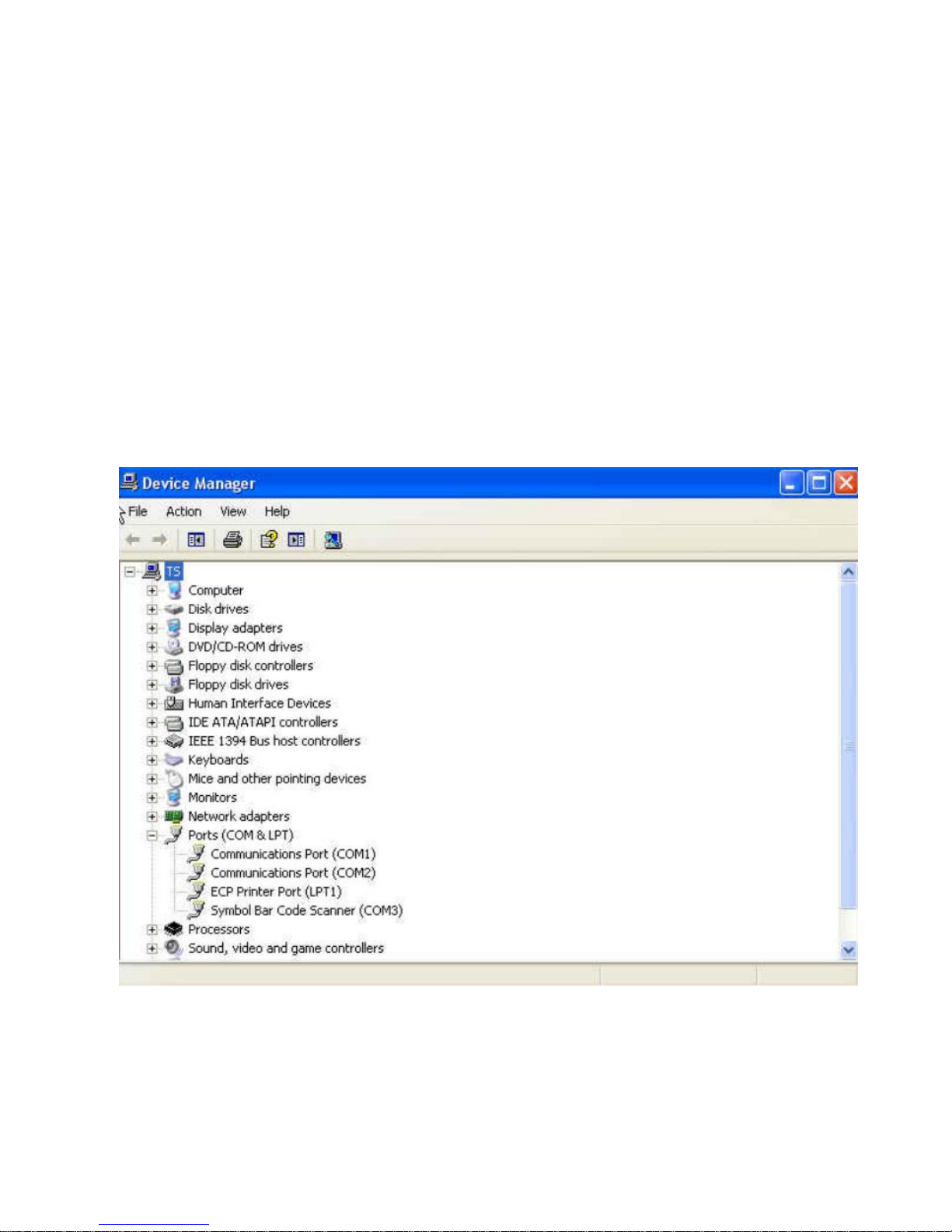
* Note: Steps for activating CDC COM port emulation (USB virtual COM):
1. Execute the driver (installMOTCDC.exe). If you don’t have the driver,
contact your distributor.
2. Connect the scanner USB cable to the host computer. The scanner would
give a “Do Re Mi” melody when powered on.
3. Read the “CDC COM Port Emulation” barcode to set up the interface.
4. On the computer, check Device Manager to see if the computer
successfully detects the scanner as “Bar Code Scanner.” The COM
port number would vary depending on different hardware environment.
5. If you can’t directly install the driver follow the Found New Hardware Wizard
to locate the install the driver.

33
USB COUNTRY KEYBOARD TYPES (COUNTRY CODES)
Scan the bar code corresponding to the keyboard type. This setting applies
only to the USB HID Keyboard Emulation device.
Note: When changing USB country keyboard types the decoder automatically
resets. The decoder issues the standard startup beep sequences.
< North American Standard USB
Keyboard >
German Windows
French Windows

34
French Canadian Windows 2000/XP
French Canadian Windows 95/98
Spanish Windows
Italian Windows
Swedish Window
UK English Windows
Japanese Windows (ASCII)
Portuguese-Brazilian Windows

35
USB KEYSTROKE DELAY
This parameter sets the delay, in milliseconds, between emulated keystrokes.
Scan a bar code below to increase the delay when hosts require a slower
transmission of data.
< No Delay >
Medium Delay (20 msec)
Long Delay (40 msec)
USB CAPS LOCK OVERRIDE
This option applies only to the HID Keyboard Emulation device. When enabled,
the case of the data is preserved regardless of the state of the caps lock key.
This setting is always enabled for the Japanese, Windows (ASCII) keyboard
type and can not be disabled.
Override Caps Lock Key(Enable)
< Do Not
Override Caps Lock Key
>
(Disable)

36
USB IGNORE UNKNOWN CHARACTERS
This option applies only to the HID Keyboard Emulation device and IBM device.
Unknown characters are characters the host does not recognize. When Send
Bar Codes With Unknown Characters is selected, all bar code data is sent
except for unknown characters, and no error beeps sound. When Do Not Send
Bar Codes With Unknown Characters is selected, for IBM devices, bar codes
containing at least one unknown character are not sent to the host, and an
error beep sounds. For HID Keyboard Emulation devices, the bar code
characters up to the unknown character are sent, and an error beep sounds.
< Send Bar Codes with Unknown
Characters (Transmit) >
Do Not Send Bar Codes with
Unknown Characters (Disable)
EMULATE KEYPAD
When enabled, all characters are sent as ASCII sequences over the numeric
keypad. For example ASCII A would be sent as “ALT make” 0 6 5 “ALT Break”.
This allows support for other country variants.
< Disable Keypad Emulation >
Enable Keypad Emulation

37
USB KEYBOARD FN 1 SUBSTITUTION
This option applies only to the USB HID Keyboard Emulation device. When
enabled, this allows replacement of any FN 1 characters in an EAN 128 bar
code with a Key Category and value chosen by the user.
Enable
< Disable >
FUNCTION KEY MAPPING
ASCII values under 32 are normally sent as a control-key sequence. When this
parameter is enabled, the keys in bold are sent in place of the standard key
mapping. Table entries that do not have a bold entry remain the same whether
or not this parameter is enabled.
< Disable Function Key Mapping >
Enable Function Key Mapping

38
SIMULATED CAPS LOCK
When enabled, the decoder inverts upper and lower case characters on the bar
code as if the Caps Lock state is enabled on the keyboard. This inversion is
done regardless of the current state of the keyboard’s Caps Lock state.
< Disable Simulated Caps Lock >
Enable Simulated Caps Lock
CONVERT CASE
When enabled, the decoder converts all bar code data to the selected case.
< No Case Conversion >
Convert All to Upper Case
Convert All to Lower Case

39
ASCII CHARACTER SET FOR USB
USB Prefix/Suffix Values
Prefix/ Suffix
Value
Full ASCII Code
39 Encode
Character
Keystroke
1000 %U CTRL 2
1001 $A CTRL A
1002 $B CTRL B
1003 $C CTRL C
1004 $D CTRL D
1005 $E CTRL E
1006 $F CTRL F
1007 $G CTRL G
1008
$H
CTRL
H/BACKSPACE
1
1009 $I CTRL
I/HORIZONTAL
TAB
1
1010 $J CTRL J
1011 $K CTRL K
1012 $L CTRL L
1013 $M
CTRL M/ENTER
1
1014 $N CTRL N
1015 $O CTRL O
1016 $P CTRL P
1017 $Q CTRL Q
1018 $R CTRL R
1019 $S CTRL S
1020 $T CTRL T
1021 $U CTRL U
1022 $V CTRL V

40
1023 $W CTRL W
1024 $X CTRL X
1025 $Y CTRL Y
1026 $Z CTRL Z
1027 %A
CTRL [/ESC
1
1028 %B CTRL \
1029 %C CTRL ]
1030 %D CTRL 6
1031 %E CTRL
1032 Space Space
1033 /A !
1034 /B “
1035 /C #
1036 /D $
1037 /E %
1038 /F &
1039 /G ‘
1040 /H (
1041 /I )
1042 /J *
1043 /K +
1044 /L ,
1045 - 1046 . .
1047 /O /
1048 0 0
1049 1 1
1050 2 2
1051 3 3

41
1052 4 4
1053 5 5
1054 6 6
1055 7 7
1056 8 8
1057 9 9
1058 /Z :
1059 %F ;
1060 %G <
1061 %H =
1062 %I >
1063 %J ?
1064 %V @
1065 A A
1066 B B
1067 C C
1068 D D
1069 E E
1070 F F
1071 G G
1072 H H
1073 I I
1074 J J
1075 K K
1076 L L
1077 M M
1078 N N
1079 O O
1080 P P

42
1081 Q Q
1082 R R
1083 S S
1084 T T
1085 U U
1086 V V
1087 W W
1088 X X
1089 Y Y
1090 Z Z
1091 %K [
1092 %L \
1093 %M ]
1094 %N ^
1095 %O
_
1096 %W `
1097 +A a
1098 +B b
1099 +C c
1100 +D d
1101 +E e
1102 +F f
1103 +G g
1104 +H h
1105 +I i
1106 +J j
1107 +K k
1108 +L l
1109 +M m

43
1110 +N n
1111 +O o
1112 +P p
1113 +Q q
1114 +R r
1115 +S s
1116 +T t
1117 +U u
1118 +V v
1119 +W w
1120 +X x
1121 +Y y
1122 +Z z
1123 %P {
1124 %Q |
1125 %R }
1126 %S ~
The keystroke in bold is sent only if the “Function Key
Mapping” is enabled. Otherwise, the unbolded keystroke is
sent.

44
USB ALT Key Character Set
ALT Keys Keystroke
2064 ALT 2
2065 ALT A
2066 ALT B
2067 ALT C
2068 ALT D
2069 ALT E
2070 ALT F
2071 ALT G
2072 ALT H
2073 ALT I
2074 ALT J
2075 ALT K
2076 ALT L
2077 ALT M
2078 ALT N
2079 ALT O
2080 ALT P
2081 ALT Q
2082 ALT R
2083 ALT S
2084 ALT T
2085 ALT U
2086 ALT V
2087 ALT W
2088 ALT X
2089 ALT Y
2090 ALT Z

45
USB GUI Key Character Set
GUI Key Keystroke
3000 Right Control Key
3048 GUI 0
3049 GUI 1
3050 GUI 2
3051 GUI 3
3052 GUI 4
3053 GUI 5
3054 GUI 6
3055 GUI 7
3056 GUI 8
3057 GUI 9
3065 GUI A
3066 GUI B
3067 GUI C
3068 GUI D
3069 GUI E
3070 GUI F
3071 GUI G
3072 GUI H
3073 GUI I
3074 GUI J
3075 GUI K
3076 GUI L
3077 GUI M
3078 GUI N
3079 GUI O
3080 GUI P

46
3081 GUI Q
3082 GUI R
3083 GUI S
3084 GUI T
3085 GUI U
3086 GUI V
3087 GUI W
3088 GUI X
3089 GUI Y
3090 GUI Z
Note: GUI Shift Keys - The Apple™ iMac keyboard has an
apple key on either side of the space bar. Windows-based
systems have a GUI key to the left of the left ALT key, and to
the right of the right ALT key.

47
USB F Key Character Set
F Keys Keystroke
5001 F1
5002 F2
5003 F3
5004 F4
5005 F5
5006 F6
5007 F7
5008 F8
5009 F9
5010 F10
5011 F11
5012 F12
5013 F13
5014 F14
5015 F15
5016 F16
5017 F17
5018 F18
5019 F19
5020 F20
5021 F21
5022 F22
5023 F23
5024 F24

48
USB Numeric Keypad Character Set
Numeric Keypad Keystroke
6042 *
6043 +
6044 undefined
6045 6046 .
6047 /
6048 0
6049 1
6050 2
6051 3
6052 4
6053 5
6054 6
6055 7
6056 8
6057 9
6058 Enter
6059 Num Lock

49
USB Extended Keypad Character Set
Extended Keypad Keystroke
7001 Break
7002 Delete
7003 PgUp
7004 End
7005 Pg Dn
7006 Pause
7007 Scroll Lock
7008 Backspace
7009 Tab
7010 Print Screen
7011 Insert
7012 Home
7013 Enter
7014 Escape
7015 Up Arrow
7016 Down Arrow
7017 Left Arrow
7018 Right Arrow

50
Chapter 6 Symbologies
Introduction
This chapter describes symbology features and provides the programming bar
codes for selecting these features.
The device is shipped with the settings shown in the Symbology Default Table
If the default values suit requirements, programming is not necessary.
Note: Most computer monitors allow scanning the bar codes directly on the
screen. When scanning from the screen, be sure to set the document
magnification to a level where the bar code can be seen clearly, and bars
and/or spaces are not merging.
To return all features to default values, scan the Set Default Parameter bar
code. Throughout the programming bar code menus, default values are
framed.

51
SYMBOLOGY PARAMETER DEFAULTS
Table below lists the defaults for all symbologies parameters. To change any
option, scan the appropriate barcode(s) provided in the Symbologies
Parameters section.
Note: See Appendix A, Standard Default Parameters for all user preferences,
hosts, and miscellaneous default parameters.
Symbology Default Table
Parameter
Default
UPC/EAN
UPC-A Enable
UPC-E Enable
UPC-E1 Disable
EAN-8/JAN 8 Enable
EAN-13/JAN 13 Enable
Bookland EAN Disable
Decode UPC/EAN/JAN Supplementals
(2 and 5 digits)
Ignore
UPC/EAN/JAN Supplemental Redundancy 10
Transmit UPC-A Check Digit Enable
Transmit UPC-E Check Digit Enable
Transmit UPC-E1 Check Digit Enable
UPC-A Preamble System Character
UPC-E Preamble System Character
UPC-E1 Preamble System Character
Convert UPC-E to A Disable
Convert UPC-E1 to A Disable

52
EAN-8/JAN-8 Extend Disable
UCC Coupon Extended Code Disable
Code 128
Code 128 Enable
UCC/EAN-128 Enable
ISBT 128 Enable
Code 39
Code 39 Enable
Trioptic Code 39 Disable
Convert Code 39 to Code 32
(Italian Pharmacy Code)
Disable
Code 32 Prefix Disable
Set Length(s) for Code 39 2 to 55
Code 39 Check Digit Verification Disable
Transmit Code 39 Check Digit Disable
Code 39 Full ASCII Conversion Disable
Buffer Code 39 Disable
Code 93
Code 93 Disable
Set Length(s) for Code 93 4 to 55
Code 11
Code 11 Disable
Set Lengths for Code 11 4 to 55
Code 11 Check Digit Verification Disable

53
Transmit Code 11 Check Digit(s) Disable
Interleaved 2 of 5 (ITF)
Interleaved 2 of 5 (ITF) Enable
Set Lengths for I 2 of 5 14
I 2 of 5 Check Digit Verification Disable
Transmit I 2 of 5 Check Digit Disable
Convert I 2 of 5 to EAN 13 Disable
Discrete 2 of 5 (DTF)
Discrete 2 of 5 Disable
Set Length(s) for D 2 of 5 12
Codabar (NW - 7)
Codabar Disable
Set Lengths for Codabar 5 to 55
CLSI Editing Disable
NOTIS Editing Disable
MSI
MSI Disable
Set Length(s) for MSI 4 to 55
MSI Check Digits One
Transmit MSI Check Digit Disable
MSI Check Digit Algorithm Mod 10/Mod 10
Postal Codes
US Postnet Enable
US Planet Enable

54
UK Postal Enable
Transmit UK Postal Check Digit Enable
Japan Postal Enable
Australian Postal Enable
Dutch Postal Enable
Transmit US Postal Check Digit Enable
RSS (Reduced Space Symbology)
RSS 14 Enable
RSS Limited Enable
RSS Expanded Enable
Convert RSS to UPC/EAN Disable
Composite
Composite CC-C Disable
Composite CC-A/B Disable
Composite TLC-39 Disable
UPC Composite Mode Always Linked
Composite Beep Mode
Beep As Each Code
Type is Decoded
UCC/EAN Code 128 Emulation Mode for
UCC/EAN Composite Codes
Disable
2D Symbologies
PDF417 Enable
MicroPDF417 Disable
Code 128 Emulation Disable

55
Data Matrix Enable
Maxicode Enable
QR Code Enable
Symbology-Specific Security Levels
Redundancy Level 1
Security Level 1
Inter character Gap Size Normal
Report Version
Macro PDF
Macro PDF Transmit/Decode Mode Symbols Pass through Mode
Transmit Macro PDF Control Header Disable
Escape Characters None
Flush Macro PDF Buffer
Abort Macro PDF Entry

56
UPC/EAN
Enable/Disable UPC-A
To enable or disable UPC-A, scan the appropriate barcode below.
< Enable UPC-A >
Disable UPC-A
Enable/Disable UPC-E
To enable or disable UPC-E, scan the appropriate bar code below.
< Enable UPC-E >
Disable UPC-E

57
Enable/Disable UPC-E1
UPC-E1 is disabled by default. To enable or disable UPC-E1, scan the
appropriate bar code below.
Note: UPC-E1 is not a UCC (Uniform Code Council) approved symbology.
Enable UPC-E1
< Disable
UPC-E1
>
Enable/Disable EAN-8/JAN-8
To enable or disable EAN-8/JAN-8, scan the appropriate bar code below.
< Enable EAN-8/JAN-8 >
Disable EAN-8/JAN-8

58
Enable/Disable EAN-13/JAN-13
To enable or disable EAN-13/JAN-13, scan the appropriate bar code below.
< Enable EAN-13/JAN-13 >
Disable EAN-13/JAN-13
Enable/Disable Bookland EAN
To enable/disable Bookland EAN, scan the appropriate barcode below.
Enable Bookland EAN
Disable Bookland EAN

59
Decode UPC/EAN/JAN Supplementals
Supplemental are bar codes appended according to specific format
conventions (e.g., UPC A+2, UPC E+2, EAN 13+2). Six options are available.
If Decode UPC/EAN/JAN Only With Supplemental is selected,
UPC/EAN/JAN symbols without supplemental are not decoded.
If Ignore Supplemental is selected, and the decoder is presented
with a UPC/EAN/JAN with a supplemental, the UPC/EAN/JAN is
decoded and the supplemental bar code is ignored.
An Auto discriminate Option is also available. If this option is
selected, choose an appropriate UPC/EAN/JAN
Supplemental Redundancy value from the next page. A value of 5
or more is recommended.
Enable 378/379 Supplemental Mode to delay only EAN-13/JAN-13
bar codes starting with a ‘378’ or ‘379’ prefix by the supplemental
search process. All other UPC/EAN/JAN bar codes are exempt
from the search and are reported instantly upon decodes.
Select Enable 978 Supplemental Mode to delay only
EAN-13/JAN-13 bar codes starting with a ‘978’ prefix by the
supplemental search process. All other UPC/EAN/JAN bar codes
are exempt from the search and are reported instantly upon
decodes.
Select Enable Smart Supplemental Mode to delay only
EAN-13/JAN-13 bar codes starting with a ‘378’, ‘379’, or ‘978’ prefix
by the supplemental search process. All other UPC/EAN/JAN bar
codes are exempt from the search and are reported instantly upon
decodes.
Note: To minimize the risk of invalid data transmission, select either to decode
or ignore supplemental characters.

60
Decode UPC/EAN/JAN Only
With Supplemental
< lgnore Supplemental >
Auto discriminate UPC/EAN/JAN
Supplemental
Enable 378/379 Supplemental Mode
Enable 978 Supplemental Mode
Enable Smart Supplemental Mode

61
UPC/EAN/JAN Supplemental Redundancy
With Auto discriminate UPC/EAN/JAN Supplemental selected, this option
adjusts the number of times a symbol without supplemental is decoded before
transmission. The range is from two to thirty times. Five or above is
recommended when decoding a mix of UPC/EAN/JAN symbols with and
without supplemental, and the auto discriminate option is selected. The default
is set at 10.
Scan the bar code below to set a decode redundancy value. Next, scan two
numeric bar codes in Appendix D, Numeric Bar Codes. Single digit numbers
must have a leading zero. To correct an error or change a selection, scan
Cancel.
UPC/EAN/JAN Supplemental Redundancy
Transmit UPC-A Check Digit
The check digit is the last character of the symbol used to verify the integrity of
the data. Scan the appropriate bar code below to transmit the bar code data
with or without the UPC-A check digit. It is always verified to guarantee the
integrity of the data.
< Transmit UPC-A Check Digit >
Do Not Transmit UPC-A Check Digit

62
Transmit UPC-E Check Digit
The check digit is the last character of the symbol used to verify the integrity of
the data. Scan the appropriate bar code below to transmit the bar code data
with or without the UPC-E check digit. It is always verified to guarantee the
integrity of the data.
< Transmit UPC-E Check Digit >
Do Not Transmit UPC-E Check Digit
Transmit UPC-E1 Check Digit
The check digit is the last character of the symbol used to verify the integrity of
the data. Scan the appropriate bar code below to transmit the bar code data
with or without the UPC-E1 check digit. It is always verified to guarantee the
integrity of the data.
< Transmit UPC-E1 Check Digit >
Do Not Transmit UPC-E1 Check
Digit

63
UPC-A Preamble
Preamble characters are part of the UPC symbol, and include Country Code
and System Character. There are three options for transmitting a UPC-A
preamble to the host device: transmit System Character only, transmit System
Character and Country Code (“0” for USA), and transmit no preamble. Select
the appropriate option to match the host system.
No Preamble (<DATA>)
< System Character >
(<SYSTEM CHARACTE>
<DATA>)
System Character & Country Code
(< COUNTRY CODE> <SYSTEM
CHARACTER> <DATA>)

64
UPC-E Preamble
Preamble characters are part of the UPC symbol, and include Country Code
and System Character. There are three options for transmitting a UPC-E
preamble to the host device: transmit System Character only, transmit System
Character and Country Code (“0” for USA), and transmit no preamble. Select
the appropriate option to match the host system.
No Preamble (<DATA>)
< System Character >
(<SYSTEM CHARACTE>
<DATA>)
System Character & Country Code(<
COUNTRY CODE> <SYSTEM
CHARACTER> <DATA>)

65
UPC-E1 Preamble
Preamble characters are part of the UPC symbol, and include Country Code
and System Character. There are three options for transmitting a UPC-E1
preamble to the host device: transmit System Character only, transmit System
Character and Country Code (“0” for USA), and transmit no preamble. Select
the appropriate option to match the host system.
No Preamble (<DATA>)
< System Character >
(<SYSTEM CHARACTE>
<DATA>)
System Character & Country Code(<
COUNTRY CODE> <SYSTEM
CHARACTER> <DATA>)
Convert UPC-E to UPC-A
Enable this to convert UPC-E (zero suppressed) decoded data to UPC-A
format before transmission. After conversion, the data follows UPC-A format
and is affected by UPC-A programming selections (e.g., Preamble, Check
Digit). When disabled, UPC-E decoded data is transmitted as UPC-E data,
without conversion.
Convert UPC-E to UPC-A (Enable)
< Do Not
Convert UPC-E to UPC-A
>
(Disable)

66
Convert UPC-E1 to UPC-A
Enable this to convert UPC-E1 decoded data to UPC-A format before
transmission. After conversion, the data follows UPC-A format and is affected
by UPC-A programming selections (e.g., Preamble, Check Digit).
When disabled, UPC-E1 decoded data is transmitted as UPC-E1 data, without
conversion.
Convert UPC-E1 to UPC-A (Enable)
< Do Not
Convert UPC-E1 to UPC-A
>
(Disable)
EAN-8/JAN-8 Extend
When enabled, this parameter adds five leading zeros to decoded EAN-8
symbols to make them compatible in format to EAN-13 symbols.
When disabled, EAN-8 symbols are transmitted as is.
Enable EAN/JAN Zero Extend
< Disable
EAN/JAN Zero Extend
>

67
CODE 128
Enable/Disable Code 128
To enable or disable Code 128, scan the appropriate bar code below.
< Enable Code 128 >
Disable Code 128
Enable/Disable UCC/EAN-128
To enable or disable UCC/EAN-128, scan the appropriate bar code below.
< Enable UCC/EAN-128 >
Disable UCC/EAN-128

68
Enable/Disable ISBT 128
ISBT 128 is a variant of Code 128 used in the blood bank industry. Scan a bar
code below to enable or disable ISBT 128. If necessary, the host must perform
concatenation of the ISBT data.
< Enable ISBT 128 >
Disable ISBT 128

69
CODE 39
Enable/Disable Code 39
To enable or disable Code 39, scan the appropriate bar code below.
< Enable Code 39 >
Disable Code 39
Enable/Disable Trioptic Code 39
Trioptic Code 39 is a variant of Code 39 used in the marking of computer tape
cartridges. Trioptic Code 39 symbols always contain six characters. To enable
or disable Trioptic Code 39, scan the appropriate bar code below.
Enable Trioptic Code 39
< Disable
Trioptic Code 39
>
Note: Trioptic Code 39 and Code 39 Full ASCII cannot be enabled
simultaneously.

70
Convert Code 39 to Code 32
Code 32 is a variant of Code 39 used by the Italian pharmaceutical industry.
Scan the appropriate bar code below to enable or disable converting Code 39
to Code 32.
Note: Code 39 must be enabled for this parameter to function.
Enable Convert Code 39 to Code 32
< Disable
Convert Code 39 to Code 32 >
Code 32 Prefix
Scan the appropriate bar code below to enable or disable adding the prefix
character “A” to all Code 32 bar codes.
Note: Convert Code 39 to Code 32 must be enabled for this parameter to
function.
Enable Code 32 Prefix
< Disable
Code 32 Prefix
>

71
Set Lengths for Code 39
The length of a code refers to the number of characters (i.e., human readable
characters), including check digit(s) the code contains. Set lengths for Code 39
to any length, one or two discrete lengths, or lengths within a specific range. If
Code 39 Full ASCII is enabled, Length within a Range or Any Length is the
preferred options.
Note: When setting lengths for different bar code types by scanning single digit
numbers, single digit numbers must always be preceded by a leading zero.
One Discrete Length - Select this option to decode only Code 39
symbols containing a selected length. Select the length using the
numeric bar codes in Appendix D, Numeric Bar Codes. For
example, to decode only Code 39 symbols with 14 characters, scan
Code 39 - One Discrete Length, then scan 1 followed by 4. To
correct an error or change the selection, scan Cancel barcode.
Two Discrete Lengths - Select this option to decode only Code 39
symbols containing either of two selected lengths. Select lengths
using the numeric bar codes in Appendix D, Numeric Bar Codes.
For example, to decode only those Code 39 symbols containing
either 2 or 14 characters, select Code 39 - Two Discrete Lengths,
then scan 0, 2, 1, and then 4. To correct an error or change the
selection, scan Cancel barcode.
Length Within Range - Select this option to decode a Code 39
symbol with a specific length range. Select lengths using numeric
bar codes in Appendix D, Numeric Bar Codes. For example, to
decode Code 39 symbols containing between 4 and 12 characters,
first scan Code 39 - Length Within Range. Then scan 0, 4, 1, and 2
(single digit numbers must always be preceded by a leading zero).
To correct an error or change the selection, scan Cancel barcode.
Any Length - Select this option to decode Code 39 symbols
containing any number of characters within the decoder capability.
Code 39 - One Discrete Length
Code 39 - Two Discrete Lengths

72
Code 39 - Length Within Range
Code 39 - Any Length
Code 39 Check Digit Verification
When this feature is enabled, the decoder checks the integrity of all Code 39
symbols to verify that the data complies with specified check digit algorithm.
Only Code 39 symbols which include a modulo 43 check digit are decoded.
Enable this feature if the Code 39 symbols contain a Modulo 43 check digit.
Enable Code 39 Check Digit
< Disable
Code 39 Check Digit
>

73
Transmit Code 39 Check Digit
Scan a bar code below to transmit Code 39 data with or without the check digit.
Transmit Code 39 Check Digit
(Enable)
< Do Not Code 39 Check Digit >
(Disable)
Note: Code 39 Check Digit Verification must be enabled for this parameter to
function.
Code 39 Full ASCII Conversion
Code 39 Full ASCII is a variant of Code 39 which pairs characters to encode
the full ASCII character set. To enable or disable Code 39 Full ASCII, scan the
appropriate bar code below.
Enable Code 39 Full ASCII
< Disable
Code 39 Full ASCII
>
Note: Trioptic Code 39 and Code 39 Full ASCII cannot be enabled
simultaneously.
Code 39 Full ASCII to Full ASCII Correlation is host-dependent, and is
therefore described in the ASCII Character Set Table for the appropriate
interface. See Appendix C, ASCII Character Set.

74
Code 39 Buffering (Scan & Store)
This feature allows the decoder to accumulate data from multiple Code 39
symbols.
Selecting the Scan and Store option (Buffer Code 39) temporarily buffers all
Code 39 symbols having a leading space as a first character for later
transmission. The leading space is not buffered.
Decode of a valid Code 39 symbol with no leading space causes transmission
in sequence of all buffered data in a first-in first-out format, plus transmission
of the “triggering” symbol. See the following pages for further details.
When the Do Not Buffer Code 39 option is selected, all decoded Code 39
symbols are transmitted immediately without being stored in the buffer.
This feature affects Code 39 only. If selecting Buffer Code 39, we recommend
configuring the decoder to decode Code 39 symbology only.
Buffer Code 39 (Enable)
< Do Not
Buffer Code 39 (Disable)
>
While there is data in the transmission buffer, selecting Do Not Buffer Code
39 is not allowed. The buffer holds 200 bytes of information.
To disable Code 39 buffering when there is data in the transmission buffer, first
force the buffer transmission or clear the buffer.

75
Buffer Data
To buffer data, Code 39 buffering must be enabled and a Code 39 symbol must
be read with a space immediately following the start pattern.
Unless the data overflows the transmission buffer, the decoder
issues a lo/hi beep to indicate successful decode and buffering.
(For overflow conditions, see Overfilling Transmission Buffer.)
The decoder adds the decoded data excluding the leading space to
the transmission buffer.
No transmission occurs.
Clear Transmission Buffer
To clear the transmission buffer, scan the Clear Buffer bar code below, which
contains only a start character, a dash (minus), and a stop character.
The decoder issues a short hi/lo/hi beep.
The decoder erases the transmission buffer.
No transmission occurs.
Clear Buffer
Note: The Clear Buffer contains only the dash (minus) character. In order to
scan this command, be sure Code 39 length is set to include length 1.
Transmit Buffer
There are two methods to transmit the Code 39 buffer.
1. Scan the Transmit Buffer bar code below. Only a start character, a
plus (+), and a stop character.
The decoder transmits and clears the buffer.
The decoder issues a Lo/Hi beep.
Transmit Buffer
2. Scan a
space.
Code 39 bar code with a leading character other than a
The decoder appends new decode data to buffered data.
The decoder transmits and clears the buffer.
The decoder signals that the buffer was transmitted with a lo/hi
beep.
The decoder transmits and clears the buffer.

76
Note: The Transmit Buffer contains only a plus (+) character. In order to scan
this command, be sure Code 39 length is set to include length 1.
Overfilling Transmission Buffer
The Code 39 buffer holds 200 characters. If the symbol just read results in an
overflow of the transmission buffer:
The decoder indicates that the symbol was rejected by issuing
three long, high beeps.
No transmission occurs. The data in the buffer is not affected.
Attempt to Transmit an Empty Buffer
If the symbol just read was the Transmit Buffer symbol and the Code 39 buffer
is empty:
A short lo/hi/lo beep signals that the buffer is empty.
No transmission occurs.
The buffer remains empty.

77
CODE 93
Enable/Disable Code 93
To enable or disable Code 93, scan the appropriate bar code below.
Enable Code 93
< Disable Code 93 >
Set Lengths for Code 93
The length of a code refers to the number of characters (i.e., human readable
characters), including check digit(s) the code contains. Set lengths for Code 93
to any length, one or two discrete lengths, or lengths within a specific range.
One Discrete Length - Select this option to decode only Code 93
symbols containing a selected length. Select the length using the
numeric bar codes in Appendix D, Numeric Bar Codes. For
example, to decode only Code 93 symbols with 14 characters, scan
Code 93 - One Discrete Length, then scan 1 followed by 4. To
correct an error or to change the selection, scan Cancel barcode.
Two Discrete Lengths - Select this option to decode only Code 93
symbols containing either of two selected lengths. Select lengths
using the numeric bar codes in Appendix D, Numeric Bar Codes.
For example, to decode only those Code 93 symbols containing
either 2 or 14 characters, select Code 93 - Two Discrete Lengths,
then scan 0, 2, 1, and then 4. To correct an error or to change the
selection, scan Cancel barcode.

78
Length Within Range - Select this option to decode a Code 93
symbol with a specific length range. Select lengths using the
numeric bar codes in Appendix D, Numeric Bar Codes. For
example, to decode Code 93 symbols containing between 4 and 12
characters, first scan Code 93 - Length Within Range. Then scan 0,
4, 1, and 2 (single digit numbers must always be preceded by a
leading zero). To correct an error or change the selection, scan
Cancel barcode.
Any Length - Scan this option to decode Code 93 symbols
containing any number of characters within the decoder’s
capability.
Code 93 – One Discrete Length
Code 93 – Two Discrete Length
<Code 93 – Length Within Range>
Code 93 – Any Length

79
CODE 11
To enable or disable Code 11, scan the appropriate bar code below.
Enable Code 11
< Disable Code 11 >
Set Lengths for Code 11
The length of a code refers to the number of characters (i.e., human readable
characters), including check digit(s) the code contains. Set lengths for Code 11
to any length, one or two discrete lengths, or lengths within a specific range.
One Discrete Length - Select this option to decode only Code 11
symbols containing a selected length. Select the length using the
numeric bar codes in Appendix D, Numeric Bar Codes. For
example, to decode only Code 11 symbols with 14 characters, scan
Code 11 - One Discrete Length, then scan 1 followed by 4. To
correct an error or to change the selection, scan Cancel on
barcode.
Two Discrete Lengths - Select this option to decode only Code 11
symbols containing either of two selected lengths. Select lengths
using the numeric bar codes in Appendix D, Numeric Bar Codes.
For example, to decode only those Code 11 symbols containing
either 2 or 14 characters, select Code 11 - Two Discrete Lengths,
then scan 0, 2, 1, and then 4. To correct an error or to change the
selection, scan Cancel barcode.

80
Length Within Range - Select this option to decode a Code 11
symbol with a specific length range. Select lengths using numeric
bar codes in Appendix D, Numeric Bar Codes. For example, to
decode Code 11 symbols containing between 4 and 12 characters,
first scan Code 11 - Length Within Range. Then scan 0, 4, 1, and 2
(single digit numbers must always be preceded by a leading zero).
To correct an error or change the selection, scan Cancel barcode.
Any Length - Scan this option to decode Code 11 symbols
containing any number of characters within the decoder capability.
Code 11 - One Discrete Length
Code 11 - Two Discrete Lengths
Code 11 - Length Within Range
Code 11 - Any Length

81
Code 11 Check Digit Verification
This feature allows the decoder to check the integrity of all Code 11 symbols to
verify that the data complies with the specified check digit algorithm. This
selects the check digit mechanism for the decoded Code 11 bar code. The
options are to check for one check digit, check for two check digits, or disable
the feature.
To enable this feature, scan the bar code below corresponding to the number
of check digits encoded in the Code 11 symbols.
< Disable >
One Check Digit
Two Check Digits
Transmit Code 11 Check Digits
Parameter # 2Fh
This feature selects whether or not to transmit the Code 11 check digit(s).
Transmit Code 11 Check Digit(s)
(Enable)
< Do Not Transmit Code11 Check
Note: Code 11 Check Digit Verification must be enabled for this parameter to
function.

82
INTERLEAVED 2 OF 5 (ITF)
Enable/Disable Interleaved 2 of 5
To enable or disable Interleaved 2 of 5, scan the appropriate bar code below,
and select an Interleaved 2 of 5 length from the following pages.
< Enable
Interleaved 2 of 5
>
Disable Interleaved 2 of 5
Set Lengths for Interleaved 2 of 5
The length of a code refers to the number of characters (i.e., human readable
characters), including check digit(s) the code contains. Set lengths for I 2 of 5
to any length, one or two discrete lengths, or lengths within a specific range.
One Discrete Length - Select this option to decode only I 2 of 5
symbols containing a selected length. Select the length using the
numeric bar codes in Appendix D, Numeric Bar Codes. For
example, to decode only I 2 of 5 symbols with 14 characters, scan I
2 of 5 - One Discrete Length, then scan 1 followed by 4. To correct
an error or to change the selection, scan Cancel barcode.
Two Discrete Lengths - Select this option to decode only I 2 of 5
symbols containing either of two selected lengths. Select lengths
using the numeric bar codes in Appendix D, Numeric Bar Codes.
For example, to decode only those I 2 of 5 symbols containing
either 2 or 14 characters, select I 2 of 5 - Two Discrete Lengths,
then scan 0, 2, 1, and then 4. To correct an error or to change the
selection, scan Cancel barcode.

83
first scan I 2 of 5 - Length Within Range. Then scan 0, 4, 1, and 2
(single digit numbers must always be preceded by a leading zero).
To correct an error or change the selection, scan Cancel barcode.
Any Length - Scan this option to decode I 2 of 5 symbols containing
any number of characters within the decoder capability.
Note: Due to the construction of the I 2 of 5 symbology, it is possible for a scan
line covering only a portion of the code to be interpreted as a complete scan,
yielding less data than is encoded in the bar code. To prevent this, select
specific lengths (I 2 of 5 - One Discrete Length - Two Discrete Lengths) for I 2
of 5 applications.
I 2 of 5 - One Discrete Length
I 2 of 5 - Two Discrete Lengths
I 2 of 5 - Length Within Range
I 2 of 5 - Any Length

84
I 2 of 5 Check Digit Verification
When this feature is enabled, the decoder checks the integrity of all I 2 of
5 symbols to verify the data complies with either the specified Uniform
Symbology Specification (USS), or the Optical Product Code Council (OPCC)
check digit algorithm.
< Disable >
USS Check Digit
OPCC Check Digit
Transmit I 2 of 5 Check Digit
Scan the appropriate bar code below to transmit I 2 of 5 data with or without
the check digit.
Transmit I 2 of 5 Check
Digit
(Enable)
< Do Not Transmit I 2 of 5 Check
Digit (Disable) >

85
Convert I 2 of 5 to EAN-13
Enable this parameter to convert 14-character I 2 of 5 codes to EAN-13, and
transmit to the host as EAN-13. To accomplish this, the I 2 of 5 code must be
enabled, and the code must have a leading zero and a valid EAN-13 check
digit.
Convert I 2 of 5 to EAN-13 (Enable)
< Do Not
Convert I 2 of 5 to EAN-13
>
(Disable)

86
DISCRETE 2 OF 5 (DTF)
Enable/Disable Discrete 2 of 5
To enable or disable Discrete 2 of 5, scan the appropriate bar code below.
Enable Discrete 2 of 5
< Disable
Discrete 2 of 5
>
Set Lengths for Discrete 2 of 5
The length of a code refers to the number of characters (i.e., human readable
characters), including check digit(s) the code contains. Set lengths for D 2 of 5
to any length, one or two discrete lengths, or lengths within a specific range.
One Discrete Length - Select this option to decode only D 2 of 5
symbols containing a selected length. Select the length using the
numeric bar codes in Appendix D, Numeric Bar Codes. For
example, to decode only D 2 of 5 symbols with 14 characters, scan
D 2 of 5 - One Discrete Length, and then scan 1 followed by 4. To
correct an error or to change the selection, scan Cancel barcode.
Two Discrete Lengths - Select this option to decode only D 2 of 5
symbols containing either of two selected lengths. Select lengths
using the numeric bar codes in Appendix D, Numeric Bar Codes.
For example, to decode only those D 2 of 5 symbols containing
either 2 or 14 characters, select D 2 of 5 - Two Discrete Lengths,
then scan 0, 2, 1, and then 4. To correct an error or to change the
selection, scan Cancel barcode.
Length Within Range - Select this option to decode a D 2 of 5
symbol with a specific length range. Select lengths using numeric
bar codes in Appendix D, Numeric Bar Codes. For example, to
decode D 2 of 5 symbols containing between 4 and 12 characters,
first scan D 2 of 5 - Length Within Range. Then scan 0, 4, 1, and 2
(single digit numbers must always be preceded by a leading zero).

87
To correct an error or change the selection, scan Cancel barcode.
Any Length - Scan this option to decode D 2 of 5 symbols
containing any number of characters within the decoder capability.
Note: Due to the construction of the D 2 of 5 symbology, it is possible for a scan
line covering only a portion of the code to be interpreted as a complete scan,
yielding less data than is encoded in the bar code. To prevent this, select
specific lengths (D 2 of 5 - One Discrete Length - Two Discrete Lengths) for D 2
of 5 applications.
D 2 of 5 -One Discrete Length
D 2 of 5 -Two Discrete Lengths
D 2 of 5 – Lengths Within Range
D 2 of 5 -Any Length

88
CODABAR (NW-7)
Enable/Disable Codabar
To enable or disable Codabar, scan the appropriate bar code below.
Enable Codabar
< Disable
Codabar
>
Set Lengths for Codabar
The length of a code refers to the number of characters (i.e., human readable
characters), including check digit(s) the code contains. Set lengths for Codabar
to any length, one or two discrete lengths, or lengths within a specific range.
One Discrete Length - Select this option to decode only Codabar
symbols containing a selected length. Select the length using the
numeric bar codes in Appendix D, Numeric Bar Codes. For
example, to decode only Codabar symbols with 14 characters,
scan Codabar - One Discrete Length, then scan 1 followed by 4. To
correct an error or to change the selection, scan Cancel barcode.
Two Discrete Lengths - Select this option to decode only Codabar
symbols containing either of two selected lengths. Select lengths
using the numeric bar codes in Appendix D, Numeric Bar Codes.
For example, to decode only Codabar symbols containing either 2
or 14 characters, select Codabar - Two Discrete Lengths, then
scan 0, 2, 1, and then 4. To correct an error or to change the
selection, scan Cancel barcode.

89
first scan Codabar - Length Within Range. Then scan 0, 4, 1, and 2
(single digit numbers must always be preceded by a leading zero).
To correct an error or change the selection, scan Cancel barcode.
Any Length - Scan this option to decode Codabar symbols
containing any number of characters within the decoder capability.
Codabar - One Discrete Length
Codabar - Two Discrete Lengths
Codabar - Length Within Range
Codabar - Any Length

90
CLSI Editing
When enabled, this parameter strips the start and stops characters and inserts
a space after the first, fifth, and tenth characters of a 14-character Codabar
symbol. Enable this feature if the host system requires this data format.
Note: Symbol length does not include start and stop characters.
Enable CLSI Editing
< Disable
CLSI Editing
>
NOTIS Editing
When enabled, this parameter strips the start and stop characters from a
decoded Codabar symbol. Enable this feature if the host system requires this
data format.
Enable NOTIS Editing
< Disable
NOTIS Editing
>

91
MSI
Enable/Disable MSI
To enable or disable MSI, scan the appropriate bar code below.
Enable MSI
< Disable
MSI
>
Set Lengths for MSI
The length of a code refers to the number of characters (i.e., human readable
characters), including check digit(s) the code contains. Set lengths for MSI to
any length, one or two discrete lengths, or lengths within a specific range.
One Discrete Length - Select this option to decode only MSI
symbols containing a selected length. Select the length using the
numeric bar codes in Appendix D, Numeric Bar Codes. For
example, to decode only MSI symbols with 14 characters, scan
MSI - One Discrete Length, then scan 1 followed by 4. To correct
an error or to change the selection, scan Cancel barcode.
Two Discrete Lengths - Select this option to decode only MSI
symbols containing either of two selected lengths. Select lengths
using the numeric bar codes in Appendix D, Numeric Bar Codes.
For example, to decode only MSI symbols containing either 2 or 14
characters, select MSI - Two Discrete Lengths, then scan 0, 2, 1,
and then 4. To correct an error or to change the selection, scan
Cancel barcode.
Length Within Range - Select this option to decode a MSI symbol
with a specific length range. Select lengths using numeric bar
codes in Appendix D, Numeric Bar Codes. For example, to decode
MSI symbols containing between 4 and 12 characters, first scan
MSI - Length Within Range. Then scan 0, 4, 1, and 2 (single digit
numbers must always be preceded by a leading zero). To correct

92
Any Length - Scan this option to decode MSI symbols containing
any number of characters within the decoder capability.
Note: Due to the construction of the MSI symbology, it is possible for a scan
line covering only a portion of the code to be interpreted as a complete scan,
yielding less data than is encoded in the bar code. To prevent this, select
specific lengths (MSI - One Discrete Length - Two Discrete Lengths) for MSI
applications.
MSI - One Discrete Length
MSI - Two Discrete Lengths
MSI - Length Within Range
MSI - Any Length

93
MSI Check Digits
With MSI symbols, one check digit is mandatory and always verified by the
reader. The second check digit is optional. If the MSI codes include two check
digits, scan the Two MSI Check Digits bar code to enable verification of the
second check digit.
See MSI Check Digit Algorithm for the selection of second digit algorithms.
< One
MSI Check Digits
>
Two MSI Check Digits
Transmit MSI Check Digit(s)
Parameter # 2Eh
Scan a bar code below to transmit MSI data with or without the check digit.
Transmit MSI Check Digit(s)
(Enable)
< Do Not Transmit MSI Check
Digit(s) (Disable) >

94
MSI Check Digit Algorithm
Two algorithms are possible for the verification of the second MSI check digit.
Select the bar code below corresponding to the algorithm used to encode the
check digit.
MOD 10/MOD 11
< MOD 10/MOD 10 >

95
POSTAL CODES
US Postnet
To enable or disable US Postnet, scan the appropriate bar code below.
< Enable
US Postnet
>
Disable US Postnet
US Planet
To enable or disable US Planet, scan the appropriate bar code below.
< Enable US Planet >
Disable US Planet
 Loading...