


SEWOO TECH CO.,LTD.
374-2, Gajang-dong, Osan-si, Gyeonggi-do, 447-210, Korea
TEL : +82-31-459-8200 FAX : +82-31-459-8880
www.miniprinter.com
MODEL : LK-P43B (Peeler)
USER’S MANUAL
P43B(Peeler) Rev. D 10/14
All specifications are subject to change without notice

“Made for iPod,” “Made for iPhone,” and “Made for iPad” mean that an electronic
accessory has been designed to connect specically to iPod, iPhone, or iPad, respectively,
and has been certied by the developer to meet Apple performance standards.
Apple is not responsible for the operation of this device or its compliance with safety and
regulatory standards. Please note that the use of this accessory with iPod, iPhonem or
iPad may affect wireless performance.
RISK OF EXPLOSION IF BATTERY IS REPLACED BY AN INCORRECT TYPE.
DISPOSE OF USED BATTERIES ACCORDING TO THE INSTRUCTION
1

Table of Contents
1. Safety Caution 4
2.
Unpacking
3. Product Overview 7
4. Installation & Usage 8
4-1. Display 8
4-2. Installing the Battery 9
4-3. Removing the Battery 10
4-4. Charging the Battery 11
4-5. Battery charger usage 12
4-6. Usage of Cigar Jack Charger 13
4-7. Installing Belt Clip 14
4-8. Interface Cap Installation 15
4-9. Roll Paper Installation 16
4-10. Install / Uninstall the External Paper Guides 18
4-11. Peel Mode 20
4-12. Shoulder Strap Installation 22
4-13. Diagnostic Test 23
5. Peripherals Connection 25
5-1. Bluetooth Connection 25
5-2. Interface Cable Connection 26
6. Printer Cleaning 27
6-1. Print-Head Cleaning 27
6-2. Platen Roller Cleaning 28
7. Pritner Specication 29
6
7-1. Specication 29
8. CPCL Command Compatibilit
9. ESC/POS Command Compatibilit
10. ZPL Command Compatibilit
y
y
y
31
34
36
2
33

1. Safety Caution
For higher reliability and safety, consider the following precautionary measures.
Read and follow the instructions carefully before running of the product.
Indication
Prohibition
Do not disassemble
Grounding to prevent electric
shock
WARNING
Failure to follow these instructions could result in re, electric shock,
or other injuries, or property damage
Do not pull or touch the power plug with
wet hands.
(Potential risk of electric shock or re)
Must follow
Unplug the power from the
outlet
Do not handle the product
with wet hands
Do not overload the power plug into one
outlet.
(Potential risk of electric shock or re)
WARNING
Failure to follow these instructions could result in re, electric shock,
or other injuries, or property damage
Do not pull out the power plug to turn off
the product.
(Turn off the power at installation,
transportation, wiring and inspection.)
CAUTION
Failure to follow these instructions could result in re, electric shock,
or other injuries, or property damage
Do not install the product in uneven or
inclined surface.
(You may get hurt and it can be broken
when it falls)
Do not disassemble, repair or modify the
product.
(Potential risk unit malfunction, electric
shock or re. When the product needs
to be repaired, please contact in place
where you ordered.inspection.)
Keep product away from the water and
other material.
(Potential risk of discoloration or
electric shock)
Dealer
Do not bend the wire and do not allow the
wire to be pressed by heavy object.
(Potential risk of electric shock or re) (Potential risk of electric shock or re)
If a power plug is broken or a plug is cut or
worn, do not use it.
4
If the product that needs to be repaired,
please contact in place where you ordered.
(Potential risk of re or unit malfunction)
Please do not give excessive shock.
(Potential risk of re or unit malfunction)
5

2. Unpacking
3. Product Overview
Standard
Printer
AC cord
Paper
Optional
Shoulder Strap
Serial Cable
Battery
Adaptor
Cigar Jack
CD
Belt Clip
USB Cable
Quick Reference
Battery Cradle
Front
PEELER WING
PEELER BODY
DISPLAY
Bottom
BATTERY
BELT CLIP
CONNECTOR
SHOULDER
STRAP RING
COVER OPEN
BUTTON
USB
SERIAL
CHARGER
CONNECTOR
6
7

4. Setting Up the Product
4-1. Display
Button Name
Paper Feed /
Down Button
Enter Button
Up Button
Power Button
NOTE
1. The battery status LEDs indicate amount of power remaining.
Actual run-time remaining depends on factors such as the contents of output,
distance to computer, etc.
2. When the battery level is very low, high density printing can result in the printer
switching off during printing resulting in possible loss of data.
F
Advances the supply. Clears error message.
Moves down through menu options.
1. Refer to 4-9 for Diagnostic Test information.
2. Refer to the service manual regarding Hexadecimal
Dumping.
Selects the highlighted menu option.
Moves up through menu options.
Turns the printer on and off. Press to turn
power on. Press for three seconds to turn power off.
Wakes the printer from sleep mode.
unction
4-2. Installing the Battery
Remove the battery. Insert the battery as shown.
Replace the battery.
NOTE
You must fully charge the battery when you receive the printer.
Batteries can be charged in the printer or in an optional external cradle.
8
9

4-3. Removing the Battery
Remove the battery. Lift out the battery.
4-4. Charging the Battery
1. Be sure that the printer is turned off
2. After open the DC JACK cover, insert DC JACK into the printer.
3. Plug the power code to electrical outlet.
4-4-1 The status of lamp in charging
Status Charging Charging Completed
Charging Lamp
NOTE
If there is trouble while charging the battery, the charge indicator LED blinks green.
Try unplugging and reconnecting charger, charging should resume.
Charging is complete when the LED changes to solid green.
Red
Green
10
11

4-5 Battery charger usage
Optional
4-6. Usage of Cigar Jack Charger
Optional
Lamp
12
DC Jack
1. Insert the battery into the battery holder as shown above
2. Connect the DC JACK to the power electrical outlet.
3. Plug the power code into the electrical outlet.
4. Once the charging is completed, remove the battery from the holder.
4-5-1 The status of lamp in charging
Status charging charging complete
Charging Lamp
NOTE
In the case the battery is not xed properly in the holder, the red lamp will be blinking,
Then, extract and reinsert the battery.
Red
Green
Printer
Connect the vehicle charger to the printer.
Input
Output
NOTE
Connect the vehicle charger to the printer.
12V ~ 24V
9.5V / 3A
13

4-7. Belt Clip Usage
4-8. Interface Cap Installation
14
Insert screw into belt clip.
1
2
Tighten the screw with driver as shown.
NOTE
The belt clip is included with the printer but is not required to be used or installed!
When Interface Cap separated from
the printer, try to array the Cap Hook in
horizontal direction as shown in the image.
When Cap Hook inserted, install the Cap
Cover in direction of an arrow as shown
in the image.
Using a sharp tool, insert the Cap Hook
to the hole which is located in the right
side of Interface Cap.
1 2
3
4
Close the Interface Cap cover.
15

4-9. Roll Paper Installation
Be cautious to handle the product when Printer Cover is an open position.
You may have a potential risk of injury when Paper Cover closes
CAUTION
Open the Paper cover by pressing the
Open button and set the width of paper
guide by turning the knob with nger.
After inserting the paper, adjust the
paper guide to little wider than paper size.
Then pull the paper out and close the
paper cover.
16
Put the stock in so it unrolls from the
bottom. Remove the stock core when it
is empty. Pull a short length of stock out
of the printer.
1 2
3
4
Close the Paper cover with both hands
and run the paper line up by pressing
the Feed button.
NOTE
If the users close the cover with one hand,
it would not be closed completely.
Please use both hands to close.
17

4-10. Install / Uninstall the External Paper Guides
Uninstall the External Paper Guides
External Paper
Guides
Using sharp tool, push External Paper
Guides in order to detach from the
printer. Press circle on the middle of
external paper guide with tool.
Install the External Paper Guides
The outer cover of External Paper Guides
will be separated.
1 2
1 2
When install the external paper, set the printer 20mm above from the
ground. Then insert the paper in right direction to the backside of the printer
paper slot and adjust the paper guide to t the paper properly.
CAUTION
Recommendation
Please set apart the printer and paper at
least twice of the paper length.
300mm or more
300mm이상
300mm이상
20mm or more
20mm이상
20mm이상
Assemble two (inner & outer) External
Paper Guides as shown in gure and
press three points to x rmly inner
guide with outer guide.
18
Two external paper guides will be
installed to printer.
19
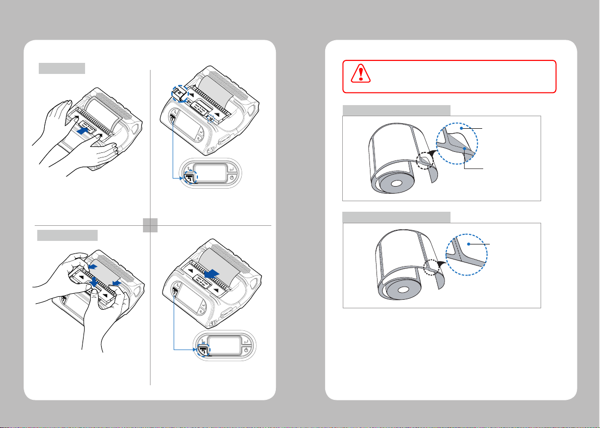
4-11. Peel Mode
Peel Mode
When users operates the peeler like the image below that has slits
on the label(1) and the perforated label(2), there might be an error
in the peeler function
CAUTION
Paper (1)
Label Paper
Engraved Line
With a roll of stock installed, slide the
peeler body towards the back of the
printer.
Non-Peel Mode
Pull down the Peeler Wing while pressing
the Cover open button slightly.
20
Push the peeler body until you see
two complete triangles.
Press the Feed button.
1 2
1 2
Press the Feed button.
Paper (2)
Label Paper
21

4-12. Shoulder Strap Installation
Optional
4-13. Diagnostic Test
Insert the strap into the hook of the printer.
Place the end of the strap into the hook
of shoulder strap.
22
1
32
After pulling out the end of the strap tightly,
put it into the clip to be fastened.
Turn off the printer.
The information label prints.
Press and hold the Feed button
and Power button.
1 2
3
NOTE
1. For Hex Dump mode, do steps 1-2 then
press the Feed button.
2. After printing ASCII pattern, the diagnostic
test is complete.
3. If the Feed button is not pressed to go to
Hex Dump mode, the printer exits
diagnostics after three seconds.
23

5. Peripherals Connection
The Sample of Self-test Printout
Upon initial installation or for troubleshooting, you can run the diagnostic test to
get information about:
Firmware version, emulation, codepage, sensor settings, interface settings, etc.
If no issues are found with diagnostic test, examine other devices and software.
The diagnostic test is working independent of devices and software.
●
Do Not Overheat the Motor
To prevent the motor from overheating, stop the printer for at least 30 seconds after
continuously printing 1.5 meters.
This printer can communicate with peripherals device via Bluetooth and Cables.
5-1 Bluetooth Connection
1. Printer can be connected to the PDA and PC which can do wireless communication.
2. By using Bluetooth function supported in PC, printer can be connected.
NOTE
Refer to the System Administrator Guide for more information.
24
25

6. Printer Cleaning
5-2. Interface Cable Connection
USB
Serial
1. Connect the USB or Serial cable to the cable connector on the printer.
NOTE
Use cable only offered by the printer manufacturer.
2. Connect the interface cable into the USB or Serial port of the device
(PDA, PC, etc.)
If the interior of the printer is dusty, printing quality can be lowered.
In this case, follow the instructions below to clean the printer.
6-1. Print-Head Cleaning
1. Use an applicator swab moistened with an isopropyl alcohol to clean the
print-head and remove any dust.
2. Once cleaning is complete, allow the printer to dry then install the stock
and close the cover.
Print-Head
NOTE
1. Make sure to turn the printer power off prior to cleaning.
2. The print-head can become very hot during printing;
allow the printer approximately10 minutes to cool before cleaning.
3. Do not touch the print-head, it can be damaged by static electricity.
4. Take care not to allow the print head to become scratched and /or damaged
in any way.
26
27

6-2. Platen Roller Cleaning
1.Clean the platen roller with a clean soft cloth moistened with isopropyl
alcohol or a cleaning pen.
2. Turn the platen roller with your nger to clean the
Platen Roller
7. Printer Specication
7-1. Specication
Printing Method Direct Thermal
Printing Speed 80mm/sec
Resolution 203 DPI X 203 DPI
Character ALPHA NUMERIC Character, Extension Character
Barcode One-Dimensional
Emulation ESC/POS, ZPL, CPCL Command compatible
Driver Windows (2000, XP, Vista, 7, 8), Symbian OS
Sensor Black-Mark Upper/Lower, Gap, Cover open,
Paper Paper Type Thermal Paper
Reliability TPH 50km
MEMORY Up to Flash 32MB
Communications standard Serial(RS-232C), USB
Barcodes
Two-Dimensional
Barcodes
Stacked OneDimensional
Barcodes
Width 50~112mm
Thickness Roll : 0.06 ~ 0.165 mm / Fanfold : 0.06~0.15 mm
External Diameter Max. Φ 58mm
Internal Diameter 12.5mm±0.5mm
Battery Continuous Printing 62min
Optional Bluetooth Class2
UPCA +2/+5, UPCE +2/+5, EAN8 +2/+5,
EAN13 +2/+5, EAN 128, Interleaved 2 of 5,
Extended Code 39, Codabar (NW7), Code 128,
Code 93, PostNet
PDF417, MaxiCode, Aztec, QR Code (Quick Response),
Datamatrix
GS1 Databar (RSS or Composite Code)
Windows mobile(Pocket PC, 2003, 6x), Android,
Windows CE 4.2/5.0/6.0, Linux, Blackberry
Peeler Detect, Peeler S/W, Media-Width Detect
Standby for 60hours
Printing Length: 140M
28
29

8. CPCL Command Compatibility
Display TFT-LCD (RGB) 240X400
Adaptor Input AC 100 ~240V 50/60Hz
Output 9.0V, 4.0A
Battery Battery Type Li-ion
Output STANDARD : 7.4V, 2600 mAh/19.24Wh
Charging Time 3.3 Hrs Charging
Size WXDXH(mm) 166X 174 X 80
WXDXH” 6.5 X 6.8 X 3.1
Weight 1Kg (With battery)
Environment Sealing IP54
Temperature Operation -21~ 55℃
Storage -30 ~ 65℃
Humidity Operation 10 ~ 90%
Storage 10 ~ 90%
OPTION : 7.4V, 5200 mAh/38.48Wh
NOTE
Compatible with only
Compatible
○
Printer Commands Compatibility
PRINT
FORM
JOURNAL
UNITS
USING COMMENTS
TEXT Compatibility
TEXT
FONT-GROUP(FG)
TEXT CONCATENATION
MULTILINE(ML)
COUNT
SETMAG
SCALABLE TEXT Compatibility
SCALE-TEXT
SCALABLE CONCATENATION
LINEAR BARCODES Compatibility
BARCODE
BARCODE-TEXT
COUNT
Two-Dimensional Bar Codes Compatibility
PDF417 (PORTABLE DATA FILE)
MICROPDF-417
MAXICODE
QRCODE
commanders provided by
the manufacturer.
●
Partially
Compatible
△
Not Compatible
○
○
○
○
○
○
○
○
○
○
○
○
○
○
○
○
○
●
○
○
x
30
31

DATAMATRIX
GS1(RSS-14)
AZTEC
GRAPHICS Compatibility
BOX
LINE
INVERSE-LINE
PATTERN
GRAPHICS
PCX
Advanced Commands Compatibility
CONTRAST
TONE
JUSTIFICATION
PAGE-WIDTH
PACE
NO-PACE
WAIT
SPEED
SETSP
ON-FEED
PREFEED
POSTFEED
COUNTRY/CODE PAGE
FORMAT FILES
BEEP
Line Print Mode Compatibility
SETLP
SETLF
Moving With X and Y Coordinates
LMARGIN
●
○
○
○
○
○
○
○
○
○
○
○
○
○
○
○
○
○
○
○
○
○
○
○
○
○
○
○
SETBOLD
SETSP
Special ASCII Characters
SETFF
SET-TOF
SETLP-TIMEOUT
ADVANCED UTILITIES Compatibility
VERSION
CHECKSUM
DEL
DIR
DEFINE-FILE
TYPE
BAUD
COUNTRY / CODE-PAGE
TIMEOUT
BEED
ON-LOW-BATTERY
LT
SET-TIME
GET-TIME
SET-DATE
GET-DATE
PRINTING A TIME STAMP
PRINTING A DATE STAMP
PAPER-JAM
PRINTER ESCAPE Compatibility
SET AND READ CODE
STATUS / INFROMATION
USER LABEL COUNT
POWER OFF
○
○
○
○
○
○
○
○
○
○
○
○
○
○
○
○
○
○
○
○
○
○
○
○
○
△
○
○
○
32
33

9. ESC / POS Command Compatibility
Command Function
HT Horizontal tab
LF Print and line feed
CR Print and carriage return
FF Print end position label to start printing
CAN Cancel print data in page mode
DLE EOT Real-time status transmission
DLE ENQ Real-time request to printer
ESC FF Print data in page mode
ESC SP Set character right-side spacing
ESC ! Set print mode
ESC $ Set absolute print position
ESC % Select/cancel user-defined character set
ESC & Define user-defined characters
ESC * Set bit image mode
ESC - Turn underline mode on/off
ESC 2 Set 1/6 inch line spacing
ESC 3 Set line spacing using minimum units
ESC ? Cancel user-defined characters
ESC @ Initialize printer
ESC D Set horizontal tab positions
ESC E Select emphasized mode
ESC G Select double-strike mode
ESC J Print end feed paper using minimum units
ESC L Select page mode
ESC M Select character font
ESC R Select international character set
ESC S Select standard mode
ESC T Select print direction in page mode
ESC V Set/cancel 90˚ cw rotated character
ESC W Set printing area in page mode
Compatibility
○
○
○
○
○
○
○
○
○
○
○
○
○
○
○
○
○
○
○
○
○
○
○
○
○
○
○
○
○
○
Command Function
ESC\ Set relative position
ESC a Align position
ESC d Print and feed paper n lines
ESC t Select character code table
ESC { Set/cancel upside-down character printing
FS p Print NV bit image
FS q Define NV bit image
GS ! Select character size
GS $ Set absolute vertical print position in page mode
GS * Define downloaded bit image
GS / Print down-loaded bit image
GS B Turn white/black reverse printing mode on/off
GS H Select printing position of HRI characters
GS I Transmit printer ID
GS L Set left margin
GS W Set printing area width
GS\ Set relative vertical print position in page mode
GS a Enable/disable Automatic Status Back(ASB)
GS f Select font for HRI characters
GS h Set bar code height
GS k Print bar code
GS r Transmit status
GS v 0 Print raster bit image
GS w Set bar code width
GS S C Set Serial Baudrate
DLE EOT n Selects card read mode / Cancel card read mode
GS S P Power Save Mode
Compatibility
○
○
○
○
○
○
○
○
○
○
○
○
○
○
○
○
○
○
○
○
○
○
○
○
○
○
○
34
35

10. ZPL Command Compatibility
Command Compatibility
^A
^B0
^B1
^B2
^B3
^B4
^B5
^B6
^B7
^B8
^B9
^BA
^BB
^BC
^BD
^BE
^BF
^BI
^BJ
^BK
^BL
^BM
^BO
^BP
^BQ
^BR
^BS
^BT
^BU
○
○
○
○
○
○
○
○
○
○
○
○
○
○
○
○
○
○
○
○
○
○
○
○
○
○
○
○
○
Command Compatibility
^BX
^BY
^BZ
^CC ~CC
^CD
^CF
^CI
^CT ~CT
~DF
~DG
^FB
^FC
^FD
^FH
^FN
^FO
^FP
^FR
^FS
^FT
^FV
^FW
^FX
^GB
^GC
^GD
^GE
^GF
^GS
○
○
○
○
○
○
○
○
○
○
○
○
○
○
○
○
○
○
○
○
○
○
○
○
○
○
○
○
○
36
37

Command Compatibility
^ID
^IL
^IM
^IS
~JR
^JS
~JS
^KL
^LH
^LL
^LR
^LS
^LT
^MC
^MD
^MN
^PM
^PO
^PQ
^PR
~PR
^PW
^SC
^SD
^SF
^SL
^SN
^SO
^ST
○
○
○
○
○
○
○
○
○
○
○
○
○
○
○
○
○
○
○
○
○
○
○
○
○
○
○
○
○
Command Compatibility
~TA
^XA
^XF
^XG
^XZ
^ZZ
○
○
○
○
○
○
38
39

40
 Loading...