

Page 1
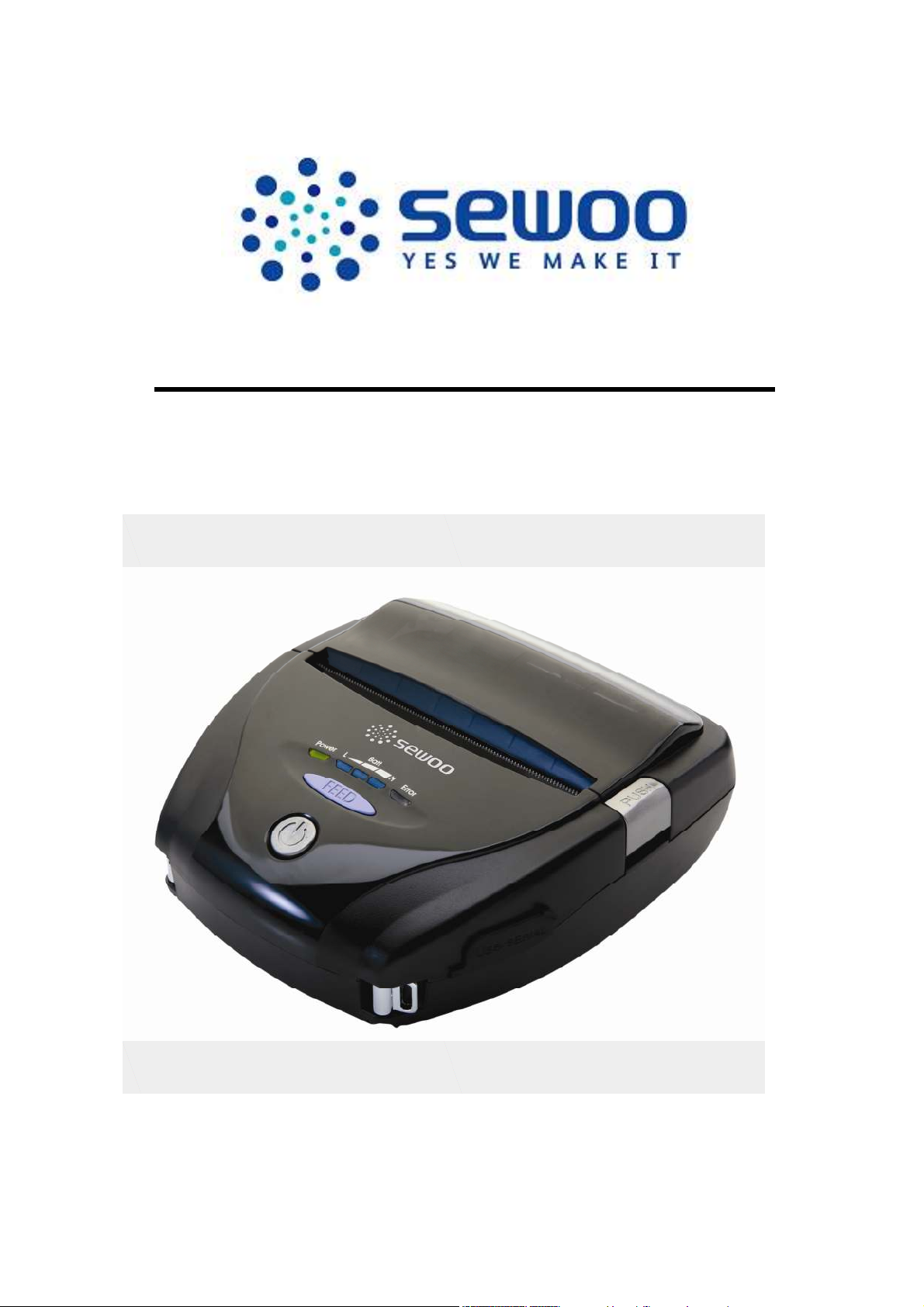
LK-P41
Mobile Receipt Printer
ESC/POS Command Manual
SEWOO TECH CO., LTD.
www.miniprinter.com
Page 2
ESC/POS Command Manual
1. Control Command summary
No. Command Function
1 HT Horizontal tab
2 LF Print and line feed
3 CR Print and carriage return
4 FF Print end position label to start printing
5 CAN Cancel print data in page mode
6 DLE EOT Real-time status transmission
7 DLE ENQ Real-time request to printer
8 ESC FF Print data in page mode
9 ESC SP Set character right-side spacing
10 ESC ! Set print mode
11 ESC $ Set absolute print position
12 ESC % Select/cancel user-defined character set
13 ESC & Define user-defined characters
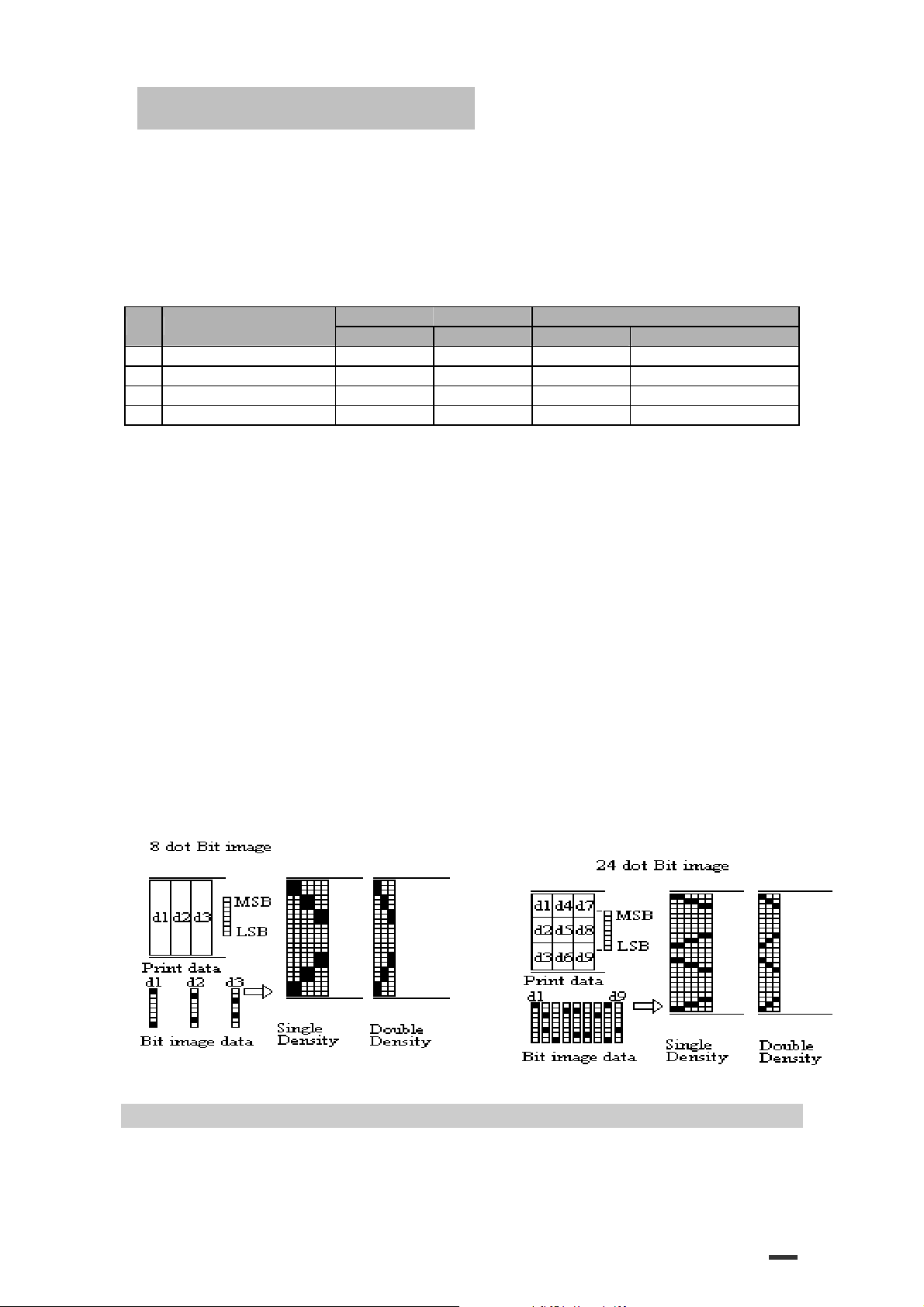
14 ESC * Set bit image mode
15 ESC - Turn underline mode on/off
16 ESC 2 Set 1/6 inch line spacing
17 ESC 3 Set line spacing using minimum units
18 ESC ? Cancel user-defined characters
19 ESC @ Initialize printer
20 ESC D Set horizontal tab positions
21 ESC E Select emphasized mode
22 ESC G Select double-strike mode
23 ESC J Print end feed paper using minimum units
24 ESC L Select page mode
25 ESC M Select character font
26 ESC R Select international character set
27 ESC S Select standard mode
28 ESC T Select print direction in page mode
29 ESC V Set/cancel 90° cw rotated character
30 ESC W Set printing area in page mode
31 ESC \ Set relative position
32 ESC a Align position
33 ESC d Print and feed paper n lines
34 ESC t Select character code table
35 ESC { Set/cancel upside-down character printing
36 FS p Print NV bit image
37 FS q Define NV bit image
38 GS ! Select character size
39 GS $ Set absolute vertical print position in page mode
40 GS * Define downloaded bit image
41 GS / Print down-loaded bit image
42 GS B Turn white/black reverse printing mode on/off
43 GS H Select printing position of HRI characters
44 GS I Transmit printer ID
45 GS L Set left margin
46 GS W Set printing area width
47 GS \ Set relative vertical print position in page mode
48 GS a Enable/disable Automatic Status Back(ASB)
49 GS f Select font for HRI characters
2
Page 3
ESC/POS Command Manual
50 GS h Set bar code height
51 GS k Print bar code
52 GS r Transmit status
53 GS v 0 Print raster bit image
54 GS w Set bar code width
3
Page 4

ESC/POS Command Manual
2. Command Descriptions
Command Descriptions
Command Notation
[Name] The name of the control command.
[Format] The code sequence.
In this description, < > H denotes hexadecimal numbers, < >denotes
decimal numbers and < > B denotes binary numbers.
[ ] k indicates the contents of the [ ] should be repeated k times.
[Range] The allowable range for the arguments.
[Description] Description of the command function.
[Details] If necessary provides important information on setting and using the printer command.
[Default] The default values for the commands.
[Reference] List related commands.
[Example] Example of using the commands.
The numbers denoted by <>H is hexadecimal.
The numbers denoted by <>B is binary.
4
Page 5

ESC/POS Command Manual
3. Print Commands
The LK-Px series supports the following commands for printing characters and advancing paper.
HT
[Name] Horizontal tab
[Format] ASCII HT
Hex 09
Decimal 9
[Description] Moves the print position to the next tab position.
[Details] ·This command is ignored unless the next tab position has been set.
·If the next horizontal tab position exceeds the printing area, the printer
sets the printing position to [Printing area width + 1].
·Horizontal tab positions are set using “ESC D”.
·If this command is received when the printing position is at [printing area width +1], the printer
executes print buffer-full printing of the current line and horizontal tab processing from the
beginning of the next line.
·The default setting of the horizontal tab position for the paper roll is font A
(12 x 24) every 8th character (9th, 17th, 25th, … column).
[Reference] ESC D
LF
[Name] Print and line feed
[Format] ASCII LF
Hex 0A
Decimal 10
[Description] ·Prints the data in the print buffer and feeds one line based on the current
line spacing.
[Details] ·This command sets the print position to the beginning of the line.
[Reference] ESC 2, ESC 3
CR
[Name] Print and carriage return.
[Format] ASCII CR
Hex 0D
Decimal 13
[Description] When automatic line feed is enabled, this command functions the same as LF; when automatic
line feed is disabled, this command is ignored.
5
Page 6

ESC/POS Command Manual
[Details] ·Sets the print starting position to the beginning of the line.
·The automatic line feed is ignored.
[Reference] LF
FF
[Name] Print and return to standard mode in page mode.
[Format] ASCII FF
Hex 0C
Decimal 12
[Description] Prints the data in the print buffer and returns to standard mode.
[Details] ·The buffer data is deleted after being printed.
·The printing area set by ESC W is reset to the default setting.
·The printer does not execute paper cutting.
·This command sets the print position to the beginning of the line.
·This command is enabled only in page mode.
[Reference] ESC FF, ESC L, ESC S
CAN
[Name] Cancel print data in page mode
[Format] ASCII CAN
Hex 18
Decimal 24
[Description] In page mode, delete all the print data in the current printable area.
[Details] ·This command is enabled only in page mode.
·If data that existed in the previously specified printable area also exists in
the currently specified printable area, it is deleted.
[Reference] ESC L, ESC W
DLE EOT n
[Name] Real-time status transmission.
[Format] ASCII DLE EOT
Hex 10 04
Decimal 16 4
[Range] 1≤n≤4
[Description] Transmits the selected printer status specified by n in real-time,
according to the following parameters:
n
=1 : Transmit printer status
n
n
n
6
Page 7
ESC/POS Command Manual
n=2 : Transmit off-line status
n
[Details] ·The printer transmits the current status. Each status is represented by one-byte data.
·The printer transmits the status without confirming whether the host computer can receive data.
·The printer executes this command upon receiving it.
·This command is executed even when the printer is offline, the receive buffer is full,
[Notes] ·The status is transmitted whenever the data sequence of <10>H<04>H<n> (1≤n≤4) is received.
n
= 1: Printer status
Bit Off/On Hex Decimal Function
0 Off 00 0 Not used. Fixed to Off
1 On 02 2 Not used. Fixed to On
Off 00 0 2
On 04 4
Off 00 0 On-line 3
On 08 8 Off-line.
4 On 10 16 Not used. Fixed to On
5,6 - - - Undefined.
7 Off 00 0 Not used. Fixed to Off.
n
= 2: Off-line status
Bit Off/On Hex Decimal Function
0 Off 00 0 Not used. Fixed to Off
1 On 02 2 Not used. Fixed to On
Off 00 0 Cover is closed 2
On 04 4 Cover is open
Off 00 0 Paper is not being fed by using the FEED button 3
On 08 8 Paper is being fed by the FEED button
4 On 10 16 Not used. Fixed to On
Off 00 0 No paper-end stop 5
On 20 32 Printing is being stopped
Off 00 0 No error 6
On 40 64 Error occurs
7 Off 00 0 Not used. Fixed to Off
Bit 5: Becomes on when the paper end sensor detects paper end and printing stops.
=3 : Transmit error status
n
=4 : Transmit paper roll sensor status
or there is an error status.
·When Auto Status Back (ASB) is enabled using the GS a command, the status transmitted by the
DLE EOT command and the ASB status must be differentiated.
Example :
In ESC *
m nL nH d1…dk
d1=<10>H, d2=<04>H, d3=<01>H
·This command should not be used within the data sequence of another command that consists
of 2 or more bytes.
Example :
If you attempt to transmit ESC 3 n to the printer, but DTR (DSR for the host computer)
goes to MARK before
n
is transmitted and then DLE EOT 3 interrupts before n is
received, the code <10> H for DLE EOT 3 is processed as the code for ESC 3 <10>H.
7
Page 8
ESC/POS Command Manual
= 3: Error status
n
Bit Off/On Hex Decimal Function
0 Off 00 0 Not used. Fixed to Off
1 On 02 2 Not used. Fixed to On
2 - - - Undefined
Off 00 0 3
On 08 8
4 On 10 16 Not used. Fixed to On
Off 00 0 No unrecoverable error 5
On 20 32 Unrecoverable error occurs
Off 00 0 No auto-recoverable error 6
On 40 64 Auto recoverable error occurs
7 Off 00 0 Not used. Fixed to Off
Bit 3: If these errors occur due to paper jams or the like, it is possible to recover by correcting the cause of the error
and executing DLE ENQ n (1 ≤ n ≤ 2). If an error due to a circuit failure (e.g. wire break) occurs, it is impossible
to recover.
Bit 6: When printing is stopped due to high print head temperature until the print head temperature drops sufficiently
or when the paper roll cover is open during printing, bit 6 is On.
n
= 4: Continuous paper sensor status
Bit Off/On Hex Decimal Function
0 Off 00 0 Not used. Fixed to Off
1 On 02 2 Not used. Fixed to On
Off 00 0 Paper roll sensor: paper adequate 2,3
On 0C 12 Paper roll end detected by the paper roll sensor.
4 On 10 16 Not used. Fixed to On
Off 00 0 Paper roll sensor: Paper present 5,6
On 60 96 Paper roll end detected by the paper roll sensor
7 Off 00 0 Not used. Fixed to Off
[Reference] DLE ENQ, GS a, GS r
DLE ENQ n
[Name] Real-time request to printer
[Format] ASCII DLE ENQ n
Hex 10 05 n
Decimal 16 5 n
[Range] 1≤n≤2
[Description] Responds to a request from the host computer.
n
specifies the requests as follows:
n Request
1 Recover from an error and restart printing from the line where the error occurred
2 Recover from an error aft clearing the receive and print buffers
[Details]
·This command is effective only when an auto-cutter error occurs.
·The printer starts processing data upon receiving this command.
·This command is executed even when the printer is offline, the receive buffer is full, or there is an
error status with a serial interface model.
8
Page 9

ESC/POS Command Manual
·The status is also transmitted whenever the data sequence of <10>H<05>H< n> (1≤n≤2) is
received.
Example:
In ESC * ** * m nL nH dk, d1 = <10>H, d2 = <05>H, d3 = <01>H
·This command should not be contained within another command that consists of two or more
bytes.
Example:
If you attempt to transmit ESC 3 n to the printer, but DTR (DSR for the host computer)
goes to MARK before n is transmitted, and DLE ENQ 2 interrupts before n is received,
the code <10>H for DLE ENQ 2 is processed as the code for ESC 3 <10>H.
[Reference] DLE EOT
ESC FF
[Name] Print data in page mode
[Format] ASCII ESC FF
Hex 1B 0C
Decimal 27 12
[Description] In page mode, prints all buffered data in the printable area collectively.
[Details] ·This command is enabled only in page mode.
·After printing, the printer does not clear the buffered data, setting value for ESC T and ESC W,
and the position for buffering character data.
[Reference] FF, ESC L, ESC S
ESC SP n
[Name] Set right-side character spacing
[Format] ASCII ESC SP
Hex 1B 20
Decimal 27 32
n
[Range] 0≤
[Description] Sets the character spacing for the right side of the character to
[Details] ·The right-side character spacing for double-width mode is twice the normal value.
·In standard mode, the horizontal motion unit is used.
≤255
[
n
x horizontal or vertical motion units].
When characters are enlarged, the right-side character spacing is
·This command does not affect the setting of Kanji characters.
·This command sets values independently in each mode (standard and page modes).
n
n
n
n
times normal value.
9
Page 10
ESC/POS Command Manual
·In page mode, the horizontal or vertical motion unit differs in page mode, depending on starting
position of the printable area as follows:
When the starting position is set to the upper left or lower right of the printable area using ①
ESC T, the horizontal motion unit (x) is used.
When the starting position is set to the upper right or lower left of the printable area using ②
ESC T, the vertical motion unit (y) is used.
·The maximum right-side spacing is 35.983 mm {255/180”}. Any setting exceeding the
maximum is converted to the maximum automatically.
n
[Default]
[Reference]
ESC ! n
[Name] Select print mode(s)
[Format] ASCII ESC !
Hex 1B 21
Decimal 27 33
[Range] 0≤n ≤255
[Description] Selects print mode(s) using n as follows:
Bit Off/On Hex Decimal Function
1 - - - Undefined.
2 - - - Undefined.
6 - - - Undefined.
[Details] ·When both double-height and double-width modes are selected,
= 0
n
n
n
Off 00 0 Character font A (12x24) 0
On 01 1 Character font B (9x17)
Off 00 0 Emphasized mode not selected. 3
On 08 8 Emphasized mode selected.
Off 00 0 Double-height mode not selected. 4
On 10 16 Double-height mode selected.
Off 00 0 Double-width mode not selected. 5
On 20 32 Double-width mode selected.
Off 00 0 Underline mode not selected. 7
On 80 128 Underline mode selected.
quadruple size characters are printed.
·The printer can underline all characters, but can not underline the space set by HT or 90°
clockwise rotated characters.
·The thickness of the underline is selected by ESC-, regardless of the character size.
·When some characters in a line are double or more height, all the characters on the line are
aligned at the baseline.
10
Page 11

ESC/POS Command Manual
·ESC E Can also turn on or off emphasized mode. However, the setting of the last received
command is effective.
·ESC - Can also turn on or off underline mode. However, the setting of the last received command
effective.
·GS ! Can also select character size, However, the setting of the last received command is
effective.
·Emphasized mode is effective for alphanumeric and Kanji. All print modes except emphasized
mode is effective only for alphanumeric.
n
[Default]
[Reference] ESC E, ESC -, GS !
ESC $
[Name] Set absolute print position
[Format] ASCII ESC $
Hex 1B 24
Decimal 27 36
[Range] 0≤nL≤255
0≤
[Description] Sets the distance from the beginning of the line to the position at which subsequent characters
[Details] ·The distance from the beginning of the line to the print position is
·Settings outside the specified printable area are ignored.
[Reference] ESC \, GS $, GS \
nL n
H
ESC % n
[Name] Select/cancel user-defined character set
[Format] ASCII ESC %
Hex 1B 25
Decimal 27 37
[Range] 0≤n ≤255
[Description] Selects or cancels the user-defined character set
·When the LSB of n is 0, the user-defined character set is canceled.
= 0
nL n
nL n
nL n
nH
≤255
are to be printed.
n
L
+
n
H
x 256) x (vertical or horizontal motion unit)] inches.
[(
·In page mode, the horizontal or vertical motion unit differs depending on the starting position of
the printable area as follows :
1. When the starting position is set to the upper left or lower right of the printable area using
ESC T, the horizontal motion unit (x) is used.
2. When the starting position is set to the upper right or lower left of the printable area using
ESC T, the vertical motion unit (y) is used.
n
n
n
·When the LSB of n is 1, the user-defined character set is selected.
H
H
H
11
Page 12
ESC/POS Command Manual
[Details] ·When the user-defined character set is canceled,
the internal character set is automatically selected.
·n is available only for the least significant bit.
[Default] n = 0
[Reference] ESC &, ESC ?
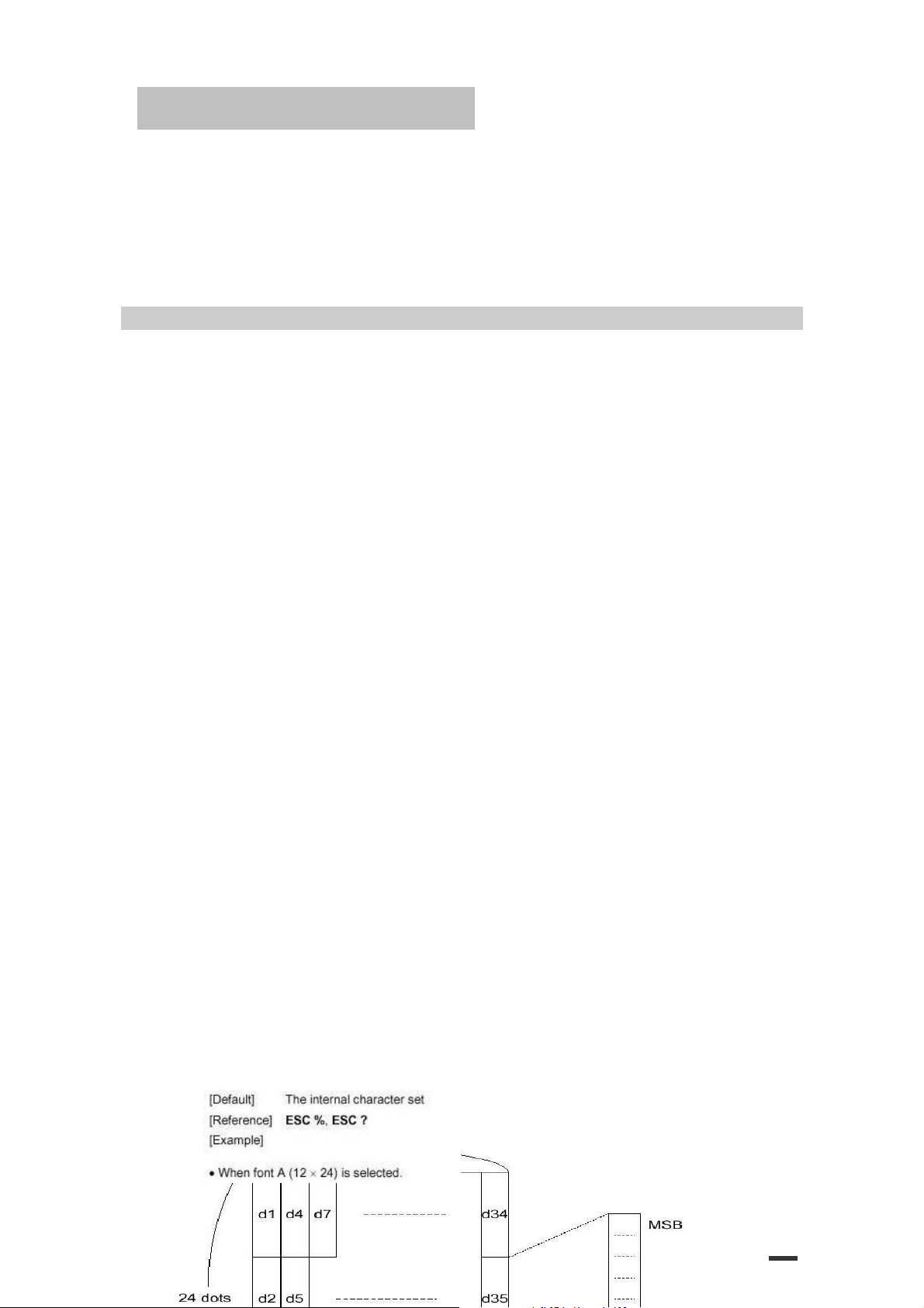
ESC & y c1 c2 [x1 d1…d(y x x1)]..[ xk d1..d(y x xk)]
[Name] Define user-defined characters
[Format] ASCII ESC & y c1 c2
Hex 1B 26 y c1 c2
Decimal 27 38 y c1 c2
[Range]
[Description] Defines user-defined characters
[Details] ·The allowable character code range is from ASCII code <20>H to <7E>(95characters).
y
= 3
c1
≤ c2 ≤ 126
32 ≤
0 ≤ x ≤ 12 Font A (when font A (12 x 24) is selected)
0 ≤ x ≤ 9 Font B (when font B (9 x 17) is selected)
0 ≤ d1 ... d(
·y specifies the number of bytes in the vertical direction.
·c1 specifies the beginning character code for the definition, and c2 specifies the final code.
·X specifies the number of dots in the horizontal direction.
·It is possible to define multiple characters for consecutive character codes.
·If only one character is desired, use c1 = c2.
·d is the dot data for the characters. The dot pattern is in the horizontal direction from the left side.
Any remaining dots on the right side are blank.
·The data to define a user-defined character is (y × x) bytes.
·Set a corresponding bit to 1 to print a dot or 0 to not print a dot.
·This command can define different user-defined character patterns by each fonts. To select a
font, use ESC !
·A user-defined character and a downloaded bit image cannot be defined simultaneously.
When this command is executed, the downloaded bit image is cleared.
·The user-defined character definition is cleared when:
·When the user-defined characters are defined in font B (9 x 24), only the most significant bit of
the 3rd byte of data in vertical direction is effective.
y
x xk) ≤ 255
① ESC @ is executed.
② ESC ? is executed.
③ FS q is executed.
④ GS * is executed.
The printer is reset or the power is turned off.⑤
[x1 d1...d(y × x1)]...[xk d1...d(y × xk)]
[x1 d1...d(y × x1)]...[xk d1...d(y × xk)]
[x1 d1...d(y × x1)]...[xk d1...d(y × xk)]
12
Page 13
ESC/POS Command Manual
ESC *
[Name] Select bit-image mode
[Format] ASCII ESC *
m nL n
H
[
d1...dk]
m nL n
H
d1...dk
13
Page 14
ESC/POS Command Manual
Hex 1B 2A
Decimal 27 42
[Range]
0≤
0≤
0≤
[Description] Selects a bit-image mode using
m
Mode
0 8-dot single-density 8 60 DPI 90 DPI
1 8-dot double-density 8 60 DPI 180 DPI
32 24-dot single-density 24 180 DPI 90 DPI (
33 24-dot double-density 24 180 DPI 180 DPI
[dpi : dots per 25.4 mm{1”}]
[Details] ·If the values of m is out of the specified range,
m =
0, 1, 32, 33
n
L
≤255
n
H
≤3
d
≤255
Vertical Direction Horizontal Direction
NO. of Dots Dot Density Dot Density Number of (Data(K)
nL and data following are processed as normal data.
nL
and nH indicate the number of dots of the bit image in the horizontal direction.
·The
The number of dots is calculated
·If the bit-image data input exceeds the number of dots to be printed on a line,
the excess data is ignored.
d
indicates the bit-image data. Set a corresponding bit of 1 to print a dot or to 0 to not print a dot.
·
·If the width of the printing area set by GS L and GS W less than the width required by the data
sent with the ESC *command the following will be performed on the line in question (but the
printing cannot exceed the maximum printable area) :
The width of the printing area is extended to the right to accommodate the amount of ①
data.
If step does not provide suffici② ① ent width for the data,
the left margin is reduced to accommodate the data.
·After printing a bit image, the printer returns to normal data processing mode.
·This command is not affected by print modes(emphasized, double-strike, underline,
character size or white/black reverse printing), except upside-down printing mode.
·Refer to Figure 3.12.3 for the bit image development position in page mode.
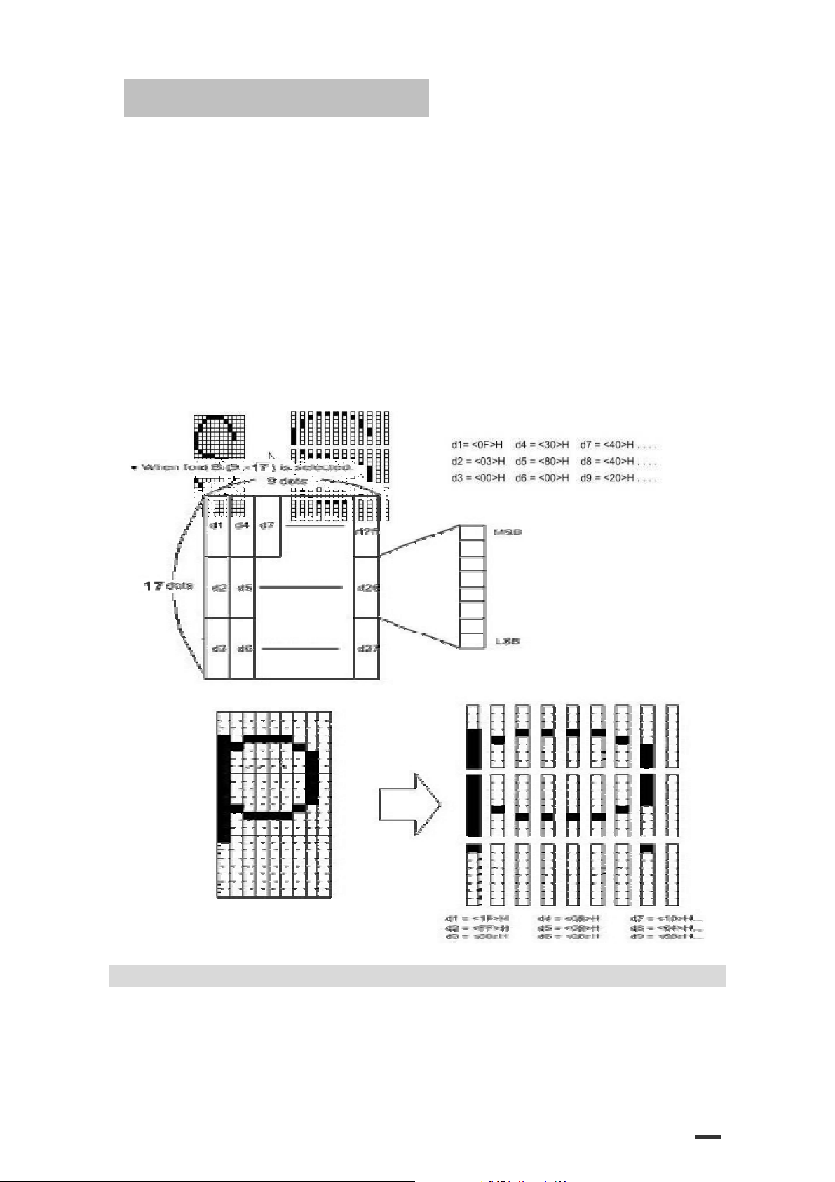
·The relationship between the image data and the dots to be printed is as follows:
·When 8-dot bit image is selected:
ESC - n
[Name] Turn underline mode on/off
m nL n
m nL n
m
for the number of dots specified by nL and nH, as follows:
by nL + nH x 256
H
H
.
d1...dk
d1...dk
nL + nH x 256
nL + nH x 256
nL + nH x 256) x 3
(nL + nH x 256) x 3
14
Page 15

ESC/POS Command Manual
[Format] ASCII ESC -
Decimal 27 45
Hex 1B 2D
[Range] 0≤n ≤2, 48≤n ≤50
[Description] Turns underline mode on or off, based on the following values of n.
n
Function
0, 48 Turns off underline mode
1, 49 Turns on underline mode (1-dot thick)
2, 50 Turns on underline mode (2-dots thick)
[Details] ·The printer can underline all characters (including right-side character spacing),
but cannot underline the space set by HT.
·The printer cannot underline 90˚ clockwise rotated characters and white/black inverted
characters.
·When underline mode id turned off by setting the value of
underlined, and the underline thickness set before the mode is turned off does not change. The
default underline thickness is 1 dot.
·Changing the character size does not affect the current underline thickness.
·Underline mode can also be turned on or off by using ESC!. Note, however, that the last received
command is effective.
·This command does not affect Kanji printing.
n
[Default]
[Reference] ESC !
= 0
ESC 2
[Name] Select default line spacing
[Format] ASCII ESC 2
Hex 1B 32
Decimal 27 50
[Description] Selects approximately 4.23 mm {1/6”} spacing.
[Details] ·The line spacing can be set independently in standard mode and in page mode.
[Reference] ESC 3
ESC 3
[Name] Set line spacing
[Format] ASCII ESC 3
Hex 1B 33
Decimal 27 51
[Range] 0≤
n
n
≤255
n
n
n
n
n
to 0 or 48, the following data is not
n
n
15
Page 16

ESC/POS Command Manual
n
[Description] Sets the line spacing to [
[Details] ·The line spacing can be set independently in standard mode and in page mode.
·In standard mode, the vertical motions until (y) is used.
·In page mode, this command function as follows,
depending on the starting position of the printable area :
When the starting position is set to the upper left or lower right to the printable area ①
using ESC T, the vertical motion unit
When the starting position is set to the upper right or lower left of ②
the printable area using ESC T, the horizontal motion unit
·The maximum paper feed amount is 1016 mm {40”}. Even if a paper feed amount of more than
1016 mm{40”}is set, the printer feeds the paper only 1016 mm{40”}
[Default] Line space is equivalent to approximately 4.23 mm{1/6”}.
[Reference] ESC 2
ESC ? n
[Name] Cancel user-defined characters
[Format] ASCII ESC ?
Hex 1B 3F
Decimal 27 63
[Range] 32 ≤n ≤126
[Description] Cancels user-defined characters.
[Details] ·This command cancels the pattern defined for the character code
[Reference] ESC &, ESC %
ESC @
[Name] Initialize printer
[Format] ASCII ESC @
Hex 1B 40
Decimal 27 64
specified by n. After the user-defined characters is canceled, the corresponding pattern for the
internal character is printed.
·This command deletes the pattern defined for the specified code in the font selected by ESC !.
·If a user-defined character has not been defined for the specified character code,
the printer ignores this command.
x (vertical or horizontal motion unit)] inches.
(y)
is used.
(x)
is used.
n
n
n
16
Page 17

ESC/POS Command Manual
[Description] Clears the data in the print buffer and resets the printer mode to the mode
that was in effect when the power was turned on.
[Details] ·The DIP switch settings are not checked again.
·The data in the receive buffer is not cleared.
·The macro definition is not cleared.
·The NV bit image data is not cleared.
·The data of the NV user memory is not cleared.
ESC D [n1...nk] NUL
[Name] Set horizontal tab positions
[Format] ASCII ESC D
Hex 1B 44
Decimal 27 68
[Range] 1≤n ≤255
0≤
[Description] Set is horizontal tab positions.
·
[Details] ·The horizontal tab position is stored as a value of [character width x
·This command cancels the previous horizontal tab settings.
·Transmit [
·ESC D NUL cancels all horizontal tab positions.
n1……nk NUL
n1……nk 00
n1……nk 0
k
≤32
n
specifies the column number for setting a horizontal tab position from the beginning of the line.
·
k
indicates the total number of horizontal tab positions to be set.
n
]
measured from the beginning of the line. The character width includes the right-side character
spacing, and double-width characters are set with twice the width of normal characters.
·When setting n = 8, the print position is moved to column 9 by sending HT.
·Up to 32 tab positions (
normal data.
n]k
in ascending order and place a NUL code 0 at the end.
n
·When [
·The previously specified horizontal tab positions do not change, even if the character width
·The character width is memorized for each standard and page mode.
]k is less than or equal to the preceding value [n]k-1, tab setting is finished and the
following data is processed as normal data,
changes.
k
=32) can be set. Data exceeding 32-tab positions s is processed as
17
Page 18

ESC/POS Command Manual
[Default] The default tab positions are at intervals of 8 characters (columns 9, 17, 25, ...) for the font A (12
X 24).
[Reference] HT
ESC E
n
[Name] Turn emphasized mode on/off
n
[Format] ASCII ESC E
Hex 1B 45
Decimal 27 69
n
[Range] 0≤
[Description] Turns emphasized mode on or off.
·When the LSB of
·When the LSB of
[Details] ·Only the least significant bit of n is enabled.
·This command and ESC! Turn on and off emphasized mode in the same way. Be careful when this
[Default]
[Reference] ESC !
ESC G
[Name] Turn on/off double-strike mode
[Format] ASCII ESC G
Hex 1B 47
Decimal 27 71
[Range] 0≤n ≤255
[Description] Turns double-strike mode on or off.
·When the LSB of
·When the LSB of
[Details] ·Only the lowest bit of n is enabled.
·Printer output is the same in double-strike mode and in emphasized mode.
[Default]
[Reference] ESC E
ESC J
n
n
≤255
n
is 0, emphasized mode is turned off.
n
is 1, emphasized mode is turned on.
command is used with ESC!.
n
= 0
n
is 0, double-strike mode is turned off.
n
is1, double-strike mode is turned on.
n
= 0
n
n
n
n
n
18
Page 19

ESC/POS Command Manual
[Name] Print and feed paper
n
[Format] ASCII ESC J
Hex 1B 4A
Decimal 27 74
n
[Range] 0≤
[Description] Prints the data in the print buffer and feeds the paper [n x vertical or horizontal motion unit].
[Details] ·After printing is completed, this command sets the print starting position
·In standard mode, the printer uses the vertical motion unit(
[Reference]
≤255
to the beginning of the line.
·The paper feed amount set by this command does not affect the values set by ESC 2 or ESC 3.
·In page mode, this command functions as follows, depending on the starting position of the
printable area.
When the starting position is set to the upper left or lower right of the printable area using ①
ESC T, the vertical motion unit (y) is used.
When the starting position is set to the upper right or lower left of the printable area using ②
ESC T, the horizontal motion unit (x) is used.
·The maximum line spacing is 1016 mm{40”}. When the setting value exceeds the maximum, it is
converted to the maximum automatically.
ESC L
[Name] Select page mode
[Format] ASCII ESC L
Hex 1B 4C
Decimal 27 76
[Description] Switches from standard mode to page mode.
[Details] ·This command is enabled only when input at the beginning of a line in standard mode.
·This command has no effect in page mode.
·After printing by FF is completed or by using ESC S, the printer returns to standard mode.
·This command sets the position where data is buffered to the position specified by ESC T within
the printing area defined by ESC W.
·This command is switches the setting for the following commands (in which the values can be set
independently in standard mode and page mode) to those for page mode.
Set right① -side character spacing : ESC SP, FS S
② Select default line spacing : ESC 2, ESC3
·Only valve settings is possible for the following commands in page
mode; these commands are not executed.
Turn 90① ° clockwise rotation mode on/off: ESC V
Select justification: ② ESC a
Turn upside③ -down printing mode on/off: ESC {
Set left margin: ④ GS L
Set printable area width: ⑤ GS W
·The following command is ignored in page mode:
Execute test print: ① GS W
·The following command is not available in page mode:
n
n
y
).
19
Page 20
ESC/POS Command Manual
① Print NV bit image : FS p
② Define NV bit image : FS q
③ Print raster bit image : GS v 0
·The printer returns to standard mode when power is turned on, the printer is reset, or ESC @ is
used.
[Reference] FF, CAN, ESC FF, ESC S, ESC T, ESC W, GS $, GS \
ESC M n
[Name] Select character font
[Format] ASCII ESC M n
Hex 1B 4D n
Decimal 27 77 n
[Range] n= 0, 1 , 48, 49
[Description] Selects character fonts
n
Function
0, 48 Character font A (12 X 24 ) Selected
1, 49 Character font B (9 X 24 ) Selected
[Details] ·The ESC ! command can also select the character fonts. However, the
setting of the last received command is effective.
[Reference] ESC !
ESC R
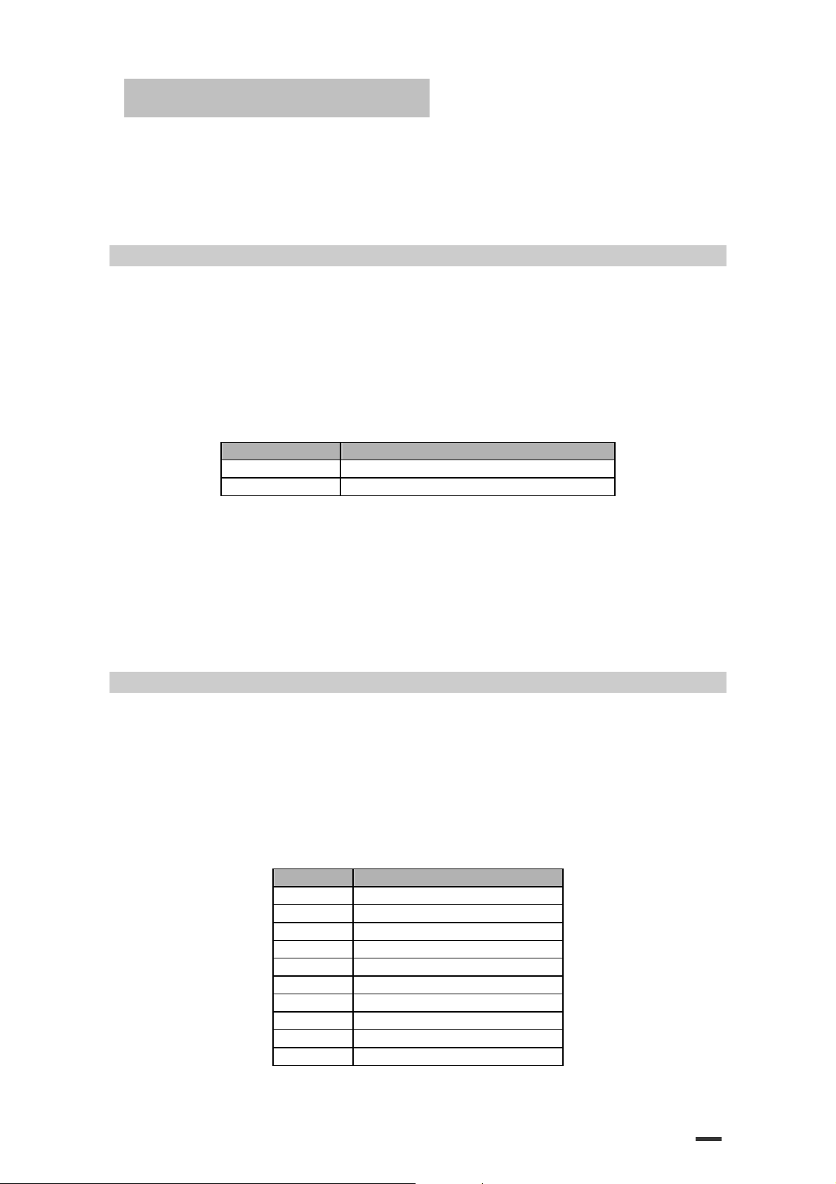
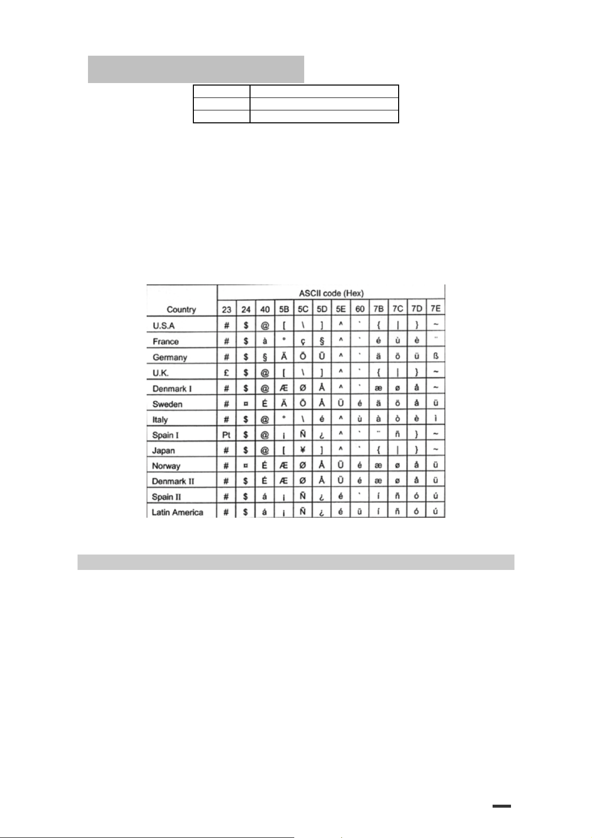
[Name] Select an international character set
[Format] ASCII ESC R
Hex 1B 52
Decimal 27 82
[Range] 0≤
[Description] Selects an international character set n from the following table:
n
n
≤13
n
n
n
n
Character Set
0 U. S. A
1 France
2 Germany
3 U. K.
4 Denmark I
5 Sweden
6 Italy
7 Spain I
8 Japan
9 Norway
20
Page 21
ESC/POS Command Manual
10 Denmark II
11 Spain II
12 Latin America
[Default]
[Reference] 3.2.12 International Character Set
n
= 0
ESC S
[Name] Select standard mode
[Format] ASCII ESC S
Hex 1B 53
Decimal 27 83
[Description] Switches from page mode to standard mode.
[Details] ·This command is effective only in page mode.
·Data buffered in page mode and the printable area developed in page mode are cleared.
·This command is switches the setting for the following command (in which the values can be set
independently in standard mode and page mode) to those for standard mode:
Set right① -side character spacing: ESC SP, FS S
Select default line spacing : ② ESC 2, ESC 3
·The following commands are enabled only to set in standard mode.
21
Page 22
ESC/POS Command Manual
Set printing area in page mode : ① ESC W
Set② print direction in page mode : ESC T
·The following commands are ignored in standard mode.
① Set absolute vertical print position in page mode : GS $
② Set relative vertical print position in page mode : GS \
·Standard mode is selected automatically when power is turned on, the
printer is reset, or command ESC @ is used.
[Reference] FF, ESC FF, ESC L
ESC T n
[Name] Select print direction in page mode
n
[Format] ASCII ESC T
Hex 1B 54
Decimal 27 84
[Range] 0≤
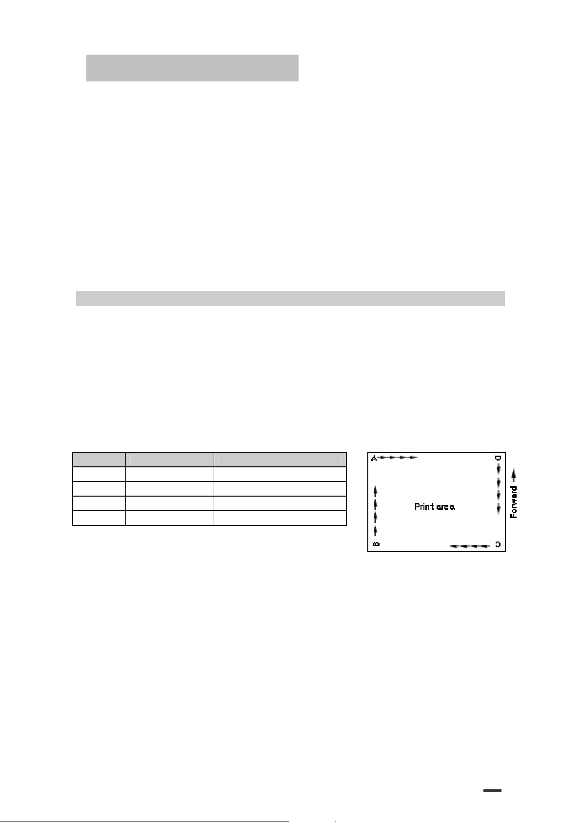
[Description] Select the print direction and starting position in page mode.
n
0, 48 Left to right Upper left(A in the figure)
1, 49 Bottom to top Lower left(B in the figure)
2, 50 Right to left Lower right(C in the figure)
3, 51 Top to bottom Upper right(D in the figure)
[Details] ·When the command is input in standard mode, the printer executes only
Commands using horizontal motion units: ESC SP, ESC $, ESC\
Commands using vertical motion units: ESC 3, ESC J, GS $, GS\
If the starting position is the upper right or lower left of the printing ②
n
≤3,
n
≤51
48≤
n
specifies the print direction and starting position as follows:
Print Direction Starting Position
internal flag operation. This command does not affect printing in standard
mode.
·This command sets the position where data is buffered within the printing area set by ESC W.
·Parameters for horizontal or vertical motion units
follows, depending on the starting position of the printing area:
If the starting position is the upper left or lower right of the printing ①
area, data is buffered in the direction perpendicular to the paper feed direction:
area, data is buffered in the paper feed direction :
Commands using horizontal motion units : ESC 3, ESC J, GS &, GS\
Commands using vertical motion units : ESC SP, ESC $, ESC\
n
n
(x or y)
differ as
22
Page 23

ESC/POS Command Manual
n
[Default]
[Reference] ESC $, ESC L, ESC W, ESC\, GS $, GS\
ESC V
n
[Name] Turn 90° clockwise rotation mode on/off
[Format] ASCII ESC V
Hex 1B 56
Decimal 27 86
[Range] 0≤
[Description] Turns 90° clockwise rotation mode on or off.
[Details] ·When underline mode is turned on, the printer does not underline 90° clockwise-rotated
[Default]
[Reference] ESC !, ESC –
ESC W
[Name] Set printing area in page mode
[Format] ASCII ESC W
Hex 1B 57
Decimal 27 87
[Range] 0≤
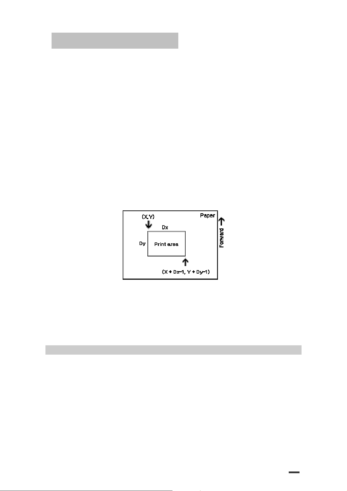
[Description] ·The horizontal starting position, vertical starting position, printing area width,
Each setting for the printable area is calculated as follow:
x0 = [(xL + xH x 256) x (horizontal motion unit)]
y0 = [(yL + yH x 256) x (vertical motion unit)]
xL xH yL yH dxL dxH dyL dyH
= 0
n
n
n
n
≤1,48≤n ≤49
n
is used as follows:
n Function
0, 48 Turns off 90˚ clockwise rotation mode
1, 49 Turns on 90˚ clockwise rotation mode
characters.
·Double-width and double-height commands in 90° rotation mode enlarge characters in the
opposite directions from double height and double-width commands in normal mode.
·This command affects printing in standard mode. However, the setting is always effective.
n
= 0
xL xH yL yH dxL dxH dyL dyH
xL xH yL yH dxL dxH dyL dyH
xL xH yL yH dxL dxH dyL dyH
xL xH yL yH dxL dxH dyL dyH
and printing area height are defined as x0, y0, dx, dy,
respectively.
≤255 (except
dxL=dxH=0 or dyL=dyH=0
)
23
Page 24
ESC/POS Command Manual
dx = [(dxL + dxH x 256) x (horizontal motion unit)]
dy = [(dyL + dyH x 256) x (vertical motion unit)]
The printing area is set as shown in the figure below.
[Details] ·If this command is input in standard mode, the printer executes only
internal flag operation. This command does not affect printing in standard mode.
·If the horizontal or vertical starting position is set outside the printable area, the printer stops
command processing and processes the following data as normal data.
·If the printing area width or height is set to 0, the printer stops command processing and
processes the following data as normal data.
·This command sets the position where data is buffered to the position specified by ESC T within
the printing area.
·If (horizontal starting position + printing area width) exceeds the printable area, the printing area
width is a automatically set to (horizontal printable - horizontal starting position).
·If (vertical starting position + printing area height) exceeds the printable area, the printing area
height is automatically set to( vertical printable area - vertical starting position).
·Use the horizontal motion unit for setting the horizontal starting position area width, and use the
vertical motion unit for setting the vertical starting position and printing area height.
·When the horizontal starting position, vertical starting position, printing area width, and printing
X ,Y, Dx
area height are defined as
the figure below.
, and Dy respectively, the printing area is set as shown in
·This printable area for this printer is approximately 72.2 mm {512/180”}
in the horizontal direction and approximately 117.3 mm {1662/360”} in the vertical direction.
[Default]
[Reference] CAN, ESC L, ESC T
ESC \
[Name] Set relative print position
[Format] ASCII ESC \
Hex 1B 5C
Decimal 27 92
[Range] 0≤
0≤
[Description] Sets the print starting position based on the current position by using the horizontal or vertical
nL nH
xL = xH = yL = yH =
dxL = 0, dxH = 2, dyL =126, dyH =
n
L
≤255
n
H
≤255
motion unit.
·This command sets the distance from the current position to [(
0
6
nL n
nL n
nL n
H
H
H
nL+ n
H x
256
) x
(horizontal or
24
Page 25
ESC/POS Command Manual
ABC
vertical unit)].
[Details] ·Any setting that exceeds the printable area is ignored.
N
·When pitch
n
L
+
When pitch
When pitch
·The print starting position moves from the current position to [
unit].
·In standard mode, the horizontal motion unit is used.
·In page mode, the horizontal or vertical motion unit differs as follows,
depending on the starting point of the printing area :
When the① starting position is set to the upper left or lower right of the printable area using
ESC T, the horizontal motion unit (x) is used.
When the starting position is set to the upper right or lower left of the printable area using ②
ESC T, the vertical motion unit (
[Reference] ESC $
ESC a
n
[Name] Select justification
[Format] ASCII ESC a
Hex 1B 61
Decimal 27 97
[Range] 0≤n ≤2,48 ≤n ≤50
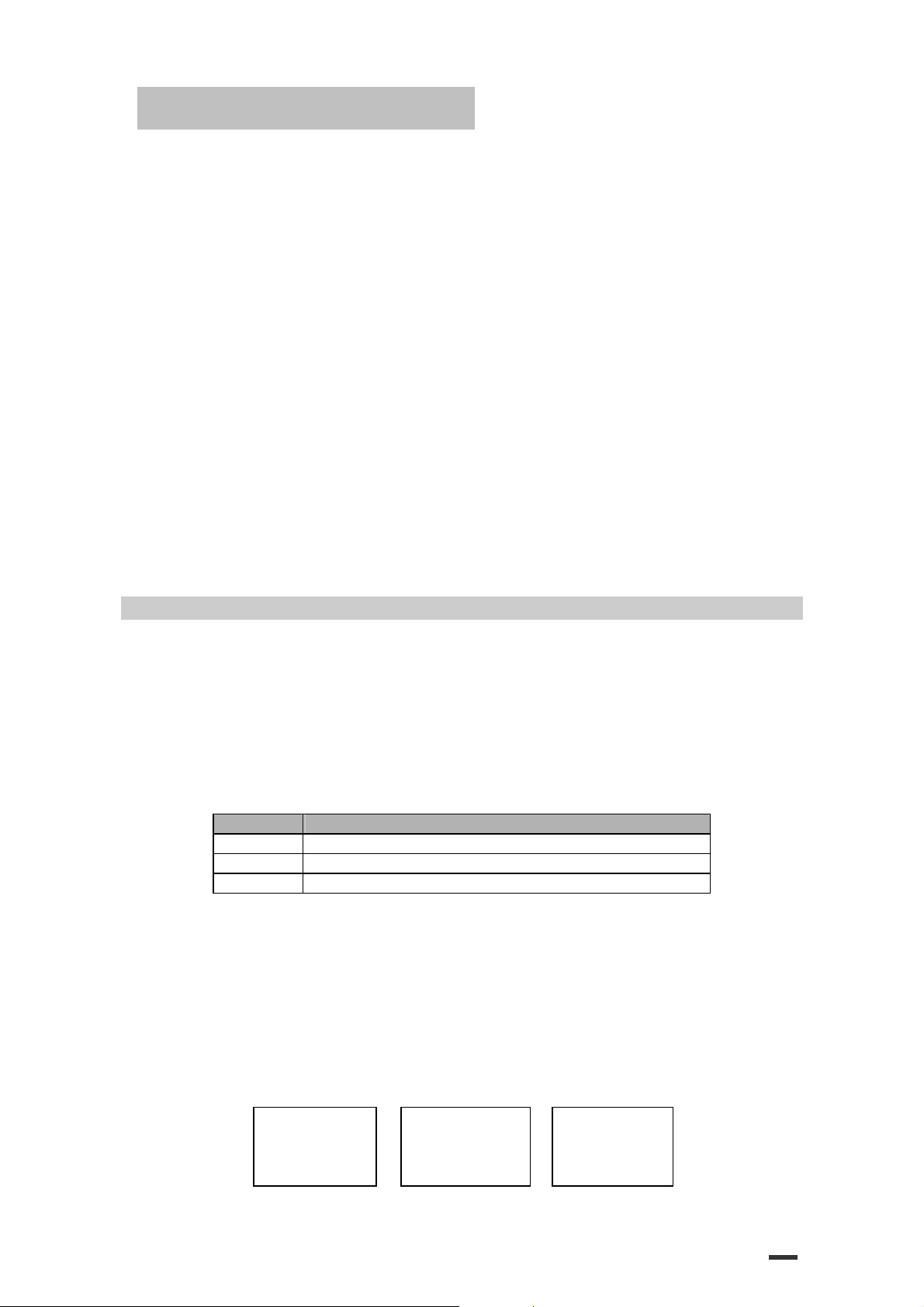
[Description] Aligns all the data in one line to the specified position
[Details] ·The command is enabled only when processed at the beginning of the line in standard mode.
[Default]
[Example]
Left justification Centering Right justification
n
selects the justification as follows:
n
Justification
0,48 Left justification
1,49 Centering
2,50 Right justification
·If this command is input in page mode, the printer performs only internal flag operation.
·This command has no effect in page mode.
·This command executes justification in the printing area.
·This command justifies the space area according to HT, ESC $ or ESC \
n
= 0
ABC
ABCD
ABCDE
is specified to the right :
n
H
x 256 =
N
n
is specified to the left (the negative direction), use the complement of 65536.
n
is specified to the left :
n
L
+
n
H
y
) is used.
n
n
x 256 = 65536 –
n.
n
x horizontal or vertical motion
n
ABC
ABCD
ABCDE
ABCD
ABCDE
25
Page 26
ESC/POS Command Manual
ESC d
n
[Name] Print and feed n lines
[Format] ASCII ESC d
Hex 1B 64
Decimal 27 100
[Range] 0≤
[Description] Prints the data in the print buffer and feeds n lines.
[Details] ·This command sets the print starting position to the beginning of the line
·This command does not affect the line spacing set by ESC 2 or ESC 3.
·The maximum paper feed amount is 1016 mm{40”}. If the paper feed amount(n x line spacing) of
[Reference] ESC 2, ESC 3
ESC t
n
[Name] Select character code table
[Format] ASCII ESC t
Hex 1B
Decimal 27 116
[Range] 0≤
[Description] Selects a page n from the character code table.
n
Page
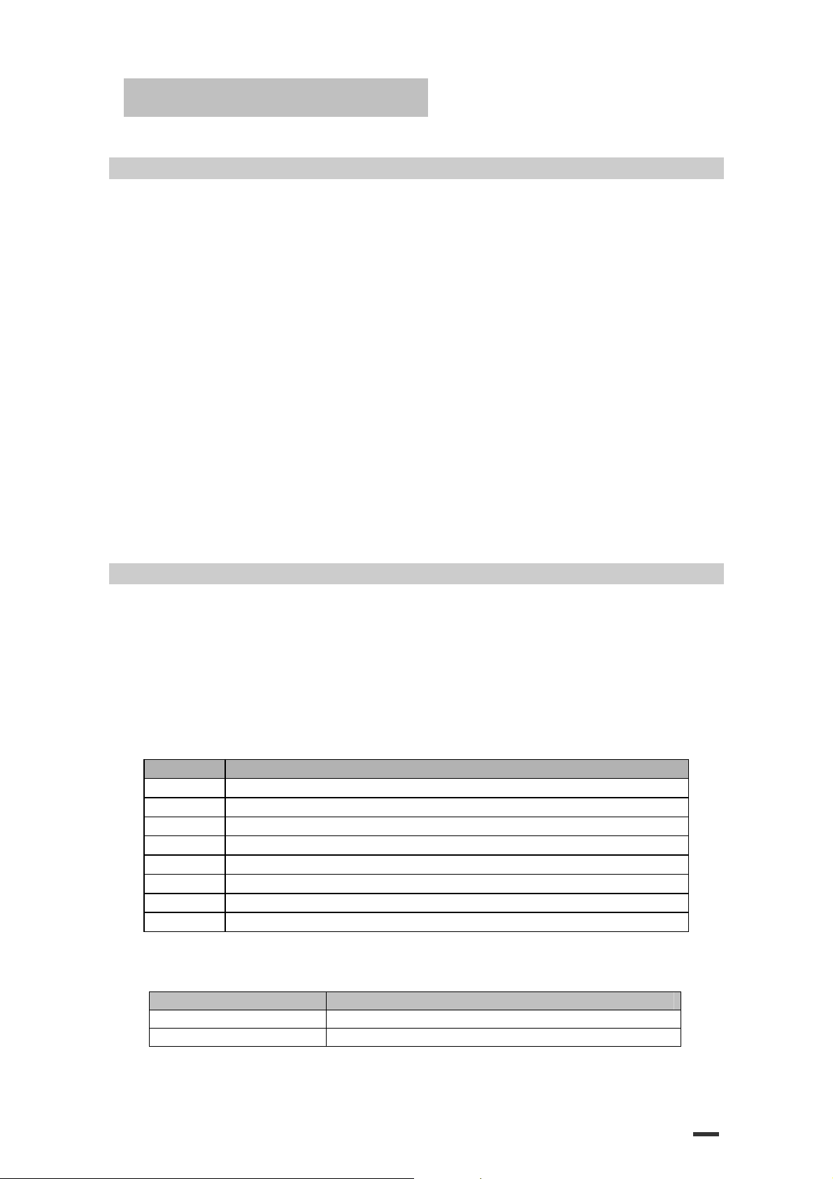
0 PC437 [U.S.A., Standard Europe]
1 Katakana
2 PC850 [Multilingual]
3 PC860 [Portuguese]
4 PC863 [Canadian-French]
5 PC865 [Nordic]
17 PC866 [Cyrillic #2]
255 Space page
[Default]
n
≤255
more than 1016 mm{40”} is specified, the printer feeds the paper only 1016 mm{40”}.
n
n
≤5, 16≤n≤26, n = 255
n
= 0
74
n
n
n
n
n
[Reference] Factory default set code page
Code page Language
CP737 Greek
CP852 Latin2
26
Page 27
ESC/POS Command Manual
CP857
CP862
CP864
CP866
CP1252
CP1253
ISO8859
ESC {
n
[Name] Turns on/off upside-down printing mode
[Format] ASCII ESC {
Hex 1B 7B
Decimal 27 123
[Range] 0 ≤ n ≤ 255
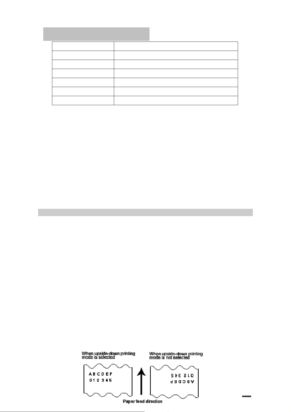
[Description] Turns upside-down printing mode on or off.
n
·When the LSB of
·When the LSB of
[Details] ·Only the lowest bit of
·This command is enabled only when processed at the beginning of a line in standard mode.
·When this command is input in page mode, the printer performs only internal flag operations.
·This command does not affect printing in page mode.
·In upside-down printing mode, the printer rotates the line to be printed by 180˚ and
then prints it.
[Default]
[Example]
n
= 0
is 0, upside-down printing mode is turned off.
n
is 1, upside-down printing mode is turned on.
n
is valid.
n
n
n
Turkish
Hebrew
Arabic
Cyrillic
Latin1(Spanish)
Greek
Latin5(Turkish)
27
Page 28

ESC/POS Command Manual
FS p
n m
[Name] Print NV bit image
[Format] ASCII FS p
Hex 1C 70
Decimal 28 112
n
[Range] 1 ≤
[Description] Prints a NV bit image n using the mode specified by m.
m Mode Vertical Dot Density Horizontal Dot Density
0, 48 Normal 180 dpi 180 dpi
1, 49 Double-width 180 dpi 90 dpi
2, 50 Double-height 90 dpi 180 dpi
3, 51 Quadruple 90 dpi 90 dpi
[dpi : dots per 25.4mm {1”}]
≤ 255
0 ≤ m ≤ 3, 48 ≤ m ≤ 51
n m
n m
n m
n
[Details] ·
is the number of the NV bit image (defined using the FS q command).
·m specifies the bit image mode.
·
NV
bit image means a bit image which is defined in a non-volatile memory by FS q and
28
Page 29

ESC/POS Command Manual
printed by FS p.
·This command is not effective when the specified NV bit image has not been defined.
·In standard mode, this command is effective only when there is no data in the print buffer.
·In page mode, the command is not effective.
·This command is not affected by print modes (emphasized, double-strike, underline,
character size, white/black reverse printing, or 90° rotated characters, etc.),
except upside-down printing mode.
·If the printing area width set by GS L and GS W for the NV bit image is
less than one vertical line the following processing is performed only on
the line in question. However, in NV bit image mode, one vertical line
means 1 dot in normal mode (m=0,48) and in double-height mode
(m=2,50), and it means 2 dots in double-width mode (m=1,49) and in
quadruple mode (m=3,51).
The printing area width is extended to the right in NV bit image mode ①
If the printing area width cannot be extended by one line vertically, ②
the left margin is reduced to accommodate one line vertically.
·If the downloaded bit-image to be printed exceeds one line, the excess data is not printed.
·This command feeds dots (for the height n of the NV bit-image) in normal and
double-width modes, and(for the height
and quadruple modes, regardless of the line spacing specified by ESC 2 or ESC 3.
·After printing the bit image, this command sets the print position to the beginning of the line
and processes the data that follows as normal data.
[References] ESC *, FS q, GS/, GS v 0
FS q n [
[Name] Define NV bit image
[Format] ASCII FS q n
Hex 1C 71 n
[Range] 1 ≤
Total defined data area = 2M bits (256K bytes)
xL xH yL yH d1...dk
Decimal 28 113 n
n
≤ 255
0 ≤ xL ≤ 255
0 ≤ xH ≤ 3 (when 1 ≤ (xL + xH × 256) ≤ 1023)
0 ≤ yL ≤ 255
0 ≤ yL ≤ 1 (when 1 ≤ (yL + yH × 256) ≤ 288)
0 ≤ d ≤ 255
k = (xL + xH × 256) × (yL + yH × 256) × 8
] 1...[
xL xH yL yH d1...dk]n
[xL xH yL yH d1...dk]1...[xL xH yL yH d1...dk]n
[xL xH yL yH d1...dk]1...[xL xH yL yH d1...dk]n
n
x 2 of the NV bit-image) in double-height
[xL xH yL yH d1...dk]1...[xL xH yL yH d1...dk]n
29
Page 30

ESC/POS Command Manual
[Description] Define the NV bit image specified by
n
.
[Details] ·
n
specifies the number of the defined NV bit image.
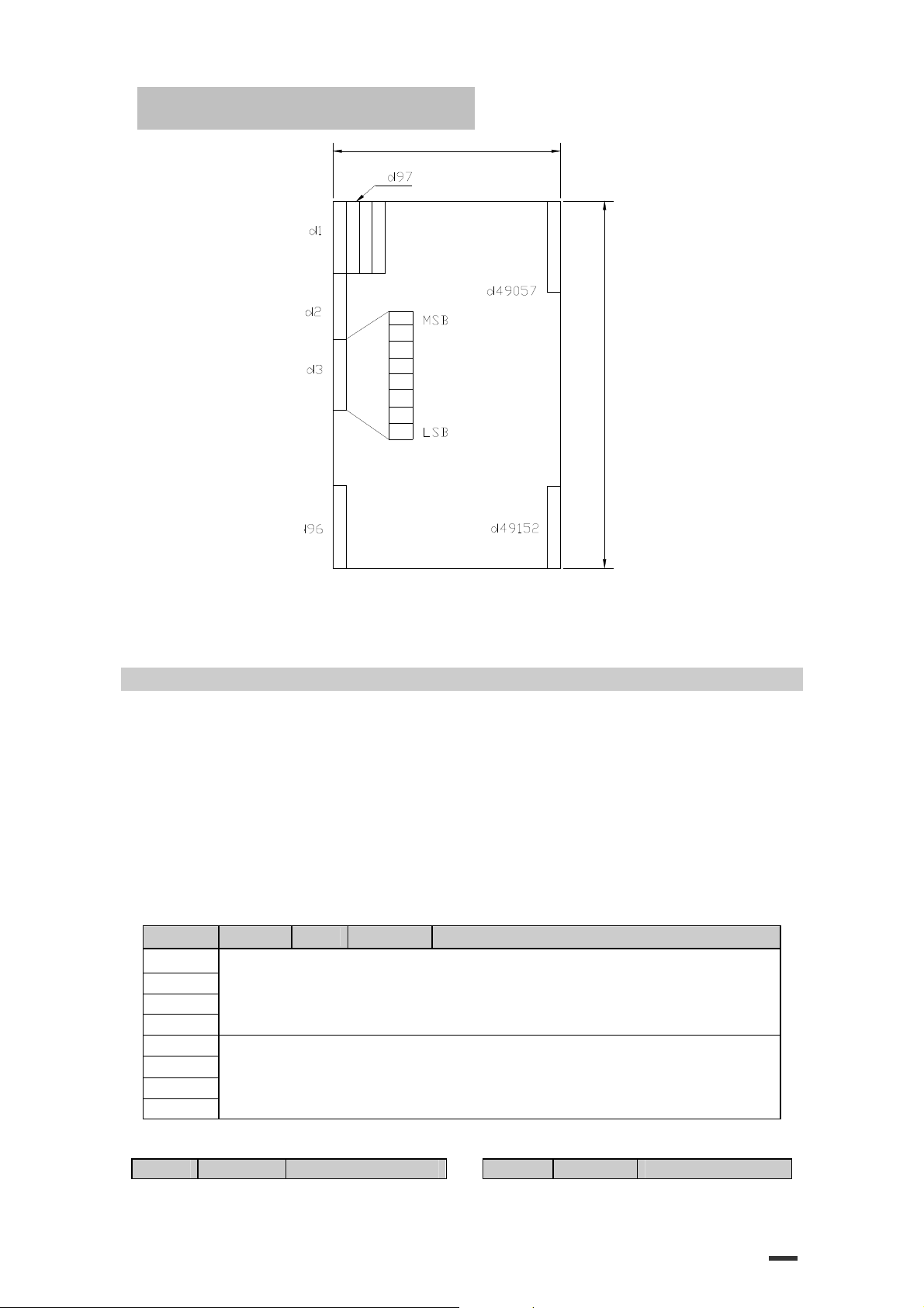
·xL, xH specifies (xL + xH × 256) × 8 dots in the horizontal direction for
the NV bit image you are defining.
·yL, yH specifies (yL + yH × 256) × 8 dots in the vertical direction for the NV
bit image you are defining.
·This command cancels all NV bit image that have already been defined by this command.
The printer can not redefine only one of several data definitions previously defined.
In this case, all data needs to be sent again.
·From the beginning of the processing of this command till the finish of
hardware reset, mechanical operations (including initializing the position
of the printer head when the cover is open, paper feeding by using the
FEED button, etc.) cannot be performed.
·During processing this command, the printer is in BUSY when writing the
data to the NV user memory and stops receiving data. Therefore it is
prohibited to transmit the data including the real-time commands during
the execution of this command.
·NV bit image means a bit image which is defined in a non-volatile memory
by FS q and printed by FS p.
·In standard mode, this command is effective only when processed at the
beginning of the line.
·In page mode, this command is not effective.
·This command is effective when 7 bytes <FS-yH> is processed as a normal value.
·When the amount of the data exceeds the capacity left in the range
defined by xL, xH, yL, yH, the printer processes xL, xH, yL, yH out of the defined range.
·In the first group of NV bit image, when any of the parameters xL, xH, yL,
yH, is out of the definition range, the command is disabled.
·In groups of NV bit image other than the first one, when the printer
processes xL, xH yL, yH out of the defined range, it stops processing this
command and stars writing into the NV images. At this time, NV bit image
that haven’t been defined are disabled (undefined), but any NV bit
images before that are enabled.
·The d indicates the definition data. In data (d) a 1 bit specifies a dot to be
printed and a 0 bit specifies a dot not to be printed.
·This command defines n as the number of a NV image. Number rise in
order from NV bit image 01H. Therefore, the first data group [xL xH yL yH
30
Page 31

ESC/POS Command Manual
d1...dk] is NV bit image 01H, and the last data group [xL xH yL yH
d1...dk] is NV bit image n. The total agrees with the number of NV bit
images specified by command FS p.
·A definition data of a NV bit image consists of [xL xH vL vH d1...dk].
Therefore, when only one NV bit image is defined n=1, the printer
processes a data group [xL xH yL yH d1...dk] once. The printer uses
([data:(xL + xH ×256) × (yL + yH × 256) × 8] + [header:4]) bytes of NV memory.
·The definition area in this printer is a maximum of 2M bits (256K bytes).
This command can define several NV bit image, but cannot define a bit
image data whose total capacity [bit image data + header] exceeds 2M bytes (256K bytes).
·The printer is busy immediately before writing into NV memory, regardless
of the setting of DIP switch 2-1.
·The printer does not transmit ASB status and perform status detection
during processing of the command even when ASB is specified.
·When this command is received during macro definition, the printer ends
macro definition, and begins performing this command.
·Once a NV bit image is defined, it not erased by performing ESC @, reset, and power off.
·This command performs only definition of a NV bit image and does not
perform printing. Printing of the NV bit image is performed by the FS q command.
[Notes] ·Frequent write command execution may cause damage the NV memory.
Therefore, it is recommended to write the NV memory 10 times or less a day.
·The printer performs a hardware reset after the procedure to place the
image into the NV memory. Therefore, user-defined characters,
downloaded bit image, and macros should be defined only after
completing this command. The printer clears the receive and print buffers
and resets the mode to the mode that was in effect at power on. At this time,
DIP switch setting are checked again.
n is the number of the NV bit
[Reference] FS p
x
[Example] When
L = 64, xH = 0, yL = 96, yH = 0
31
Page 32
ESC/POS Command Manual
(
y
L
+
y
H
x
2
5
6
)
x
8
d
o
t
s
=
7
6
8
d
o
t
s
(xL + xH x 256) x 8 dots = 512 dots
GS ! n
[Name] Select character size
[Format] ASCII GS !
Hex 1D 21
Decimal 29 33
[Range] 0 ≤
n
≤ 255
(1 ≤ vertical number of times ≤ 8, 1 ≤ horizontal number of times ≤ 8)
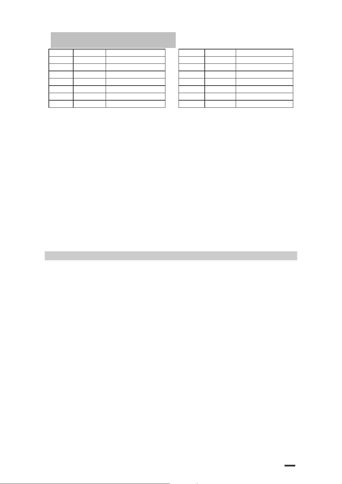
[Description] Selects the character height using bits 0 to 3 and selects the character width using bits 4 to 7,
as follows:
Bit Off/On Hex Decimal Function
0
1
2
3
4
5
6
7
Table 1. Character Width Selection. Table 2. Character Height Selection.
Hex Decimal Width Hex Decimal Width
Character height selection. See Table 2.
Character width selection. See Table 1.
n
n
n
32
Page 33
ESC/POS Command Manual
00 0 1 (normal) 00 0 1 (normal)
10 16 2 (double-width) 01 1 2 (double-height)
20 32 3 02 2 3
30 48 4 03 3 4
40 64 5 04 4 5
50 80 6 05 5 6
60 96 7 06 6 7
70 112 8 07 7 8
[Details] ·This command is effective for all characters (except for HRI characters).
·If n is outside of the defined range, this command is ignored.
·In standard mode, the vertical direction is the paper feed direction, and
the horizontal direction is perpendicular to the paper feed direction.
However, when character orientation changes in 90° clockwise-rotation mode, the
relationship between vertical and horizontal directions is reversed.
·In page mode, vertical and horizontal directions are based on the character orientation.
·When characters are enlarged with different sizes on one line, all the characters on the line are
aligned at the baseline.
·The ESC ! command can also turn double-width and double- height modes on or off.
However, the setting of the last received command is effective.
n
[Default]
[Reference] ESC !
GS $
nL nH
[Name] Set absolute vertical print position in page made
[Format] ASCII GS $
Hex 1D 24
Decimal 29 36
[Range] 0 ≤
[Description] ·Sets the absolute vertical print starting position for buffer character data in page mode.
·The horizontal starting buffer position does not move.
·The reference starting position is that specified by ESC T.
When the starting position is set to the upper left or lower right, this ①
When the starting position is set to the upper right or lower left, this ②
command sets the absolute position in the horizontal direction.
[Reference] ESC $, ESC T, ESC W, ESC \, GS \
= 0
nL nH
nL nH
nL nH
nL
≤ 255
, 0 ≤ nH
≤ 255
·This command sets the absolute print position to [ (
unit)] inches.
nL + nH
·If the [ (
specified printing area, this command is ignored.
·This command operates as follows, depending on the starting position of the printing area
specified by ESC T:
× 256) × (vertical or horizontal motion unit)] exceeds the
command sets the absolute position in the vertical direction.
nL + nH
×256) × (vertical or horizontal motion
33
Page 34

ESC/POS Command Manual
GS ∗ x y
[Name] Define downloaded bit image
[Format] ASCII GS ∗
Hex 1D 2A
Decimal 29 42
[Range] 1 ≤
1 ≤ y ≤ 48
0 ≤
[Description] Defines a downloaded bit image with the number of dots specified by x and y.
·
·
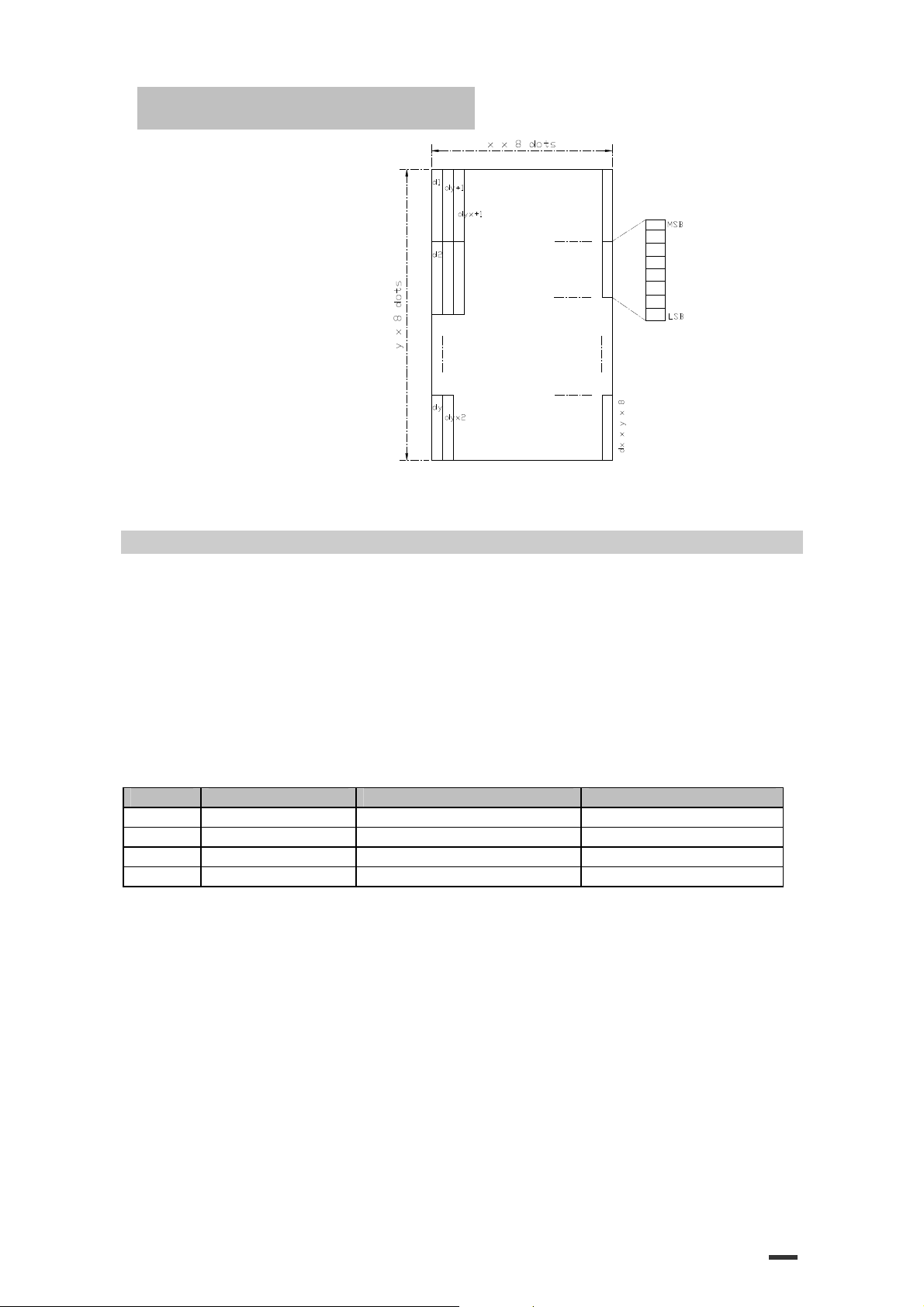
[Details] ·The number of dots in the horizontal direction is x x 8, in the vertical
d1...d
(x × y × 8)
x
x
x
x
≤ 255
x
x y ≤ 1536
d
≤ 255
x
indicates the number of dots in the horizontal direction.
y
indicates he number of dots in the vertical direction.
direction it is
x
x y is out of the specified range, this command is disabled.
·If
·The d indicates bit-image data. Data
·The downloaded bit image definition is cleared when:
① ESC@ is executed.
② ESC & is executed.
③ FS q is executed.
④ Printer is reset or the power is turned off.
·The following figure shows the relationship between the downloaded bit
image and the printed data.
y
x 8.
(d)
y
y
y
specifies a bit printed to 1 and not printed to 0.
d1
d1
d1
… d (x x y x 8)
… d (x x y x 8)
… d (x x y x 8)
34
Page 35
ESC/POS Command Manual
[Reference] GS \
GS /
m
[Name] Print down-loaded bit image
[Format] ASCII GS /
Hex 1D 2F
Decimal 29 47
[Range] 0 ≤
[Description] Prints a downloaded bit image using the mode specified by m.
m selects a mode from the table below:
m
0, 48 Normal 180 DPI 180 DPI
1, 49 Double-width 180 DPI 90 DPI
2, 50 Double-height 90 DPI 180 DPI
3, 51 Quadruple 90DPI 90 DPI
[dpi : dots per 25.4 mm {1”}]
[Details] ·This command is ignored if a downloaded bit image has not been defined.
m
≤ 3,48 ≤ m ≤ 51
Mode Vertical Dot Density Horizontal Dot Density
·In standard mode, this command is effective only when the on data exists
in the print buffer.
·This command is not affected by print modes (emphasized, double-strike,
underline, or character size, white/black reverse printing), except for
upside down mode.
·If the downloaded bit-image to be printed exceeds the printable area, the
excess data is not printed.
·If the printing area width set by GS L and GS W is less than one line
vertical, the following processing is performed only on the line in
question:
① The printing area width is extended to the right up to one line in
vertical. In this case, printing does not exceed the printable area.
m
m
m
35
Page 36

ESC/POS Command Manual
② If the printing area width cannot be extended by one line in vertical,
the left margin is reduced to accommodate one line in vertical.
[Reference] GS ∗
GS B n
[Name] Turn white/black reverse printing mode
n
[Format] ASCII GS B
Hex 1D 42
Decimal 29 66
[Range] 0 ≤
[Description] Turns on or off white/black reverse printing mode.
[Details] ·Only the LSB of n is effective.
·This command does not affect the space between lines.
·White/black reverse mode has a higher priority than underline mode. Even
[Default]
n
≤ 255
n
·When the LSB of
·When the LSB of
·This command is available for built-in characters and user-defined characters.
·When white/black reverse printing mode is on, it also applied to
character spacing set by ESC SP.
·This command does not affect bit image, user-defined bit image, bar
code, HRI characters, and spacing skipped by HT, ESC $, and ESC\.
if underline mode is on, it is disabled (but not canceled) when
white/black reverse mode is selected.
n
= 0
is 0, white/black reverse printing mode is turned off.
n
is 1, white/black reverse printing mode is turned on.
GS H n
[Name] Select printing position of HRI characters
n
[Format] ASCII GS H
Hex 1D 48
Decimal 29 72
[Range] 0 ≤
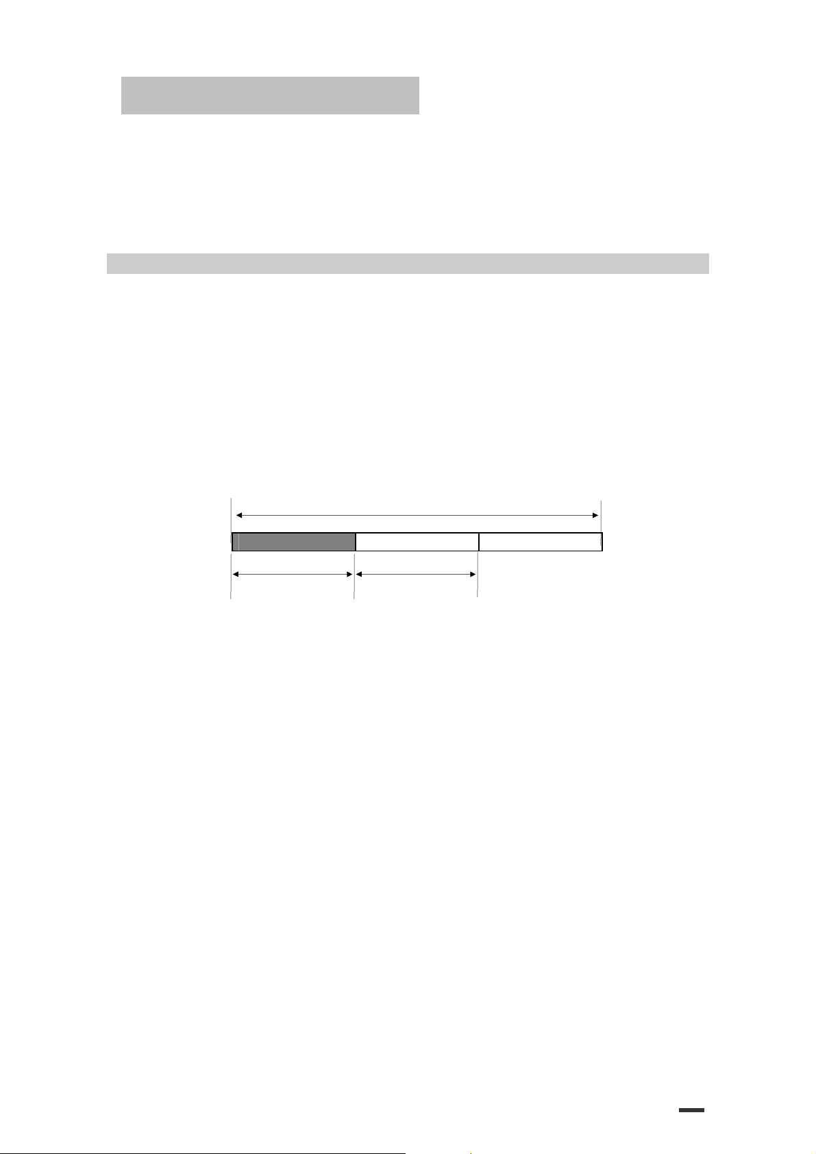
[Description] Selects the printing position of HRI characters when printing a bar code.
n
≤ 3, 48 ≤ n ≤ 51
n
selects the printing position as follows:
n
0, 48 Not printed
1, 49 Above the bar code
2, 50 Below the bar code
3, 51 Both above and below the bar code
n
n
n
n
Printing position
36
Page 37
ESC/POS Command Manual
[Details] ·HRI means Human Readable Interpretation.
·HRI characters are printed using the font specified by GS f.
n
[Default]
[Reference] GS f, GS k
GS L
nL nH
[Name] Set left margin
[Format] ASCII GS L
Hex 1D 4C
Decimal 29 76
[Range] 0 ≤
0 ≤
[Description] Sets the left margin using nL and nH.
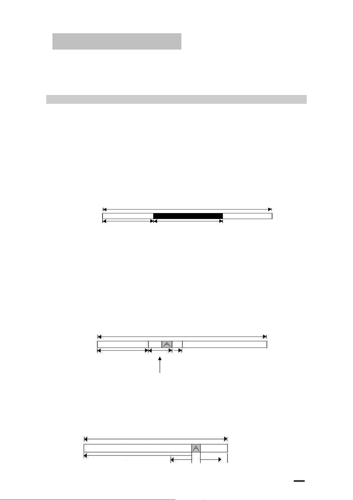
Printable area
[Details] ·This command is effective only of the beginning of a line.
[Default]
[Reference] GS W
= 0
nL nH
nL nH
nL nH
nL
≤ 255
nH
≤ 255
·The left margin is set to [(
Left margin Printing width
·If this command is input in page made, the printer performs only internal flag operations.
·This command does not affect printing in page made.
·If the setting exceeds the printable area, the maximum value of the printable area is used.
·The horizontal motion unit (x) is used for calculating the left margin.
The calculated result is truncated to the minimum value of the mechanical pitch.
nL
= 0, nH = 0
nL + nH
× 256) × (horizontal motion unit)] inches.
37
Page 38
ESC/POS Command Manual
GS W
nL nH
[Name] Set printing area width
nL nH
[Format] ASCII GS W
Hex 1D 57
Decimal 29 87
[Range] 0 ≤ nL ≤ 255
0 ≤
nH
≤ 255
[Description] Sets the printing area width to the area specified by nL and
·The printing area width is set to [(
nL
nL nH
nL nH
+ nH x 256) x horizontal motion unit]].
Printable area
nH.
Left margin Printing area width
[Details] ·This command is effective only processed at the beginning of the line.
·In page mode, the printer performs only internal flag operations.
·This command does not affect printing in page mode.
·If the [left margin + printing area width] exceeds the printable area, [printable area width - left
margin] is used.
·The horizontal motion unit (x) is used for calculating the printing area width. The calculated result
is truncated to the minimum value of the mechanical pitch.
·If the width set for the printing area is less than the width of one character, when the character
data is developed, the following processing is performed:
① The printing area width is extended to the right to accommodate one character.
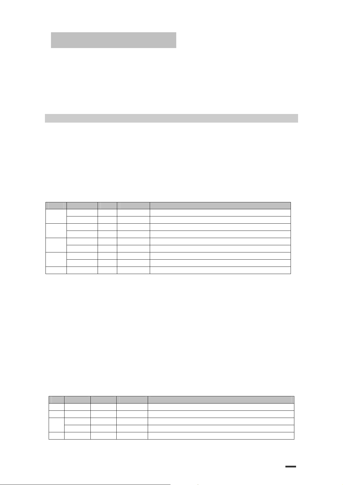
Printable area
Left margin Extended to right
Printing area width set by nL and nH
② f the printing area width cannot be extended sufficiently, the left margin is reduced
to accommodate one character
Printable area
38
Page 39

ESC/POS Command Manual
Extended to right①
Left margin Reduce left margin ②
If the printing area width cannot be extended sufficiently, the right space is③ reduced.
·If the width set for the printing area is less than one line in vertical, the following processing is
performed only on the line in question when data other than character data (e.g., bit image,
user-defined bit image) is developed:
① The printing area width is extended to the right to accommodate one line in vertical
for the bit image within the printable area.
② If the printing area width cannot be extended sufficiently, the left margin is reduced
to accommodate one line in vertical.
·The commands which set the printing area width for bit image printing and its minimum widths
are as follows:
·Bit image (ESC *) :
Single density mode = 2 dots
Double density mode = 1 dot
·Downloaded bit image (GS /):
Double width mode or Quadruple mode = 2 dots
Normal mode or Double-height mode = 1 dot
·NV bit image (FS p) :
Double width mode or Quadruple mode = 2 dots
Normal mode or Double-height mode = 1 dot
·Raster bit image (GS v 0) :
Double width mode or Quadruple mode = 2 dots
Normal mode or Double-height mode = 1 dot
nL
= 0,
nH
[Default]
[Reference] GS L
GS \
[Name] Set relative vertical print position in page mode
[Format] ASCII GS \
Decimal 29 92
[Range] 0 ≤
[Description] Sets the relative vertical print starting position from the current position in page mode.
[Details] ·This command is ignored unless page mode is selected.
nL nH
Hex 1D 5C
0 ≤ nH ≤ 255
·This command sets the distance from the current position to [( nL + nH x 256) vertical or
·When pitch N is specified to the movement downward:
= 2
nL nH
nL nH
nL nH
nL
≤ 255
horizontal motion unit] inches.
nL + nH
x 256 = N
When pitch N is specified to the movement upward (the negative direction), use the
complement of 65536.
When pitch N is specified to the movement upward:
nL + nH
x 256 = 65536 – N
39
Page 40
ESC/POS Command Manual
·Any setting that exceeds the specified printing area is ignored.
·This command function as follows, depending on the print starting position set by ESC T:
① When the starting position is set to the upper left or lower right of the printing, the
y
vertical motion unit (
② When the starting position is set to the upper right or lower left of the printing area, the
horizontal motion unit (x) is used.
[Reference] ESC $, ESC T, ESC W, ESC \, GS $
GS a n
[Name] Enable/Disable Automatic Status Back (ASB)
[Format] ASCII GS a
Hex 1D 61
Decimal 29 97
[Range] 0 ≤ n ≤ 255
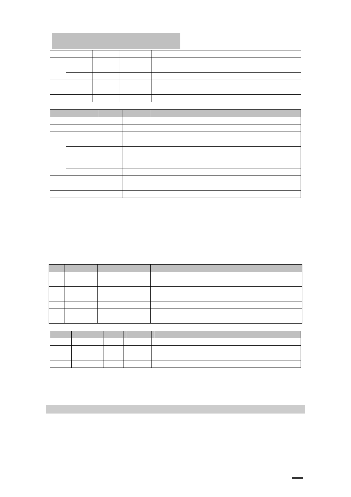
[Description] Enables or disables ASB and specifies the status items to include, using n as follows:
Bit Off/ On Hex Decimal Status for ASB
0
1
2
3
4–7 - - - Undefined.
[Details] ·If any of the status items in the table above are enabled, the printer
First byte (printer information)
Bit Off/On Hex Decimal Status for ASB
0 Off 00 0 Not used. Fixed to Off
1 Off 00 0 Not used. Fixed to Off
2
3 Off 00 0 On-line
Off 00 0 .
On 01 1
Off 00 0 On-line/off-line status disabled.
On 02 2 On-line/off-line status enabled
Off 00 0 Error status disabled
On 04 4 Error status enabled.
Off 00 0 Paper roll sensor status disabled.
On 08 8 Paper roll sensor status enabled.
transmits the status when this command is executed. The printer automatically transmits
the status whenever the enabled status item changes. The disabled status items may
change, in this case, because each status transmission represents the current status.
·If all status items are disabled, the ASB function is also disabled.
·If the ASB is enabled as a default, the printer transmits the status when the printer data
reception and transmission is possible at the first time from when the printer is turned on.
·The following four status bytes are transmitted without confirming whether the host is ready to
receive data. The four status bytes must be consecutive, except for the XOFF code.
·Since this command is executed after the data is processed in the receive
buffer, there may be a time lag between data reception and status transmission.
·When using DLE EOT, GS I , or GS r, the status transmitted by these
commands and ASB status must be differentiated.
·The status to be transmitted are as follows:
Off 00 0
On 04 4
) is used.
n
n
n
40
Page 41
ESC/POS Command Manual
On 08 8 Off-line
4 On 10 16 Not used. Fixed to On
5
6
7 Off 00 0 Not used. Fixed to Off
Second byte (printer information)
Bit Off / On Hex Decimal Status for ASB
0 - - - Undefined.
1 - - - Undefined.
2 - - - Undefined.
3
4 Off 00 0 Not used. Fixed to Off
5
6
7 Off 00 0 Not used. Fixed to Off
Bit 3: If these errors occur due to paper jams or the like, it is possible to recover by
Bit 6: When printing is stopped due to high print head temperature until the print head
Third byte (paper sensor information)
Bit Off / On Hex Decimal Status for ASB
0,1
2,3
4 Off 00 0 Not used. Fixed to Off
5,6 - - - Undefined
7 Off 00 0 Not used. Fixed to Off
Fourth byte (paper sensor information)
Bit Off / On Hex Decimal Status for ASB
0-3 - - - Undefined
5,6 - - - Undefined
[Default] n = 0.
[Reference] DLE EOT, GS r
GS f n
[Name] Select font for Human Readable Interpretation (HRI)characters
[Format] ASCII GS f
Decimal 29 102 n
Off 00 0 Cover is closed
On 20 32 Cover is open
Off 00 0 Paper is not being fed by using the PAPER FEED button
On 40 64 Paper is being fed by using the PAPER FEED button
Off 00 0
On 08 8
Off 00 0 No unrecoverable error
On 20 32 Unrecoverable error occurred
Off 00 0 No automatically recoverable error
On 40 64 Automatically recoverable error occurred
correcting the cause of the error and executing DLE ENQ
n
(1 ≤ n ≤ 2). If an error due to a circuit failure (e.g.
wire break) occurs, it is impossible to recover.
temperature drops sufficiently or when the paper roll cover is open during printing,
bit 6 is On.
Off 00 0
On 03 3
Off 00 0 Paper roll end sensor: paper present
On 0C 12 Paper roll end sensor: paper not present
4 Off 00 0 Not used. Fixed to Off
7 Off 00 0 Not used. Fixed to Off.
n
n
Hex 1D 66
41
Page 42

ESC/POS Command Manual
n
[Range]
[Description] selects a font for the HRI characters used when printing a bar code.
[Details] ·HRI means Human Readable Interpretation.
[Default]
[Reference] GS H, GS k
GS h n
[Name] Select bar code height
[Format] ASCII GS h
Hex 1D 6B
Decimal 29 104 n
[Range] 1 ≤
[Description] Select the height of the bar code.
[Default]
[Reference] GS k
GS k m d1…dk NUL GS k m n d1…dn① ②
[Name] Print bar code
= 0, 1, 48, 49
n
selects the font from the following table:
n
Font
0, 48 Font A (12 x 24)
1, 49 Font B (9 x 17)
·HRI characters are printed of the position specified by GS H.
n
= 0
n
n
n
≤ 255
n
specifies the number of dots in the vertical direction.
n
= 162
42
Page 43
ESC/POS Command Manual
m
d1…dk
d1…dn
00
0
[Format] ASCII GS k ①
Hex 1D 6B
Decimal 29 107
ASCII GS k ②
Hex 1D 6B
Decimal 29 107
m
m
d1…dn
m n d1…dn
m n d1…dn
m n d1…dn
[Range] 0 ① ≤
65 ② ≤
m
≤ 6( k and d depends on the code system used)
m
≤ 73 n and d depends on the code system used)
[Description] Selects a bar code system and prints the bar code.
m
selects a bar code system as follows:
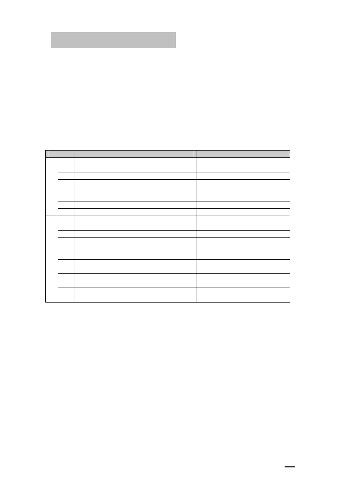
m
0 UPC – A 11 ≤ k ≤ 12 48 ≤ d ≤ 57
1 UPC – E 11 ≤ k ≤ 12 48 ≤ d ≤ 57
2 EAN13 12 ≤ k ≤ 13 48 ≤ d ≤ 57
3 EAN8 7 ≤ k ≤ 8 48 ≤ d ≤ 57
①
4 CODE39 1 ≤ k 48 ≤ d ≤ 57, 65 ≤ d ≤ 90,
5 ITF 1 ≤ k (even number) 48 ≤ d ≤ 57
6 CODABAR 1 ≤ k 48 ≤ d ≤ 57, 65 ≤ d ≤ 68, 36,43,45,46,47,58
65 UPC – A 11 ≤ n ≤ 12 48 ≤ d ≤ 57
66 UPC – E 11 ≤ n ≤ 12 48 ≤ d ≤ 57
67 EAN13 12 ≤ n ≤ 13 48 ≤ d ≤ 57
68 EAN8 7 ≤ n ≤ 8 48 ≤ d ≤ 57
69 CODE39 1 ≤ n ≤ 255 48 ≤ d ≤ 57, 65 ≤ d ≤ 90,
②
70 ITF 1 ≤ n ≤ 255
71 CODABAR 1 ≤ n ≤ 255 48 ≤ d ≤ 57, 65 ≤ d ≤ 68,
72 CODE93 1 ≤ n ≤ 255 0 ≤ d ≤ 127
73
Bar Code System Number of Character Remarks
32,36,37,43,45,46,47
32,36,37,43,45,46,47
48 ≤ d ≤ 57
(even number)
36,43,45,46,47,58
CODE128 2 ≤ n ≤ 255 0 ≤ d ≤ 127
[Details for ] ·This command ends with① a NUL code.
·When the bar code system used is UPC-A or UPC-E, the printer prints the bar code data
after receiving 12 bytes bar code data and processes the following data as normal data.
·When the bar code system used is JAN 13, the printer prints the bar code after receiving 13
bytes bar code data and processes the following date as normal data.
·When the bar code system used is JAN 8, the printer prints the bar code after receiving 8
bytes bar code data and processes the following data as normal data.
·The number of data for ITF bar code must be even numbers. When
an odd number of data is input, the printer ignores the last received
data.
n
[Details for ] ·②
indicates the number of bar code data, and the printer processes n bytes from the next character
data as bar code data.
·If n is outside of the specified range the printer stops command processing and processes the
following data as normal data.
[Details in standard made]
d
is outside of the specified range, the printer only feeds paper and process the following
·If
data as normal data.
·If the horizontal size exceeds printing area, the printer only feeds the paper.
·This command feeds as much paper as is required to print the bar code, regardless of the line
NUL
43
Page 44
ESC/POS Command Manual
spacing specified by ESC 2 or ESC 3.
·This command is enabled only when on data exists in the print buffer.
When data exists in the print butter, the printer processes the data following m as normal data.
·After printing bar code, this command sets the print position to the beginning of the line.
·This command is not affected by print modes (emphasized, double-strike, underline,
character size, white/black reverse printing, or 90˚ rotated character, etc), except for upsidedown printing mode.
[Details in page made]
·This command develops bar coed data in the print buffer, but does not print it. After
processing bar cod data, this command moves the print position to the right side dot of the bar
code.
·If d is out of the specified rang, the printer stops command processing and processes the
following data as normal data. In this case, the data butter position does not change.
·If bar code width exceeds the printing area, the printer does not print the bar code but moves
the data buffer position to the left side out of the printing area.
·Refer to Figure 3.12.3 for bar code data buffer position.
When CODE93 (m=72) is used :
·The printer prints an HRI character (□)as start character at the
beginning of the HRI character string.
·The printer prints an HRI character(□)as a stop character at the end of
the HRI character string.
·The printer HRI characters (■+an alphabetic character) as a control
character(<00>H to <1F>H and <7F>H):
Control character Control character
ASCⅡ Hex Decimal
NUL 00 0 ■U DLE 10 16 ■P
SOH 01 1 ■A DC1 11 17 ■Q
STX 02 2 ■B DC2 12 18 ■R
ETX 03 3 ■C DC3 13 19 ■S
EOT 04 4 ■D DC4 14 20 ■T
ENQ 05 5 ■E NAK 15 21 ■U
ACK 06 6 ■F SYN 16 22 ■V
BEL 07 7 ■G ETB 17 23 ■W
BS 08 8 ■H CAN 18 24 ■X
HT 09 9 ■I EM 19 25 ■Y
LF 0A 10 ■J SUB 1A 26 ■Z
VT 0B 11 ■K ESC 1B 27 ■A
FF 0C 12 ■L FS 1C 28 ■B
CR 0D 13 ■M GS 1D 29 ■C
SO 0E 14 ■N RS 1E 30 ■D
SI 0F 15 ■0 US 1F 31 ■E
DEL 7F 127 ■T
[Example] Printing GS k 72 7 67 111 100 101 13 57 51
HRI character
ASCⅡ Hex Decimal
HRI character
44
Page 45
ESC/POS Command Manual
When CODE 128 (m = 73) is used:
·Refer to Appendix J for the information of the CODE 128 bar code and is
code table.
·When using the CODE 128 in this printer, take the following points into
account for data transmission:
① The top of the bar code data string must be code set selection
character (any of CODE A, CODE B or CODE C) which selects the first code set.
② Special characters are defined by combining two characters
“{“ and one character. The ASC character “{“ is defined by transmitting “{“ twice Ⅱ
consecutively.
Specific character
SHIFT {S 7B,53 123,83
CODE A {A 7B,41 123,65
CODE B {B 7B,42 123,66
CODE C {C 7B,43 123,67
FNC1 {1 7B,31 123,49
FNC2 {2 7B,32 123,50
FNC3 {3 7B,33 123,51
FNC4 {4 7B,34 123,52
“{“ {{ 7B,7B 123,123
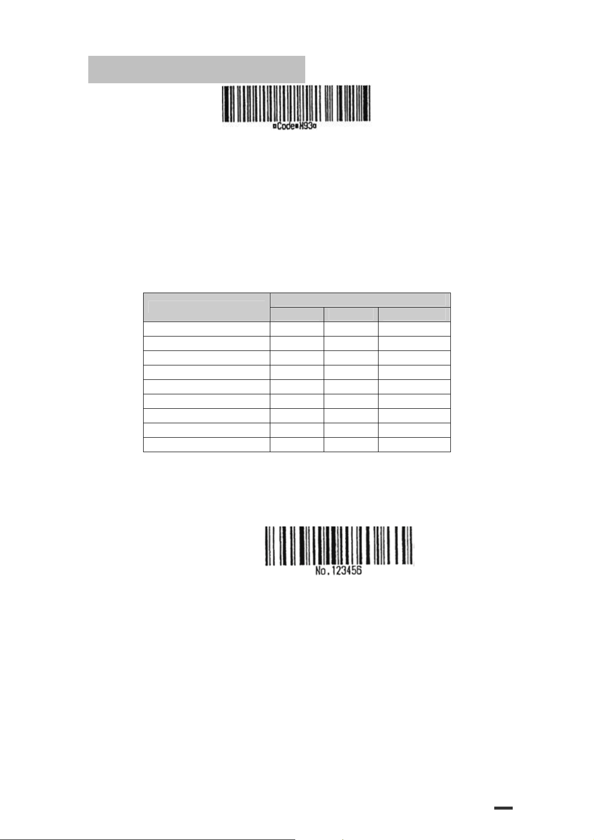
[Example] Example data for printing “No. 123456”
In this example, the printer first prints “No.” using CODE B, then prints
the following numbers using CODE C.
GS k 73 10 123 66 78 111 46 123 67 12 34 56
ASCⅡ Hex Decimal
Transmit data
·If the top of the bar code data is not the code set selection character, the
printer stops command processing and processes the following data as
normal data.
·If combination of “{“and the following character does not apply any
special character, the printer stops command processing and processes
the following data as normal data.
·If the printer receives characters that cannot be used in the special code
set, the printer stops command processing and processes the following
data as normal data.
·The printer does not print HRI characters that correspond to the shift
characters or code set selection characters.
·HRI character for the function character is space.
45
Page 46
ESC/POS Command Manual
·HRI characters for the control character (<00>H to <1F>H and <7F>H)are
space.
<Others> Be sure to keep spaces on both right and left sides of a bar code.
(Spaces are different depending on the types of the bar code.)
[Reference] GS H, GS f, GS h, GS w
GS r n
[Name] Transmit status
[Format] ASCII GS r
Hex 1D 72
Decimal 29 114 n
[Range] n=1, 2, 49, 50
[Description] Transmits the status specified by n as follows:
n
Function
1,49 Transmits paper sensor status
2,50
[Details] ·When using a serial interface
·When DTR/DSR control is selected, the printer transmits only 1 byte after confirming the host
is ready to receive data (DSR signal is SPACE). If the host computer is not ready to receive
data (DSR signal is MARK), the printer waits until the host is ready.
When XON/XOFF control is selected, the printer transmits only 1 byte without confirming the
condition of the DSR signal.
·This command is executed when the data in the receive buffer is developed. Therefore, there may
be a time lag between receiving this command and transmitting the status, depending on
the receive buffer status.
·When Auto Status Back (ASB) is enabled using GS a, the status transmitted by GS r and the
ASB status must be differentiated using the table in Appendix G.
·The status types to be transmitted are shown below:
Paper sensor status ( n = 1, 49):
Bit Off / On Hex Decimal Status for ASB
0,1
2,3
4 Off 00 0 Not used. Fixed to Off.
5,6 - - - Undefined.
7 Off 00 0 Not used. Fixed to Off.
Bits 2 and 3: When the paper end sensor detects a paper end, the printer goes off-line and does not execute
[Reference] DLE EOT, GS a
Off 00 0
On 03 3
Off 00 0 Paper roll end sensor: paper adequate.
On (0C) (12) Paper roll end sensor: paper near end.
this command. Therefore, bits 2 and 3 do not transmit the status of paper end.
GS v 0 m xL xH yL yH d1....dk
[Name] Print raster bit image
n
n
46
Page 47
ESC/POS Command Manual
[Format] ASCII GS v 0 m xL xH yL yH d1...dk
Hex 1D 76 30
Decimal 29 118 48 m xL xH yL yH d1...dk
[Range] 0 ≤ m ≤ 3, 48 ≤ m ≤ 51
0 ≤ xL ≤ 255
0 ≤ xH ≤ 255
0 ≤ yL ≤ 255
0 ≤ yH ≤ 8
0 ≤ d ≤ 255
k=(xL + xH x 256) x (yL + yH x 256) (k≠0)
[Description] Selects Raster bit-image mode.
The value of m selects the mode, as follows:
m Mode Vertical Dot Density Horizontal Dot Density
0, 48 Normal 180 dpi 180 dpi
1, 49 Double-width 180 dpi 90 dpi
2, 50 Double-height 90 dpi 180 dpi
3, 51 Quadruple 90 dpi 90 dpi
[dpi : dots per 25.4mm {1”}]
m xL xH yL yH d1...dk
·xL, xH, select the number of data bytes (xL+xH×256) in the horizontal
direction for the bit image.
·yL, yH, select the number of data bytes (xL+xH×256) in the vertical
direction for the bit image.
[Details] ·In standard mode, this command is effective only when there is no data
in the print buffer.
·This command has no effect in all print modes (character size,
emphasized, double-strike, upside-down, underline, white/black
reverse printing, etc.) for raster bit image.
·If the printing area width set by GS L and GS W is less than the minimum
width, the printing area is extended to the minimum width only on the line
in question. The minimum width means 1 dot in normal (m=0,48) and
double-height (m=2,50), 2dots in double-width (m=1,49) and quadruple
(m=3,51) modes.
·Data outside the printing area is ready in and discarded on a dot-by-dot
basis.
·The position at which subsequent characters are to be printed for raster bit
image is specified by HT(Horizontal Tab) ESC $ (Set absolute print
position), ESC \ (Set relative print position), and GS L (Ste left margin).
If the position at which subsequent characters are to be printed is not a
multiple of 8, print speed may decline.
47
Page 48
ESC/POS Command Manual
·The ESC a (Select justification) setting is also effective on raster bit image.
·When this command is received during macro definition, the printer ends
macro definition, and begins performing this command. The definition of
the command should be cleared.
·d indicates the bit-image data. Set time a bit to 1 prints a dot and setting
it to 0 does not print a dot.
GS w n
[Name] Set bar code width
[Format] ASCII GS w
Hex 1D 77
Decimal 29 119 n
[Range] 2 ≤
[Description] Set the horizontal size of the bar code.
Module width (mm) for Mult-
n
2 0.282 0.282 0.706
3 0.423 0.423 1.129
4 0.564 0.564 1.411
5 0.706 0.706 1.834
6 0.847 0.847 2.258
[Default]
[Reference] GS k
level Bar code
n
≤ 6
n
specifies the bar code width as follows:
Thin element width (mm) Thick element width (mm)
·Multi-level bar codes are as follows:
UPC-A, UPC-E, JAN13 (EAN13), JAN8 (EAN8), CODE93, CODE128
·Binary-level bar codes are as follows:
CODE39, ITF, CODABAR
n
= 3
n
n
Binary-level Bar Code
48
 Loading...