

SEWOO LK-B40 User Manual

B40 Rev. C 11/16
J. STEPHEN Lab., Ltd.
374-2, Gajang-dong, Osan-si, Gyeonggi-do, 447-210, Korea
TEL : +82-31-459-8200 FAX : +82-31-459-8880
www.miniprinter.com
All specifications are subject to change without notice
4” DESKTOP LABEL PRINTER
MODEL : LK-B40
1
Table of Contents
1. Safety Caution 2
2. Unpacking 4
3. Inspecting the Printer 5
4. Hooking Up the Printer and Computer 7
5. Load Label Paper 8
6. Load Pen folder Paper 10
7. Load Ribbon 12
8. Replace HEAD 13
9. Replace Platen Roller 15
10. Control HEAD Pressure 16
11. Maintenance Manual 18
12. Interface 21
13. Media Roll Size 23
14. Labels 24
15. Tags and Strip with Slots 25
16. Tags and Strip with Black Marks 26
17. Plain Continuous Stock 27
18. Using the Display and Buttons 28
19. Specications 55
20. Command List 57
3
2
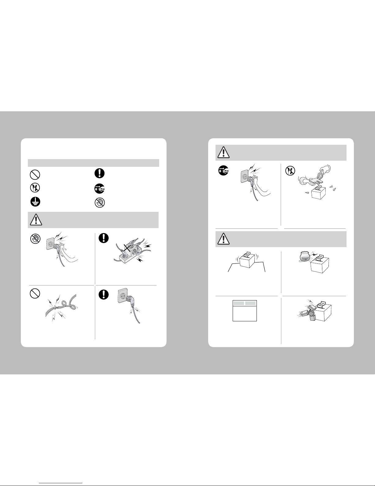
For higher reliability and safety, consider the following precautionary measures.
Read and follow the instructions carefully before running of the product.
1. Safety Caution
Indication
Prohibition
Must follow
Do not disassemble
Unplug the power from
the outlet
Grounding to prevent
electric shock
Do not handle the product
with wet hands
WARNING
WARNING
WARNING
Failure to follow these instructions could result in re, electric shock,
or other injuries, or property damage
Failure to follow these instructions could result in re, electric shock,
or other injuries, or property damage
Failure to follow these instructions could result in re, electric shock,
or other injuries, or property damage
(Potential risk of electric shock or re)
(Potential risk of electric shock or re)
(Potential risk of electric shock or re)(Potential risk of electric shock or re)
Do not pull or touch the power plug with
wet hands.
Do not bend the wire and do not allow the
wire to be pressed by heavy object.
If a power plug is broken or a plug is cut or
worn, do not use it.
Do not overload the power plug into
one outlet.
(Turn o the power at installation,
transportation, wiring and inspection.)
(Potential risk unit malfunction, electric
shock or re. When the product needs
to be repaired, please contact in place
where you ordered.inspection.)
Do not pull out the power plug to turn o
the product.
Do not disassemble, repair or modify the
product.
Dealer
(You may get hurt and it can be broken
when it falls)
(Potential risk of re or unit malfunction)
(Potential risk of re or unit malfunction)
(Potential risk of discoloration or
electric shock)
Do not install the product in uneven or
inclined surface.
If the product that needs to be repaired,
please contact in place where you ordered.
Please do not give excessive shock.
Keep product away from the water and
other material.
5
4
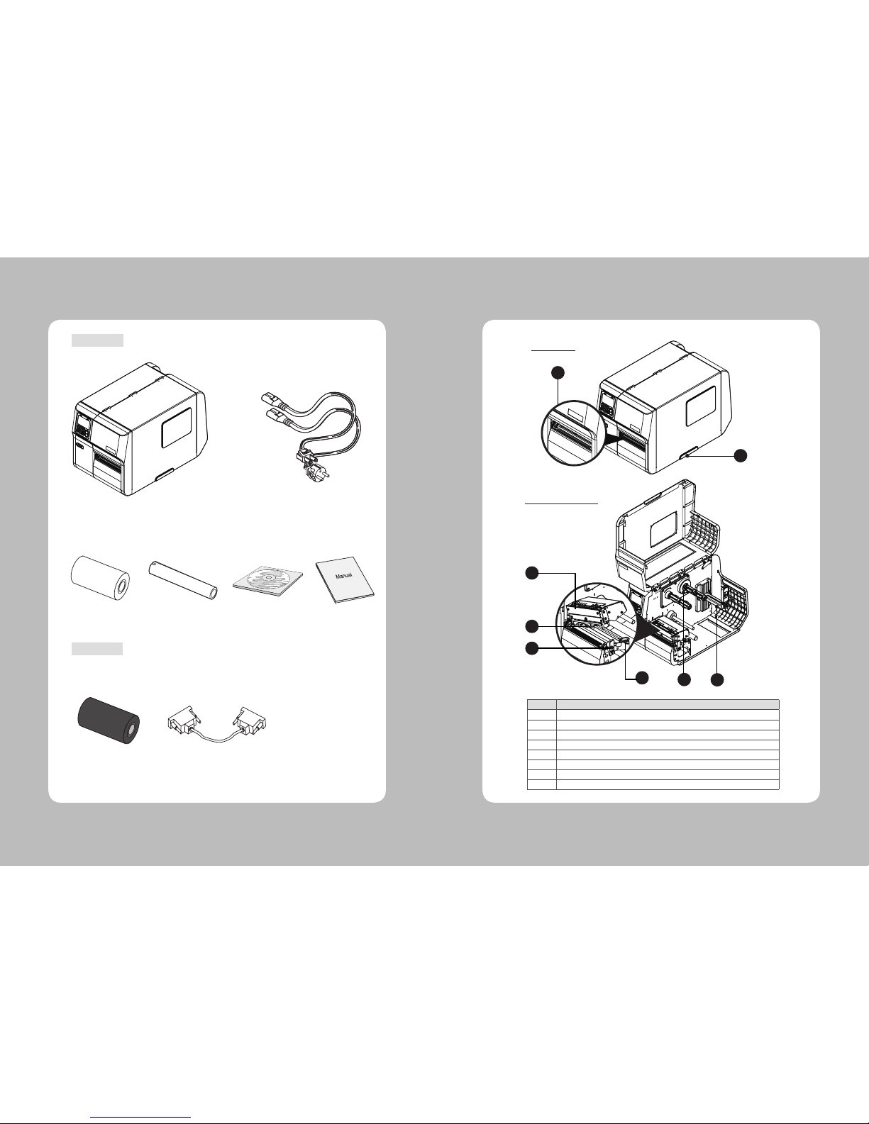
2. Unpacking
Printer
Power Cord(1EA)
Label
Ribbon
Ribbon Core
CD
(User’s Manual)
Quick Manual
3. Inspecting the printer
Interface cable
No.
Designation
1
Paper Exit
2
Door Handle
3
Head ASS’
4
Ribbon Spindle
5
Paper Holder
6
Paper Sensor
7
Print Head Release Lever
8
Paper width Guide
1
2
MAIN VIEW
COVER OPEN VIEW
Optional
Standard
8
7
6
3
4 5
7
6
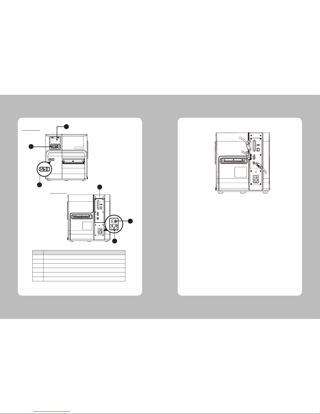
Make sure the printer is turned off then connect the printer to the PC
4. Hooking Up the printer and computer
USB
Serial
Parallel
-PRINTER REAR VIEW-
No.
Designation
9
Control Button
10
Display LCD
11
USB Host
12
Interface Connectors
13
Power Cord Connectors
14
Power Switch
9
10
11
12
FRONT VIEW
REAR VIEW
14
13

9
8
1 2
3
4
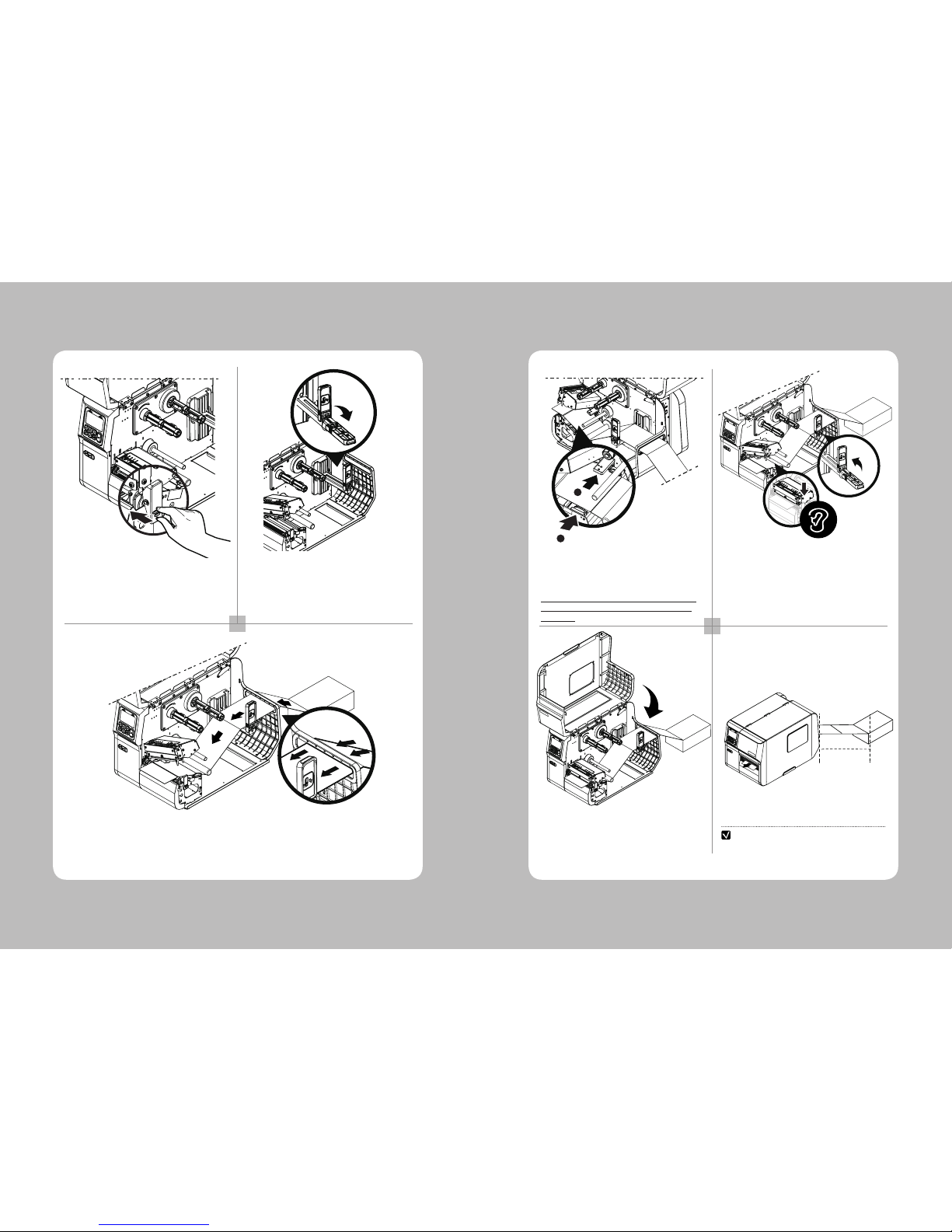
OPEN THE HEAD ASS’Y BY PUSHING THE LEVER.
PLACE THE ROLL OF PAPER ON THE PAPER
HOLDER.
5. Load Label Paper
FLIP DOWN THE PAPER HOLDER GUIDE.
5 6
2
7 8
LOWER THE PRINTER COVER TO THE DIRECTION
OF THE ARROW AS SHOWN IN THE PICTURE.
CLOSE THE PRINTER COVER TO THE END SLOWLY.
1
1. SLIDE THE PAPER UNDER THE PAPER SHAFT.
1. SLIDE THE PAPER INTO THE PAPER SENSOR.
2. ADJUST THE PAPER GUIDE PROPERLY TO FIT
THE PAPER WIDTH.
CAUTION: IF YOU ADJUST PAPER GUIDE NARROWER
THAN THE PAPER WIDTH, IT MAY CAUSE PRINTING
PROBLEMS
AFTER ADJUSTING THE PAPER GUIDE, FLIP UP
PAPER HOLDER GUIDE.
PULL THE PAPER TO THE HEAD ASS’Y AND
CLOSE THE HEAD ASS’Y.
(MAKE SURE TO CHECK THE CLOSING SOUND)
1
2
11
10
1 2
3
OPEN THE HEAD ASS’Y BY PUSHING THE LEVER.
6. Pen folder Paper
FLIP DOWN THE PAPER HOLDER GUIDE.
INSERT THE PAPER INTO THE PAPER ACCESS SLOT AT THE REAR OF THE
PRINTER. SLIDE THE PAPER UNDER THE PAPER SHAFT.
4 5
6 7
1. SLIDE THE PAPER THROUGH THE PAPER
SENSOR.
2. ADJUST THE PAPER GUIDE PROPERLY TO FIT
THE PAPER WIDTH.
CAUTION: IF YOU ADJUST PAPER GUIDE NARROWER
THAN THE PAPER WIDTH, IT MAY CAUSE PRINTING
PROBLEMS.
AFTER ADJUSTING THE PAPER GUIDE, PUT THE
PAPER HOLDER GUIDE UP. PULL THE PAPER TO THE
HEAD ASS’Y AND CLOSE THE HEAD ASS’Y.
(MAKE SURE TO CHECK THE CLOSING SOUND)
2
1
PLACE THE PAPER AT LEAST
THE DOUBLE OF THE PAPER
LENGTH(300MM) DISTANCE AWAY
FROM THE PRINTER.
NOTE
300mm
LOWER THE PRINTER COVER TO THE
DIRECTION OF THE ARROW AS SHOWN IN
THE PICTURE.
CLOSE THE PRINTER COVER TO THE END SLOWLY.
13
12
1 2
3
4
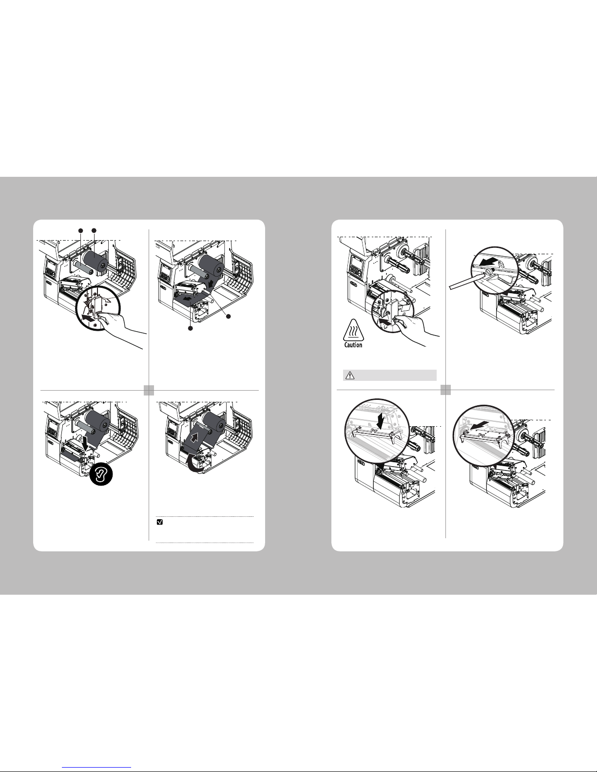
OPEN THE HEAD ASS’Y
BY PUSHING THE LEVER.
1. PLACE RIBBON CORE ON THE HOLDER(1)
2. PLACE THE RIBBON ON THE RIBBON SUPPLY
SPINDLE(2)
Ribbon
Guide Shaft
7. Load Ribbon
1 2
3
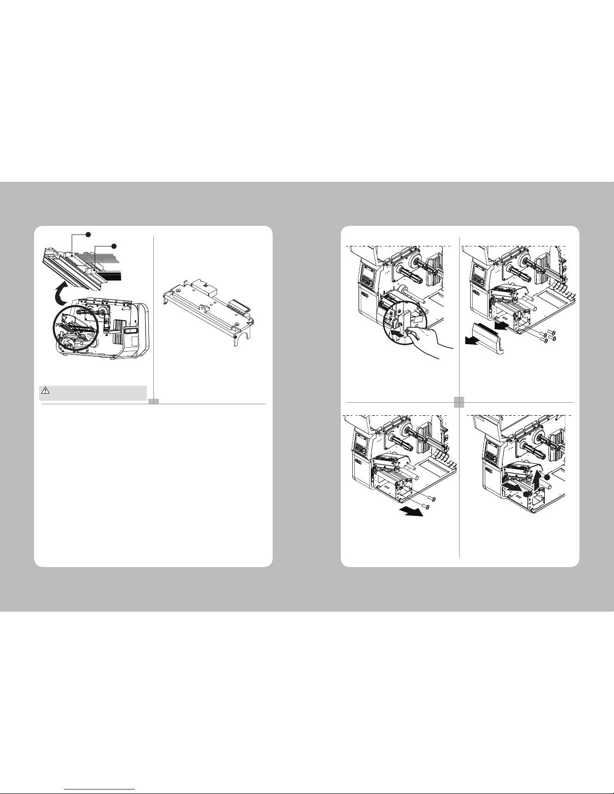
OPEN THE HEAD ASS’Y BY PUSHING THE
BUTTON.
The printhead may be hot
REMOVE HEAD SET SCREW(1) WITH (-) SCREW
DRIVER (YOU MAY USE A COIN).
8. Replace HEAD
PULL THE DETACHED HEAD ASS’Y(1) TO
THE HEAD ASS’Y.
DETACH HEAD ASS’Y TO THE DOWNWARD.
4
1
2
PRESS THE FEED BUTTON TO REMOVE RIBBON
WRINKLE
CHECK
1
2
1. SLIDE THE RIBBON UNDER THE RIBBON
GUIDE SHAFT.
2. PULL THE RIBBON TO THE FRONT OF THE
HEAD ASS’Y.
PRESS THE PUSH BUTTON ON TOP OF THE HEAD
ASS’Y AND LOWER THE HEAD ASS’Y UNTIL IT
LOCKS. MAKE SURE TO CHECK THE CLOSING
SOUND.
PLACE THE RIBBON AS SHOWN IN THE PICTURE
AND FIX ON THE RIBBON CORE BY TAPING.
15
14
5 6
3
REMOVE POWER CABLE AND DATA CABLE.
DETACHED HEAD ASS’Y.
POWER CABLE
DATA CABLE
9. Replace Platen Roller
1 2
3
4
Take care not to allow the print head to become scratched and /or damaged in any way.
1
2
OPEN THE HEAD ASS’Y BY PUSHING THE LEVER. UNSCREW 4 SCREWS(2 INSIDE SCREWS,
2 OUTSIDE SCREWS) AND SEPARATE THE
COVER FRONT OUTPUT TRAY.
1. DETACH THE BEARING AND BUSH.
2. REMOVE THE PLATEN ASS’Y.
1
2
UNSCREW 2 SCREWS TO REMOVE THE HEAD
OPEN LEVER.
17
16
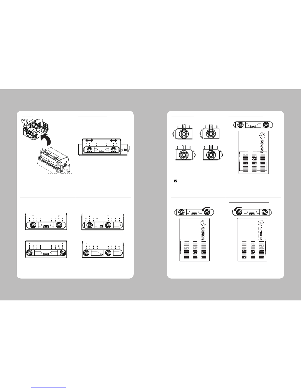
USE THE DIAL TO ADJUST A HEAD PRESSURE
FOR PAPER (0: LOW ~ 3: HIGH)
INCREASE THE RIGHT PRESSURE CONTROL
DIAL TO GET RID OF A DIAGONAL WRINKLE.
INCREASE THE LEFT PRESSURE CONTROL
DIAL TO GET RID OF A DIAGONAL WRINKLE.
LOWER THE PRINTING DENSITY LEVEL TO
GET RID OF A CRESCENT-SHAPED WRINKLE.
THE PRESSURE CONTROL CAN BE MOVED
DEPENDS ON PAPERS AND /OR SIZE.
10. Control HEAD Pressure
LOCATION
MOVE PRESSURE CONTROL
CONTROL PRESSURE CONTROL WRINKLE (CRESCENT)
CONTROL WRINKLE (DIAGONAL LINE)
CONTROL WRINKLE (DIAGONAL LINE)
THE PRESSURE CONTROL CAN BE POSITIONED
TO ACHIEVE THE BEST PRINT QUALITY.
(2-2, 3-3)
THE PRESSURE CONTROL CAN BE POSITIONED
TO ACHIEVE THE BEST PRINT QUALITY.
(2-0, 3-0)
FOR THE 4 INCH PAPER FOR LESS THAN 3 INCH PAPER
- THE LEVER IN CIRCLE IS THE HEAD PRESSURE
ADJUSTER.
- YOU CAN ADJUST THE PRINTING BALANCE BY
CONTROLLING THE HEAD PRESSURE AND
CHANGING THE POSITION OF THE HEAD
PRESSURE CONTROLLER.
NOTE
ROTATE THE DIAL CONTINUOUSLY TO GO
BACK TO ‘0’
(2-0)
(3-3)
(2-2)
(3-0)
MODEL: B40
LABEL PRINTER TEST
BARCODE : CODE39
Q’TY: 3PCS
SD820462
SD820462
SD820462
MODEL: B40
LABEL PRINTER TEST
BARCODE : CODE39
Q’TY: 3PCS
SD820462
SD820462
SD820462
MODEL: B40
LABEL PRINTER TEST
BARCODE : CODE39
Q’TY: 3PCS
SD820462
SD820462
SD820462
(0)
(2)
(1)
(3)
 Loading...