

All specifications are subject to change without notice
4” DESKTOP LABEL PRINTER
MODEL : LK-B10

RISK OF EXPLOSION IF BATTERY IS REPLACED BY AN INCORRECT TYPE.
DISPOSE OF USED BATTERIES ACCORDING TO THE INSTURECITONS

2
3
Table of Contents
1. Unpacking 3
2. Inspecting the printer 4
3. Attaching Power Supply 6
4. Hooking Up the printer and Computer 7
5. Loading the Paper 8
6. Loading Ribbon 10
7. Self Test 12
8. Interface 13
9. Media Roll Size 15
10. Labels 16
11. Tags and Strip with Slots 17
12. Tags and Strip with Black Marks 18
13. Plain Continuous Stock 19
6SHFL¿FDWLRQV 20
15. Command List 22
1. Unpacking
Printer Power Cord(1EA)
Power Supply
Sample LabelsSample Ribbon
Ribbon Spindle (2EA) Paper Spindle
Core
Manual
4
5
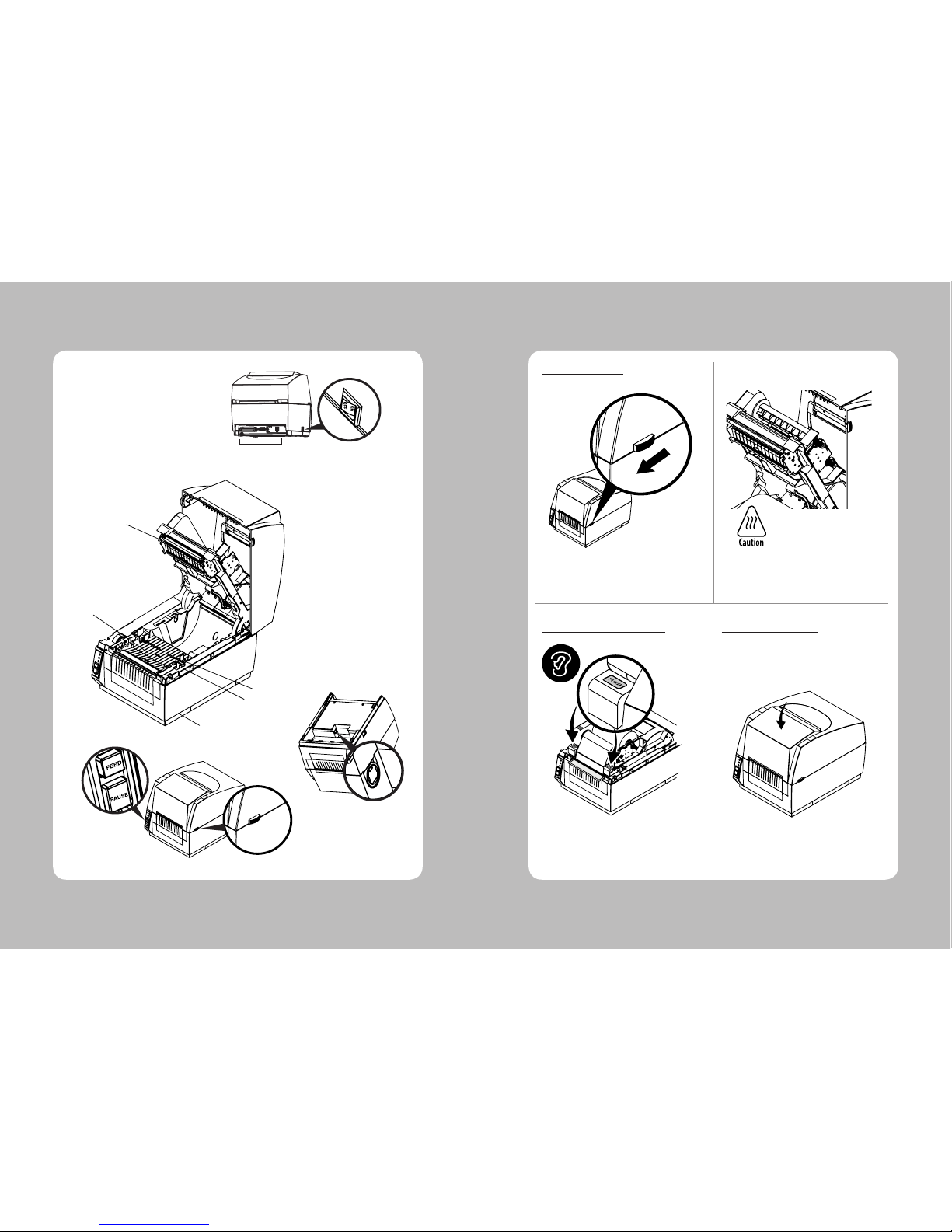
2. Inspecting the printer
Open the upper cover by pushing the knob in
the direction of the arrow
Make sure to be careful of the HOT head
Make sure you hear the closing sound of the
paper upper guide.
Close the upper cover and make sure you hear
the closing sound of the upper cover.
2SHQLQJWKHSULQWHU
&ORVLQJWKHSDSHUXSSHUJXLGH &ORVLQJWKHXSSHUFRYHU
Power Supply
Printer Head
Head Release Lever
Paper Sensor
Bottom Cover
Button
Interface Connectors
Power Switch
Paper width Guide
Upper Cover Knob
6
7
1 2
3
4
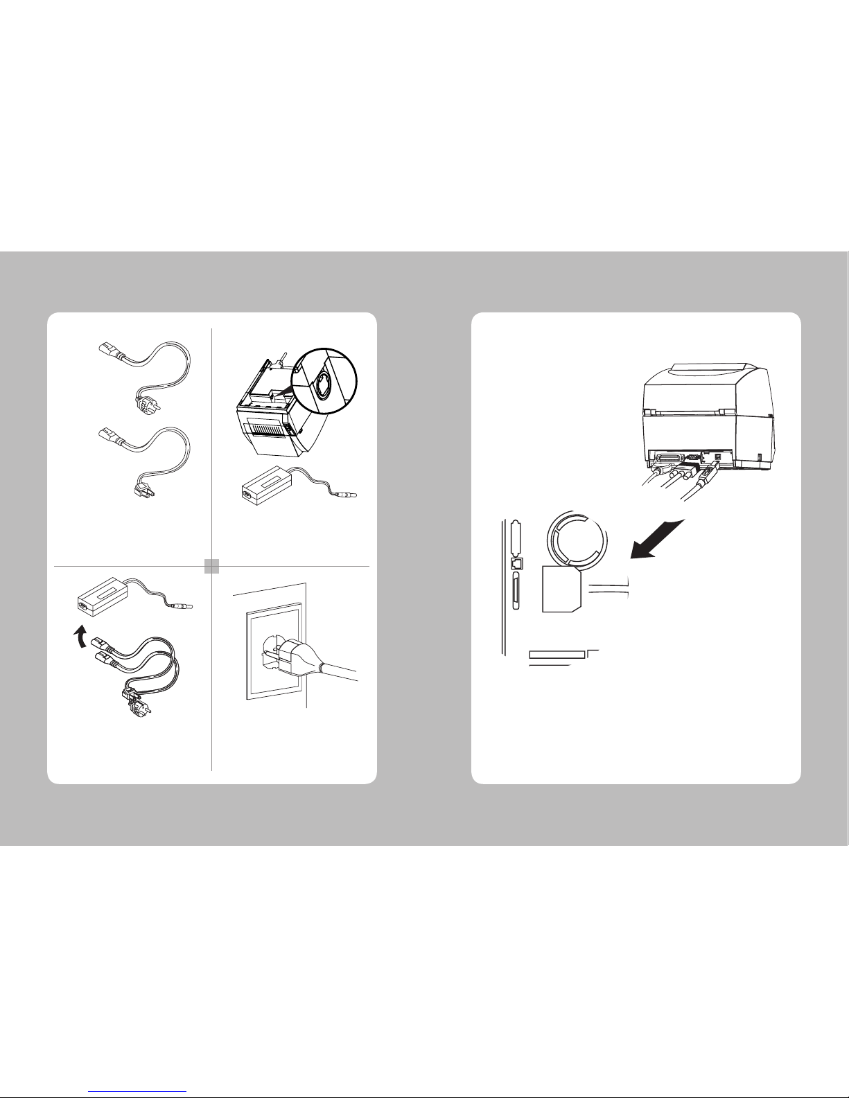
Check the specification of the AC power cord
if it is correct with your power system
Turn off the power of the printer and connect
the power supply to the printer
Connect the AC power cord to the power supply
Insert a plug into the outlet
3. Attaching Power Supply
220VAC
115VAC
Make sure the printer is turned off then connect the printer to the PC
4. Hooking Up the printer and computer
USB(Option)
Serial
Parallel
-Computer-
-Printer-

8
9
5 6
7
8
1 2
3
4
Turn off the printer and open the upper cover by
pushing the in the direction of the arrow.
Open the paper width guide by pushing it to the
right & left sides.
5. Loading the Paper
Rise up the paper upper guide by pulling the
head release lever
Pull out one of the adjustable width tabs.
Insert a paper roll replace the tab and center.
Paper Fixing Tap
Adjust the paper width guide to meet the paper
width
Close the upper cover and make sure you hear
the closing sound of the upper cover.
Insert paper roll into the printer
Make sure you hear the closing sound of the
paper upper guide.

10
11
4 5
6
7
1 2
3
Remove the vinyl covering on the ribbon.
Depress the indicated button on the ribbon
spindle while inserting the ribbon roll.
Insert one side of the ribbon spindle
6. Loading Ribbon
Pull out the ribbon edge through
ribbon mechanism as shown in the
picture
Ribbon
Spindle
Ribbon
Insert one side of the ribbon spindle Push the other side of the ribbon spindle down
to secure it.
Turn the adjustment knob in the arrow direction
to tighten the ribbon.
Attach the ribbon to the core with tape as shown.
detail A
Push the other side of the ribbon spindle down to
secure it.
(b)
(c)
(a)

12
13
1 2
3
4
7. Self Test
Turn off the printer While holding down the feed button,
turn on the printer
Set free the feed button The printer starts printing some basic information
8. Interface
,QWHUIDFH&RQQHFWRUV
<9 Pin Serial> <Centronics Parallel>
<Wi-fi>
Option
Standard
<USB “B” Type> <Ethernet>

14
15
9Pin Serial Interface
Pin Signal I/O Description
2 RXD Input Printer receive data line RS-232C level
3 TXD Output Printer transmit data line RS-232C level
4, 7 DTR Output Printer handshake to host line RS-232C level
5 GND - System Ground
6 DSR Input Data Send Ready
1,8,9 NC -
Centronics Parallel Interface
Pin Signal I/O Description
1 STROBE- Input Synchronize signal Data received
2~9 DATA0~7 Input/Output Data bit Transmitted 0~7
10 ACK- Output Data receiving completed.
11 BUSY Output Impossible to print of data receiving.
12 PE Output Paper empty
13 SELECT Output Printer status for ON/OFF line
14 AUTO FEED- Input Paper auto feed signal
15 GROUND - System ground
16 GROUND - System ground
17 NC 18 LOGIC-H - +5V
19~30 GROUND - System ground
31 INIT- Input Initialize
32 ERROR- Output Printer error
33 GROUND - System ground
34 NC 35 +5V - +5V
36 SELLECT IN- Input Printer select signal
USB Interface
Pin Signal I/O Description
1 +5V - +5V
2 DATA- - Printer transmit data line
3 DATA+ - Printer transmit data line
4 GND - System Ground
Ethernet Interface
Pin Signal I/O
1 Data Out + Output Data +
2 Data Out - Output Data 3 GND Ground
4 Data IN + Input Data +
5 Data IN - Input Data 6 N.C
7 N.C
8 N.C
9. Media Roll Size
Core
Diameter(A) 25.4 or 38.1 mm (1.0 or 1.5 inches)
Max. width 118 mm (4.65inches)
Roll
Max.diameter(B) 125 mm (5 inches)
Max.media width(C) 118 mm (4.65 inches)
Min.media width(C) 18 mm (0.7 inches)
Max.media thickness 0.15 mm (0.006 inches)
Min.mdeia thickness 0.06 mm (0.003 inches)
All types of media should normally be wound with the printable side facing outwards and unroll from
the top of the roll.
However tags and continuous strip can optionally be wound with the printable sidefacing inwards and
unroll from the bottom of the roll as long as they are not used for cut-off operation.
Protect the media against sand, grit, and other hard particles during printing and storage.
Keep the cover closed. Even very small foreign particles may cause severe harm to the
delicate printhead.

16
17
10. Labels
<-- a --> Media width (inch, liner)
Maximum 118.0 mm (4.65 inches)
Minimum 18 mm (0.7 inches)
<-- b --> Label length
Minimum 10 mm (0.39 inches)
<-- c --> Label gap height
Maximum 10 mm (0.39 inches)
Minimum 2 mm (0.08 inches)
Liner
Opacity 75%
11. Tags and Strip with Slots
<-- a --> Tag or strip width
Maximum 118.0 mm (4.65 inches)
Minimum 18 mm (0.7 inches)
<-- b --> Tag length
Minimum 10 mm (0.39 inches)
<-- c --> Detection slot width
Minimum 14 mm (0.55 inches)
<-- d --> Detection slot height
Maximum 10 mm (0.39 inches)
Minimum 2 mm (0.08 inches)
The label gap sensor is offset 4.5 mm(0.177 inches) to the right of the center fo the media path.

18
19
a
c
TICKETS,TAGS, &
CONTINUOUS STRIP
d
b
12. Tags and Strip with Black Marks
<-- a --> Tag or strip width
Maximum 118.0 mm (4.65 inches)
Minimum 18 mm (0.7 inches)
<-- b --> Tag length
Minimum 10 mm (0.39 inches)
<-- c --> Black mark width
Minimum 14 mm (0.55 inches)
<-- d --> Black mark height
Maximum 10 mm (0.39 inches)
Minimum 3 mm (0.12 inches)
The black mark sensor is offset 10 mm (0.394 inches) to the right of the center of the media path.
Max. reflectance 5% at 940 nanometer. Carbon black.
13. Plain Continuous Stock
The printer can use continuous stock without any detection slots or black marks.
The printer must be set for continuous stock by the Q command.
The length of each copy is decided by the size of the print image and any additional media feed is
decided by the Q command.
Continuous stock cannot be used in the Test (Dump) Mode.
<-- a --> Tag or strip width
Maximum 118.0 mm (4.65 inches)
Minimum 18 mm (0.7 inches)

20
21
Print method Thermal Transfer and Direct Thermal
Print speed(max) 102mm/sec
Print width(max) 104mm (4.1”)
Print length(max) 630mm (24.8”)
Resolution 203dpi, 8 dots/mm
Paper Width(min~max) 18mm ~118 mm (0.7” ~ 4.64”)
Paper roll size(max) 127mm (5.0”)
Paper thickness 0.06~0.18mm
Paper Type Label , Tag, Continuous, Fanfold
Paper sensor Label gap, Notch, Black Mark
Ribbon width(outside diameter) 18mm to 110mm (1.3~4.3”)
Ribbon length 300M, Ø 64 mm (2.5”)
Interface Standard Serial(RS-232C), Parallel(IEEE-1284)
Option USB, Ethernet, Wireless Lan 802.11b
Memory Standard 8MB SDRAM, 3.5MB Flash
Option 8MB Flash
Serial baud rate 115200bps
Auto Cutter (Option) Life 0.06~0.15mm: 500,000 cuts / 0.15~0.18:300,000 cuts
Type Guillotine
Peeler Option
Programming Language EPLዝ (Eltron Programming language)
Barcode 1D Code39, Code128 with subsets A/B/C, Code
Interleaved 2 of 5, UPC-A and UPC-E with 2
EAN-8 and EAN-13 with 2 or 5 Digit Extens
Postnet, Plessey, German Post Code, MS
2D MaxiCode, PDF417, DATAMATRIX, QR CO
Font Specification 6bitmapped 8x12, 10x16, 12x20, 14x24,32x48,
24x24(KSC5601)
Weight 7.9lbs (3.6kg)
Size (W x D x H) 215x287x231
14. Specifications
(1) FCC PART15 CLASS A
(2) CE EMCD (CE-EMCD Class B should use Parallel shield Cable complied with IEEE-1284 standards)
(3) UL/cUL (UL 60950-1)
(4) MIC CLASS A
(5) RoHS (TUV)
(6) CCC
(1) Input Voltage DC 24V ± 10%
(2) Current Consumption
Operating: Approx. 1.5 A (at ASCଧGprinting)
Peak : Approx. 10 A
(at print duty 100%, For 10 seconds or less)
Stand-by : Approx. 0.15 A
(3) Power Connector
3URGXFW6SHFLILFDWLRQV &HUWLILFDWLRQ
(OHFWULFDO&KDUDFWHULVWLFV

22
23
15. Command List
No. Command Description
1 A ASCዝText
2 AUTOFR Automatic Form Printing
3 B Bar Code
4 B RSS-14 Bar Code
5 b Data Matrix
MaxiCode
PDF417
6 C Counter
7 C Cut Immediate
8 D Density
9 EI Print Soft Font Info.
10 EK Delete Soft Font
11 eR User Definable Error Response
12 ES Store Soft Font
13 f Cut/Peel Position
14 FE End Form Store
15 FI Print Form Info.
16 FK Delete Form
17 FR Retrieve Form
18 FS Store Form
19 GG Retrieve Graphics
20 GI Print Graphics Info.
21 GK Delete Graphic
22 GM Store Graphic
23 GW Direct Graphic Write
24 I Character Set Selection
25 JB Disable Top Of Form Backup
26 JC Disable Top Of Form Backup –All Cases
27 JF Enable Top Of Form Backup
28 LE Line Draw Exclusive OR
29 LO Line Draw Black
30 LS Line Draw Diagonal
31 LW Line Draw White
32 M Memory Allocation
33 N Clear Image Buffer
34 o Cancel Customized Settings
35 oB Cancel Customize Bar Code
36 oE Line Mode Font Substitution
37 oH Macro PDF Offset
38 oM Disable Initial Esc Sequence Feed
39 oR Character Substitution(Euro)
40 oW Customize Bar Code Parameters
No. Command Description
41 O Options Select
42 OEPL1 Set Line Mode
43 P Print
44 PA Print Automatic
45 Q Set Form Length
Transmissive(Gap)Sensor
Black Line Sensor
Continuous Stock
46 q Set Form Width
47 r Set Double Buffer Mode
48 R Set Reference Point
49 S Speed Select
50 TD Define Date Layout(& Print Date)
51 TS Set Real Time Clock
52 TT Define Time Layout(& Print Time)
53 U Print Configuration
54 UA Enable Clear Label Counter Mode
55 UB Reset Label Counter Mode
56 UE External Font Information Inquiry
57 UF Form Information Inquiry
58 UG Graphic Information Inquiry
59 UI Host Prompts/Codepage Inquiry
60 UM Codepage& Memory Inquiry
61 UN Disable Error Reporting
62 UP Codepage& Memory Inquiry/Print
63 UQ Configuration Inquiry
64 US Enable Error Reporting
65 V Define Variable
66 W Windows Mode
67 xa Sense Media
68 X Box Draw
69 Y Serial Port Setup
70 Z Print Direction
71 ? Download Variables
72 ^ @ Reset Printer
73 ^ default Set Printer to Factory Defaults
74 ^ ee Status Report – Immediate

Rev. 1.0
SEWOO TECH CO.,LTD.
Doosung BD, 689-20, Geumjeong-dong, Gunpo-si, Gyeonggi-do, 435-862, Korea
TEL : +82-31-459-8200 FAX : +82-31-459-8880
www.miniprinter.com
 Loading...