


To: AirWalk communications, Co., Ltd.
User’s Manual
Model no. STS800-48HM-D-AO SYSTEM
881, Gwanyang-2dong, Dongan-gu, Anyang-si,
Gyeonggi 431-804, Republic of Korea
Phone: 031-422-0031 Fax: 031-425-9931
Reference
User Manual
Revision IR Page 1 / 24
Design Document for
Slim RU Version 1.2
Revision history
Rev. Date Chap. Changes Note
1.0 JUL.31, 2009 First draft
Design Document for
Slim RU Version 1.2

Reference
User Manual
Revision IR Page 2 / 24
Design Document for
Slim RU Version 1.2
Table of Contents
1. Introduction............................................................................................................ 3
2. Installation.............................................................................................................. 4
3. Program configuration............................................................................................ 5
3.1. GUI.................................................................................................................. 5
3.1.1. Main window.......................................................................................................5
3.1.2. System window...................................................................................................5
3.1.2.1. System info...............................................................................................6
3.1.2.2. Alarm info..................................................................................................7
3.1.2.3. History info................................................................................................7
3.1.2.4. Control info................................................................................................8
3.1.2.5. DIP switch status.......................................................................................8
3.1.2.6. Down load.................................................................................................8
3.2. MMI................................................................................................................. 9
3.2.1. MMI connection..................................................................................................9
3.2.2. General commands..........................................................................................10
3.2.3. Test commands ................................................................................................13
3.2.4. Emergency recovery mode...............................................................................22
3.2.4.1. Entering...................................................................................................22
3.2.4.2. GUI connection.......................................................................................22
3.2.4.3. Download................................................................................................23
Reference
User Manual
Revision IR Page 3 / 24
Design Document for
Slim RU Version 1.2
1. Introduction
It is monitor and controls all the functions of Slim-RU series based on graphic user interface
(GUI) or Man Machine Interface (MMI).
Slim-RU GUI program offers straight forward user interface under Windows 2000 or Windows
XP operating system. Therefore it needs only short training course for maintenance
technicians.
Also MMI program performs all functions of GUI. But it has extra commands for detail such as
test purpose command set.
Models Tx Frequency
STS800-48HM-D-AO SYSTEM 384CH/425CH/630CH
※ Fc = (0.03 X CH Number) + 870MHz
* NOTE 1: Before run GUI or MMI program, PC or laptop computer should connect to Slim-RU
with RJ-45 cable.
* NOTE 2: When the cable connects Master Slim-RU, you can handle all Slim-RUs such as
master, slave1, and slave2. But if you connect it to slave 1 or slave 2, you can handle
only it.
Reference
User Manual
Revision IR Page 4 / 24
Design Document for
Slim RU Version 1.2
2. Installation
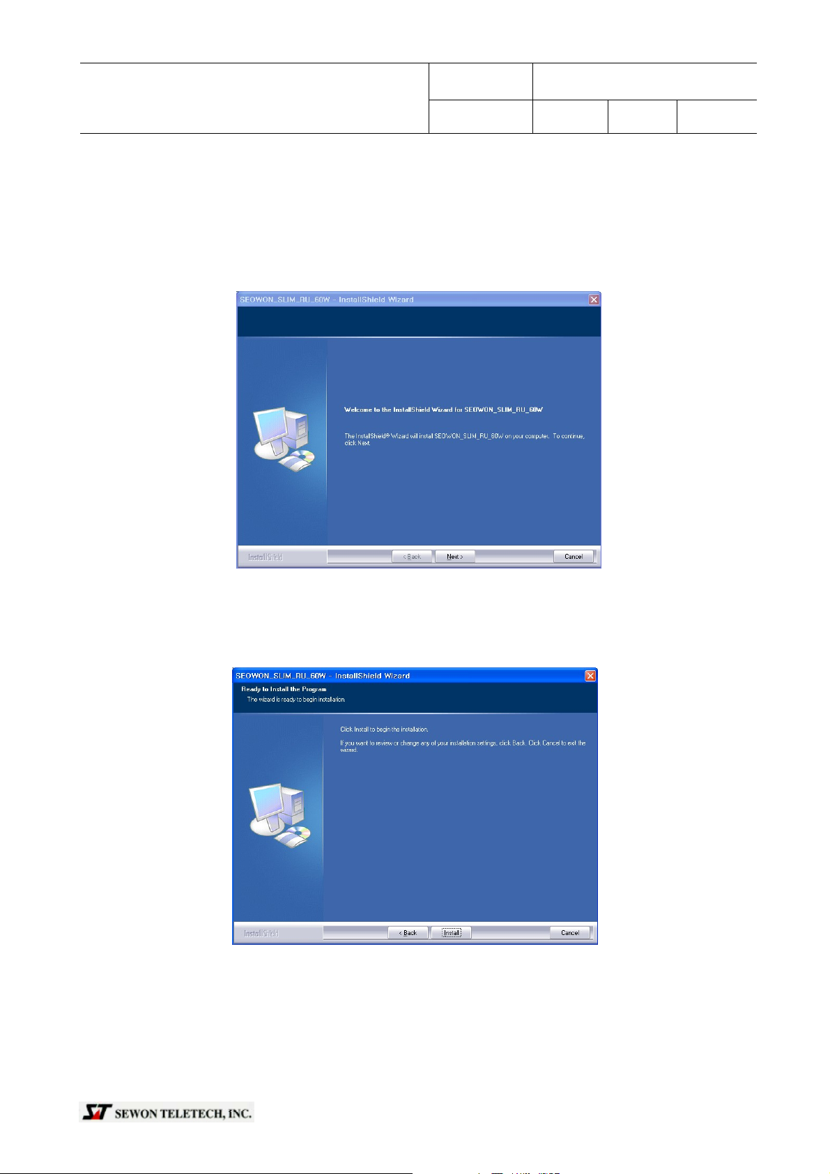
To install Slim-RU GUI program, double click “Setup_SLIM_RU_60W_2009.07.01.V1.0.exe”. Then
InstallSheild Wizard shows like figure 1. Click “Next” button.
Click “Install” button like figure 2.
Figure1. Initial page
Figure2. Installation
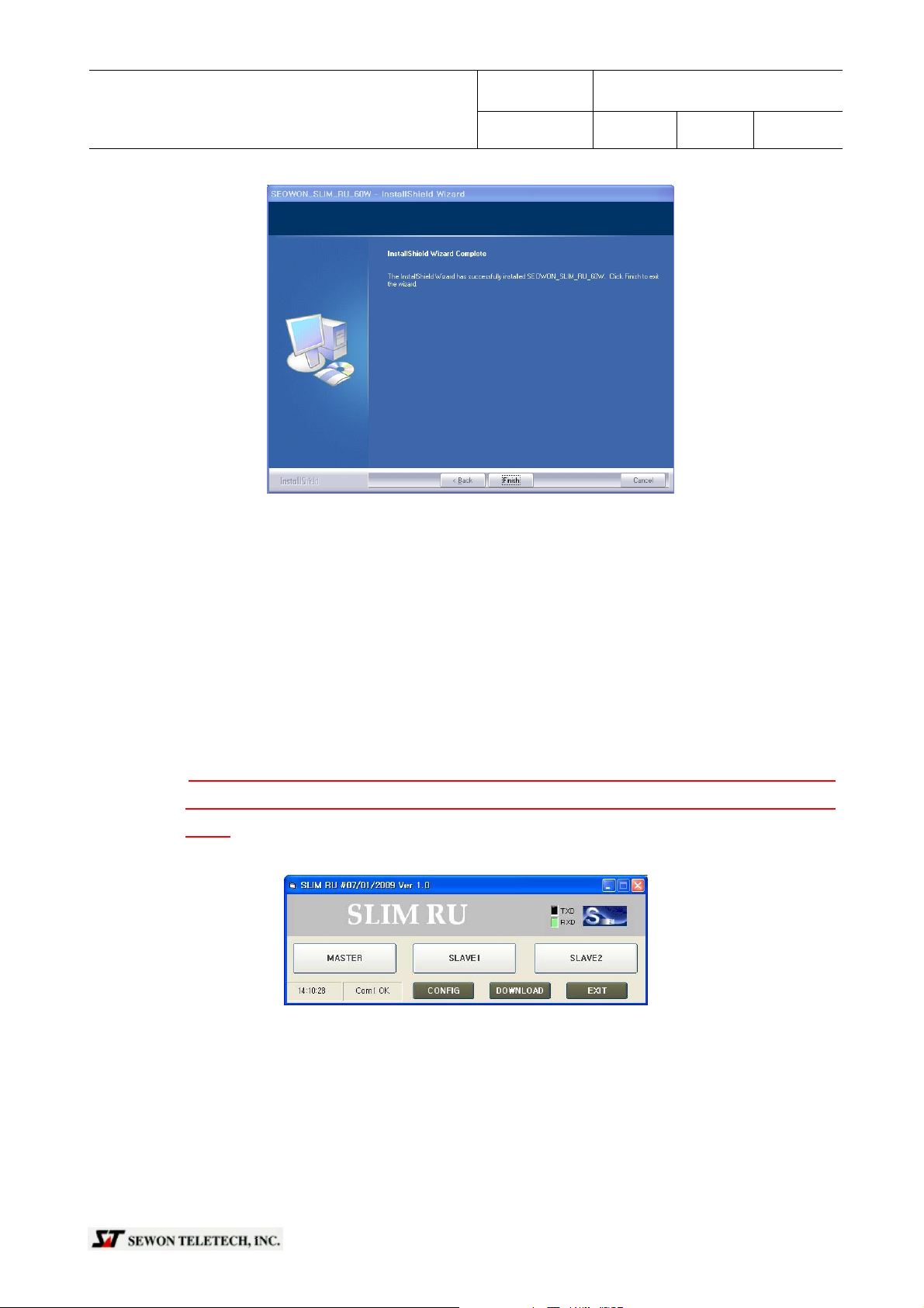
InstallShield Wizard shows the last page when it is done like figure 3. Click “finish” button. Finally,
installation is done. Please confirm file on “start-program-AirWalk-SLIM_RU_60W”
Reference
User Manual
Revision IR Page 5 / 24
Figure3. Finish
Design Document for
Slim RU Version 1.2
3. Program configuration
3.1. GUI
3.1.1. Main window
It offers monitoring, setting, and downloading firmware to Slim-RU. You can select whatever yo u
want to handle.
* NOTE : When the cable connects Master Slim-RU, you can handle all Slim-RUs such as
master, slave1, and slave2. But if you connect it to slave 1 or slave 2, you can handle
only it
Figure4. Main window
* Configuration for serial port
Click “CONFIG” button and set proper communication port and 57600-8-N-1 in the dialog box
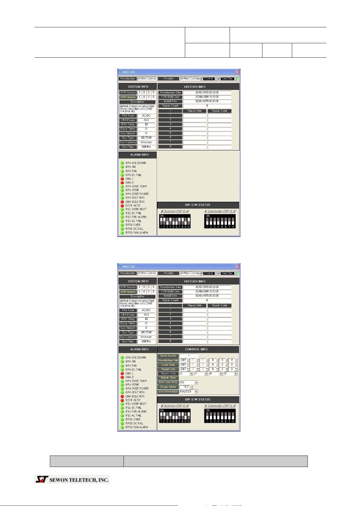
3.1.2. System window
It offers monitoring and setting in details
Reference
User Manual
Revision IR Page 6 / 24
Design Document for
Slim RU Version 1.2
Figure5. System window
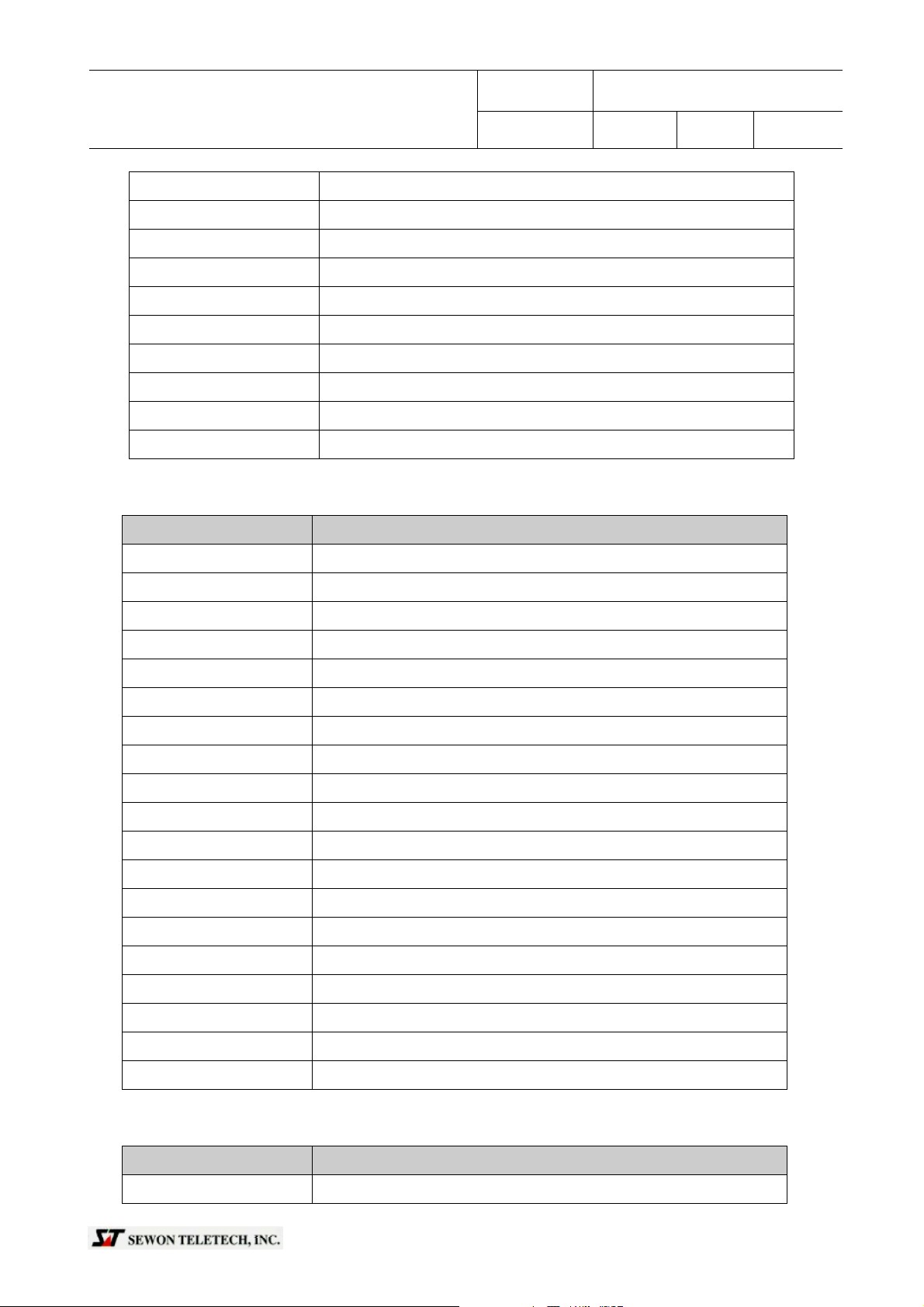
For details, it offers “hidden window” with pressing “ctrl + p”
3.1.2.1. System info
Items Descriptions
Figure6. Hidden window
User Manual
F/W Version Shows Frimware Version
H/W Version Shows H/W Version
Description Shows brief system information
PSU TYPE Shows PSU type and information
HPA Power Shows HPA power in dBm
HPA Temp Shows HP A temperature
Equip Temp Shows Slim-RU temperature
Sys Version Shows system version
Sys Capacity Shows Slim-RU capacity
Sys Freq. Shows sys Frequency
3.1.2.2. Alarm info
Items Descriptions
Reference
Revision IR Page 7 / 24
Design Document for
Slim RU Version 1.2
HPA SHUTDOWN Shows HPA shutdown status
HPA ON Shows HPA enable or disable status
HPA FAN Shows fan operation is normal or not
HPA DC FAIL Shows the status of DC power to HPA
LNA_1. Shows LNA_1 status is normal or not
LNA_2 Shows LNA_2 status is normal or not
HPA OVER TEMP Shows HPA over temperature is normal or not
HPA VSWR Shows HPA VSWR is normal or not
HPA OVER POWER Shows HPA output power is over or not
HPA DELETION. Shows HPA deletion or not
LNA DELETION Shows LNA deletion or not
KEEP ALIVE Shows Slim-RU communicates to AW96 normally or not
PSU OVER HEAT Shows power supply is over heat or not
PSU DC FAIL Shows power supply’s DC is normal or not
PSU FAN FAIL Shows power supply’s fan is normal or not
PSU AC FAIL Shows power supply’s AC is normal or not
RPSU OVER HEAT Shows RPSU is over heat or not
RPSU DC FAIL. Shows RPSU DC is normal or not
RPSU FAN FAIL Shows RPSU’s fan is normal or not
3.1.2.3. History info
Items Descriptions
Manufacture Date Shows the date of RRCU manufacturing

Reference
User Manual
Revision IR Page 8 / 24
F/W Build Date Shows the date of firmware building
Install Date Shows the date of Slim-RU installation
Repair Count Shows the number of Slim-RU repair
Repair Date Shows the date of repair date
Repair Code Shows the date of repair history
3.1.2.4. Control info
Items Descriptions
Serial Number Sets RRCU serial number
Manufacture Date Sets RRCU manufacturing date
Install Date Sets Slim-RU installation date
Repair Date Sets repair date
Repair Code Sets repair history
Design Document for
Slim RU Version 1.2
Repair Clear Clears repair all data
HPA CONTROL Turns on or off HPA
Power Offset Adjusts HPA power offset
SYSTEM MODE Set system mode such as master, slave1, or slave2
3.1.2.5. DIP switch status
* System DIP switch
It sets each type and details for Slim-RU. Each bit explains the status like follows
Figure7. Dip switch status
3.1.2.6. Down load
File open: To select file to be downloaded click it.
Download: It starts download to Slim-RU. The figure shows in the pro cessing with file progress bar

User Manual
Cancel: It cancel download
3.2. MMI
Reference
Revision IR Page 9 / 24
Figure8. Download proceding
Design Document for
Slim RU Version 1.2
3.2.1. MMI connection
In order to connect to MMI on Slim-RU, Hiper terminal on Windows or any types of serial
communication program like Tera Term. (Hereafter Tera Term)
Set proper communication port and 57600-8-N-1 like figure XX on “Serial port setup” dialog box.
Figure9. Main screen of Tera Term
Then you can see below terminal screen with prompt “SLIM_RU:MST:> like figure 10 (b) when you
hit “Enter” key several times.
If prompt is “SLIM_RU:###” like figure XXX (a), it means no communication with upper system, e.g.
AW96 if you connect master of Slim-RU or master if you connect slave 1 or 2 of Slim-RU. Please
confirm it.

User Manual
(a) No connections with upper system (b) Connected properly
Figure10. Connecting status
3.2.2. General commands
* ver: shows firmware version like below figure
Reference
Revision IR Page 10 / 24
Design Document for
Slim RU Version 1.2
Figure11. command example “ver”

Reference
User Manual
Revision IR Page 11 / 24
Design Document for
Slim RU Version 1.2
* reset: reboots Slim-RU without manual cycling. Reboot process is shown below
Figure12. command example “reset”
* status [master/slave1/slave2] : shows the status that you connected briefly without any option
like figure 13 (a) or with options [master/slave1/slave2] like (b) to (d). But you cannot see your
upper system.
(a) status without option (b) status with option “master”

Reference
User Manual
Revision IR Page 12 / 24
Design Document for
Slim RU Version 1.2
(c) Status with option “slave1” (d) Status with option “slave2”
Figure13. command example “status”
Commands Descriptions
system shows Slim-RU system ID
hpa enable shows status of HPA enable or disable
hpa fwd power shows HPA power in dBm
hpa temp shows HPA temperature
equip temp shows Slim-RU temperature
hpa shutdown shows HPA shutdown status as an “ON or OFF”
hpa fan shows fan operation is normal or not as an “ON or OFF”
hpa dc fail shows the status of DC power to HPA as an “ON or OFF”
lna_1 shows LNA_1 status is normal or not as an “ON or OFF”
lna_2 shows LNA_2 status is normal or not as an “ON or OFF”
hpa over_temp shows HPA over temperature is normal or not as an “ON or OFF”
hpa vswr shows HPA VSWR is normal or not as an “ON or OFF”
hpa over_power shows HPA output power is over or not as an “ON or OFF”
hpa_deletion shows HPA deletion or not as an “ON or OFF”
lna_deletion shows LNA deletion or not
master keep alive shows master communicates to AW96 normally or not as an “ON or
OFF”
slave1 keep alive shows master communicates to slave1 normally or not as an “ON or
OFF”
slave2 keep alive shows master communicates to slave2 normally or not as an “ON or
OFF”

Reference
User Manual
Revision IR Page 13 / 24
Design Document for
Slim RU Version 1.2
psu over heat shows power supply is over heat or not as an “ON or OFF”
psu dc fail shows power supply’s DC is normal or not as an “ON or OFF”
psu fan fail shows power supply’s fan is normal or not as an “ON or OFF”
psu ac fail shows power supply’s AC is normal or not as an “ON or OFF”
rpsu over heat shows RPSU is over heat or not as an “ON or OFF”
rpsu dc fail shows RPSU DC is normal or not as an “ON or OFF”
psu fan fail shows RPSU’s fan is normal or not as an “ON or OFF”
3.2.3. Test commands
It offers several fake alarms command for test purpose
Commands Descriptions
testcmd vtralm
[on/off]
Report fake alarm to upper system with ignoring present status
ex.) compare “HPA shutdown” after “testcmd vtralm on”

User Manual
testcmd allalm Report all fake alarm to upper system
(ex.) compare all alarm items on the screen after “testcmd allalm”
Reference
Revision IR Page 14 / 24
Design Document for
Slim RU Version 1.2

testcmd hfa
Reference
User Manual
Revision IR Page 15 / 24
Report fake HPA fan alarm to upper system
Design Document for
Slim RU Version 1.2
[on/off]
(ex.) confirm “HPA FAN” after “testcmd hfa on”
testcmd hdcf Report HPA DC fail alarm to upper system
(ex.) confirm “DC FAIL” after “testcmd hdcf on”

testcmd HL2F
Reference
User Manual
Report fake LNA_2 alarm to upper system
Design Document for
Slim RU Version 1.2
Revision IR Page 16 / 24
[on/off]
(ex.) confirm “LNA_2” after “HL2F
testcmd HL1F
[on/off]
Report fake LNA_1 alarm to upper system
(ex.) confirm “LNA_1” after “testcmd HL1F on”
”

testcmd HOVT
Reference
User Manual
Revision IR Page 17 / 24
Report fake over temperature alarm to upper system
Design Document for
Slim RU Version 1.2
[on/off]
(ex.) confirm “Over temp” after “testcmd hovt on”
testcmd HVSWR
[on/off]
Report fake HPA VSWR alarm to upper system
(ex.) confirm “VSWR” after “testcmd hvswr on”

Testcmd HOVP
Reference
User Manual
Revision IR Page 18 / 24
Report fake HPA over power alarm to upper system
Design Document for
Slim RU Version 1.2
[on/off]
(ex.) confirm “Over power” after “testcmd hovp on”
testcmd poh
[on/off]
Report fake over heat alarm to upper system
(ex.) confirm “PSU over heat” after “testcmd poh on”

testcmd PDCF
Reference
User Manual
Revision IR Page 19 / 24
Report fake PSU DC fail alarm to upper system
Design Document for
Slim RU Version 1.2
[on/off]
(ex.) confirm “PSU DC Fail” after “testcmd pdcf on”
testcmd PFF
[on/off]
Report fake PSU fan fail alarm to upper system
(ex.) confirm “PSU fan” after “testcmd pff on”

Reference
User Manual
Revision IR Page 20 / 24
Design Document for
Slim RU Version 1.2
testcmd PACF
[on/off]
Report fake HPA fan alarm to upper system
(ex.) confirm “PSU AC failAN” after “testcmd pacf on”
testcmd RPOH
[on/off]
Report fake RPSU over heat alarm to upper system
(ex.) confirm “RPSU over heat” after “testcmd RPOH on”

testcmd RPDCF
Reference
User Manual
Revision IR Page 21 / 24
Report fake RPSU DC fail alarm to upper system
Design Document for
Slim RU Version 1.2
[on/off]
testcmd RPFF
(ex.) confirm “RPSU DC fail” after “testcmd rpdcf on”
Report fake RPSU fan alarm to upper system
[on/off]
(ex.) confirm “RPSU fan fail” after “testcmd rpff on”

Reference
User Manual
Revision IR Page 22 / 24
Design Document for
Slim RU Version 1.2
3.2.4. Emergency recovery mode
3.2.4.1. Entering
You can download firmware when Slim-RU does not operate properly.
Press “enter” within 7 sec. when it boots up. Fig.14 shows the screen when it enters on
emergency recovery mode
Figure14. Entering emergency recovery mode
* You can close window or disconnect com port when you want finish. Please confirm emergency
recovery mode prompt”@[OPR]System ready for download” before that.
3.2.4.2. GUI connection
Run GUI after disconnecting terminal program, e.g. Tera Term here. It will work although it looks
like no communication or improper communication with Slim-RU
Figure15. Downloading process

Reference
User Manual
Revision IR Page 23 / 24
Design Document for
Slim RU Version 1.2
3.2.4.3. Download
Start download procedure with click “download”. You can download firmware when Slim-RU does
not operate. It will automatically reboot when it is done.
Figure16. Downloading in processing

Reference
User Manual
Revision IR Page 24 / 24
Design Document for
Slim RU Version 1.2
Caution: The user that changes or modifications not expressly approved by the party
responsible for compliance could void the user's authority to operate the
equipment
NOTE: This equipment has been tested and found to comply with the limits for a Class A
digital device, pursuant to Part 15 of the FCC Rules. These limits are designed
to provide reasonable protection against harmful interference when the
equipment is operated in a commercial environment. This equipment generates,
uses, and can radiate radio frequency energy and, if not installed and used in
accordance with the instruction manual, may cause harmful interference to radio
communications. Operation of this equipment in a residential area is likely to
cause harmful interference in which case the user will be required to correct the
interference at his own expense.
RF Power Requirements
The antenna(s) used for this transmitter must be fixed-mounted on outdoor
permanent structures
 Loading...