

Sewha SI 480E Instruction Manual
Digital Weighing Indicator
SI 480E
Instruction Manual
Ver. 1.31 July 2011

2
SI 480E DIN SIZE WEIGHING CONTROLER
CONTENTS
1. Before Installation
-------------------------
3 Page
2. Introduction
-------------------------
4 Page
3. Specification
-------------------------
5 Page
3-1. Specification
-------------------------
5 Page
3-2. Front Panel
-------------------------
6 Page
3-3. Rear Panel
-------------------------
8 Page
4. Installation
-------------------------
9 Page
4-1. Dimension & Cutting Size
4-2. Installation Components
-------------------------
-------------------------
9 Page
9 Page
4-3. Load Cell Installation
-------------------------
10 Page
5. Set up
-------------------------
11 Page
5-1. Set Up mode
-------------------------
11 Page
5-2. TEST Weight Calibration Mode
-------------------------
12 Page
5-3. Simulating Calibration Mode
-------------------------
17 Page
5-4. F-FUNCTION Setting
5-5. Test Mode
-------------------------
-------------------------
22 Page
29 Page
6. Interface
-------------------------
31 Page
6-1. Serial Interface
-------------------------
31 Page
6-2. Serial Print
-------------------------
41 Page
7. Error & Treatment
-------------------------
42 Page
7-1. Load Cell Error & Treatment
-------------------------
42 Page
7-2. Calibration Error & Treatment
-------------------------
43 Page
7-3. Indicator Error & Treatment
-------------------------
44 Page
Warrantee Certificate
-------------------------
45 Page
3
SI 480E DIN SIZE WEIGHING CONTROLER
1. BEFORE INSTALLATION
Caution / Warning Marks
This mark warns the possibility to arrive death or serious injury
in case of wrongly used.
This mark cautions the possibility to arrive serious human body
injury or product lose in case of wrongly used.
Copy Rights
1. All Right and Authority for this Manual is belonged to SEWHA CNM CO., LTD.
2. Any kinds of copy or distribution without permission of SEWHA CNM CO., LTD. will be
prohibited.
3. This manual may be changed as the version is upgraded, without previous notice.
Inquiries
If you have any kinds of inquiries for this model, please contact your local agent or Head Office.
Head Office : SEWHA CNM CO., LTD.
Website : http://www.sewhacnm.co.kr
Email : sales@sewhacnm.co.kr

4
SI 480E DIN SIZE WEIGHING CONTROLER
2. INTRODUCTION
2-1. Introduction
Thank you for your choice of this SI480E Industrial Digital Weighing Indicator.
This SI480E model is high-performance weighing Indicator.
Please review and learn this instruction Manual and enjoy your process efficiency
with “SI 480E” Weighing Indicator.
2-2. Cautions
1. Don’t drop on the ground and avoid serious external damage on item.
2. Don’t install under sunshine or heavy vibrated condition.
3. Don’t install place where high voltage or heavy electric noise condition.
4. When you connect with other devices, please turn off the power of item.
5. Avoid from water damage.
6. For the improvement of function or performance, we can change item specification without
previous notice or permission.
7. Item’s performance will be up-dated continuously base on previous version’s performance.
2-3. Features
1. SI 480E model is the standard 1/8 DIN SIZE and compact enough, so it is easy to install.
2. It has wide range of DC Input.
3. Front panel is covered with Polycarbonate film, strong against dust and water.
4. RS-422/485 serial port standard installed,
5
SI 480E DIN SIZE WEIGHING CONTROLER
3. SPECIFICATION
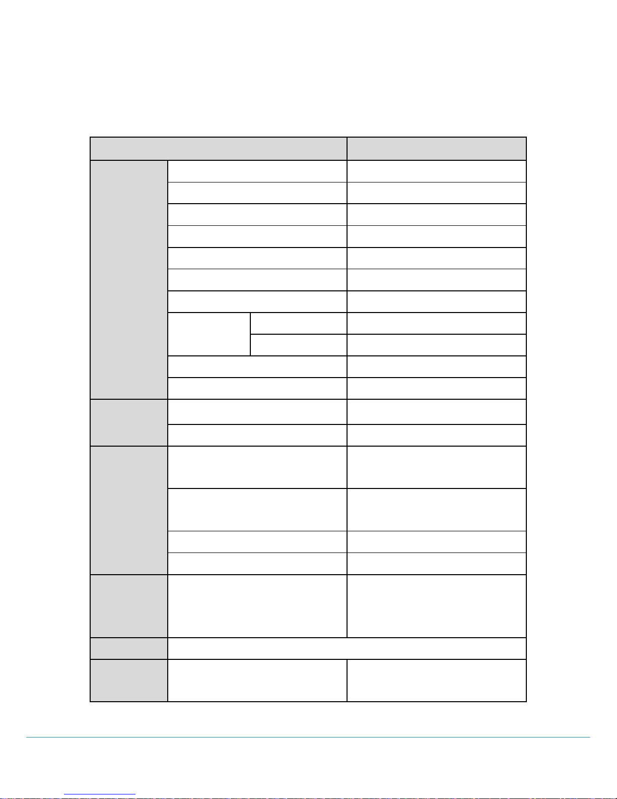
3-1 Specification
Content
Specification
Performance
External Resolution
1/20,000
Internal Resolution
1/2,097,152 (±1,048,576)
Input Sensitivity
0.1µV/V
Max. Signal Input Voltage
3.2 mV/V
Load cell Excitation
DC +5V
A/D Conversion Method
Sigma-Delta
Decimal Point
0, 0.0, 0.00, 0.000
Drift
Offset
10PPM/℃
Span
10PPM/℃
Linearity
0.001% of Full Scale
Analogue Sampling(sec)
60times / sec
Environment
Operating Temperature Range
-10℃ ~ +40℃ [14℉ ~ 104℉]
Operation Humidity Range
40% ~ 85% RH, Non-condensing
Function
Calibration Mode
Test Weight Calibration Mode
Simulation Calibration Mode
Display
6 digit, 15mm(0.6inch)
Red Color FND
Key Pad
5EA Standard Key
Additional Digital Input
2pcs addable
Comm
Serial Interface(RS-422/485)
Data Transference
Command Mode
Serial Printer Mode
Power
Input Power DC 24V Power Consumption MAX 8W
Size
96mm(W)ⅹ48mm(H)ⅹ135mm(D)
Including Connector
Weight : 300g

6
SI 480E DIN SIZE WEIGHING CONTROLER
3-2. Front Panel
3-2-1 Front Panel (Display / Key Pad)
3-2-2. State Lamp
STEADY
When the weight is “STEADY”, Lamp is ON.
ZERO
When the current weight is ”ZERO”, Lamp is ON.
TARE
“TARE” function is set, Lamp is ON.
HOLD
“HOLD” function is set, Lamp is ON.
TxD
When the Indicator transmits Serial communication data (Print data),
Lamp is ON.
RxD
When the Indicator receives Serial communication data, Lamp is ON.
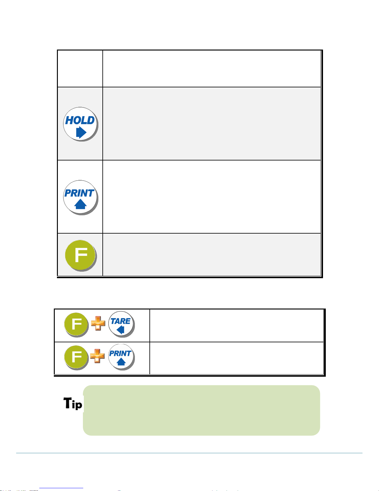
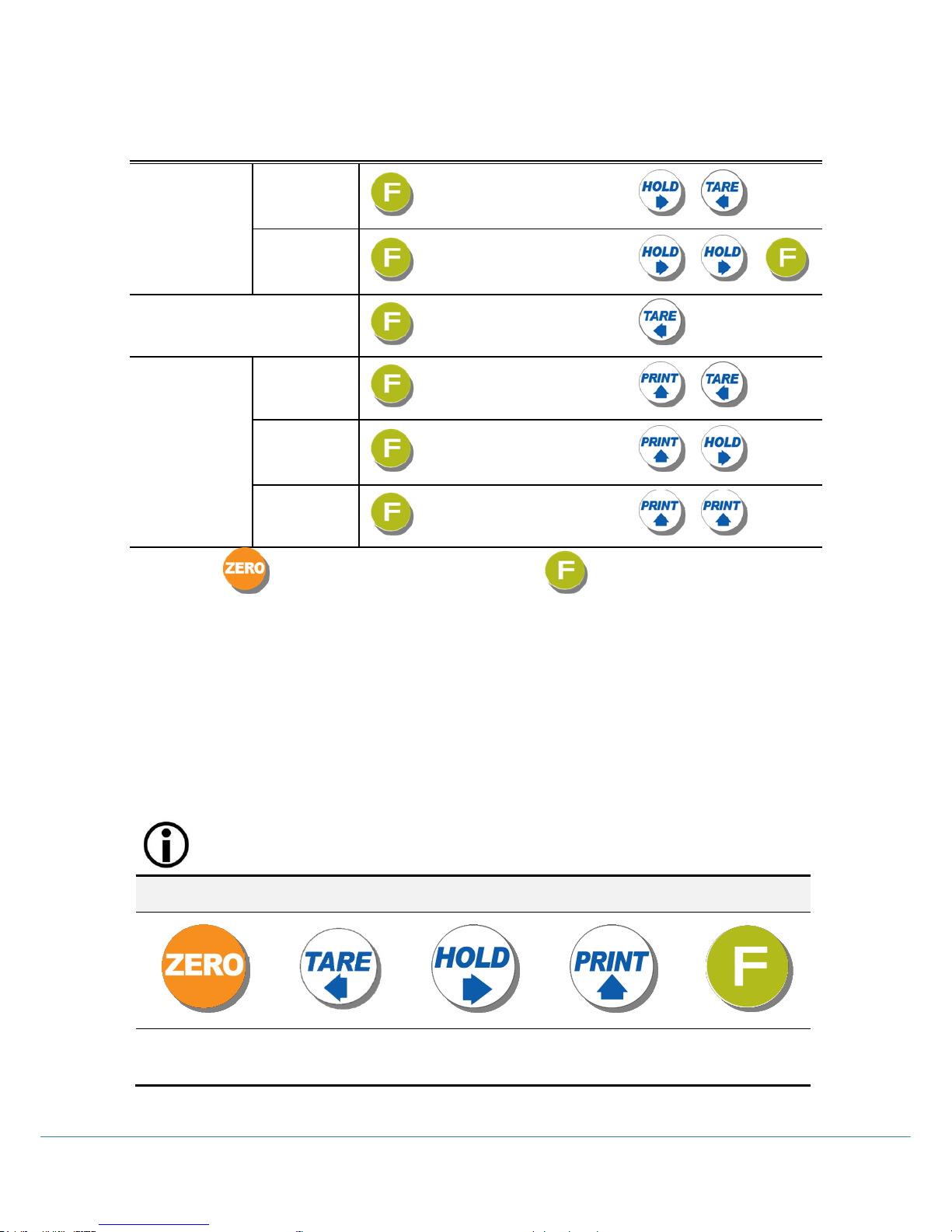
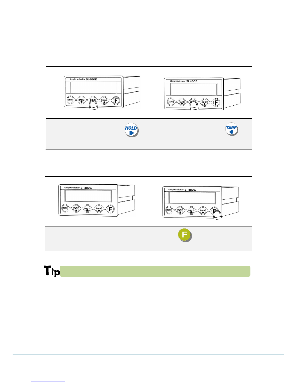
3-2-3. Key Operation
1. Normal Mode : Make Weight value as Zero. (F07, F08 setting)
2. Calibration Mode : Cancel the value or move to previous step.
3. F-Function setting : Cancel / ESC
4. Set point setting : Cancel / ESC
5.Test Mode 1 : Cancel or ESC
6.Test Mode 2 : Cancel or move to previous step
7.Set up Mode : Cancel
1.Normal Mode : Set the TARE Function .(F09 setting)
1st input : “TARE”, 2nd input : “TARE Reset”
(When “HOLD” or weight value is ZERO, then this key doesn’t work.)
7
SI 480E DIN SIZE WEIGHING CONTROLER
2.Calibration Mode : Move to left
3.F-Function setting : Move to left
4.Test Mode 1 : Analog value check mode
5.Set up Mode : Enter F-FUNCTION Mode
1. To set the “HOLD” Function (refer F10) [1st input : “HOLD”, 2nd input : “HOLD
Reset” ]
2.Calibration Mode : Move to right
3.F-Function setting : Move to right
3. Under “SETUP” Mode, Enter into the “Calibration” Mode.
4.Test Mode 1 : Analog Variation value check mode
5.Set up Mode : Enter Calibration Mode.
※ Under HOLD setting first digit shows “H”
1. Normal Mode : Print out (refer F38, F32)
2.Calibration Mode :Increase set value
3.F-Function setting : Increase set value
4.Test Mode 1 : Key/Digital Input check mode
5. Set up Mode : Enter Test Mode.
※ If the printer is installed, under “F01-01 setting, when you press this key the current
valued is increased. And the current weight is saved and print out, altogether. (Refer to
CH.5-4)
1. Press this key 4times, within 2secs, enter “SET-UP” mode.3.F-Function setting : Save
the value go to next step
4.Test Mode 1 : Standard serial interface test mode
5.Set up Mode : Set point setting Mode.
●Setup Mode :It is a mode can SET UP the calibration, Function of SI480E .(refer to CH5. SET UP)
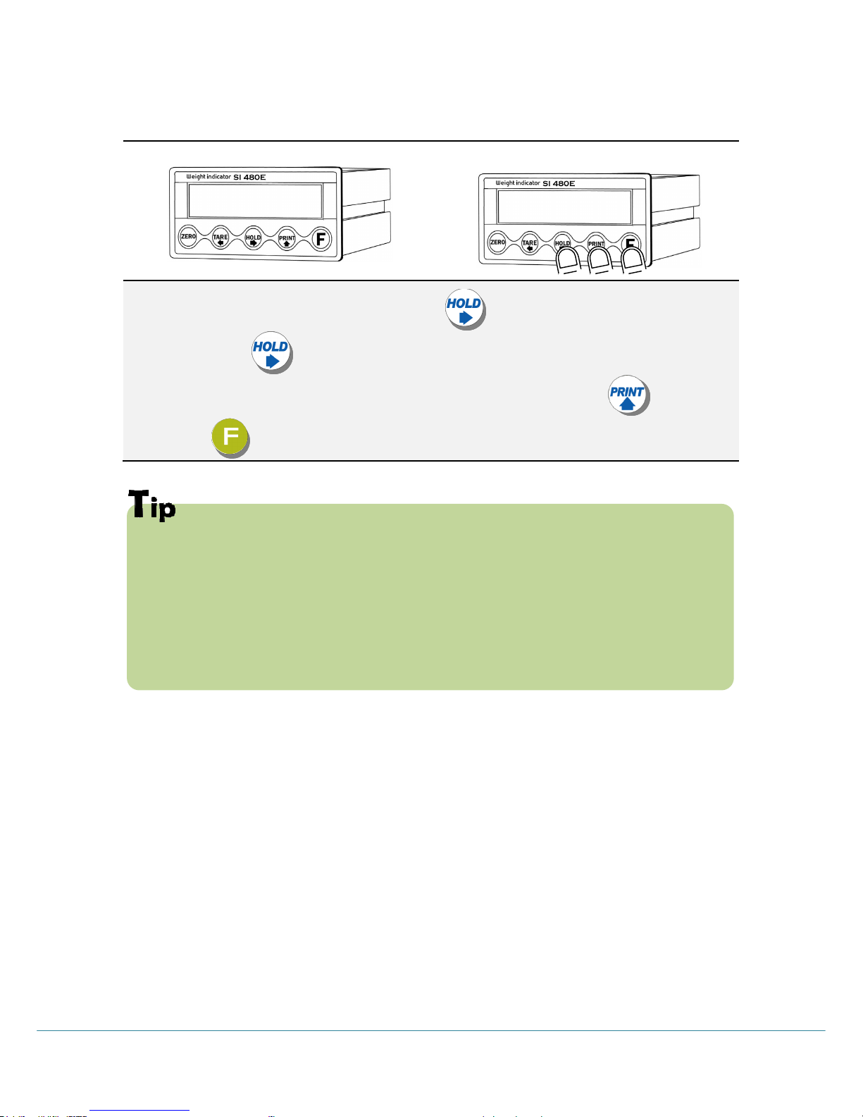
3-2-4. Hot key (with F key)
Continuous “TARE” setting
(From the second TARE setting, use this key)
If the Printer is installed,
You can print out the “Grand-total data”.
(GRAND-total data can be checked though Print output).
Max. accumulated weighing count : 999,999times
Over 999,999times return to “0” time
Max. accumulated weight display : 999999999 (g, kg, ton)
Over 999,999,999 (g, kg, ton) return to “0” (g, kg, ton)
8
SI 480E DIN SIZE WEIGHING CONTROLER
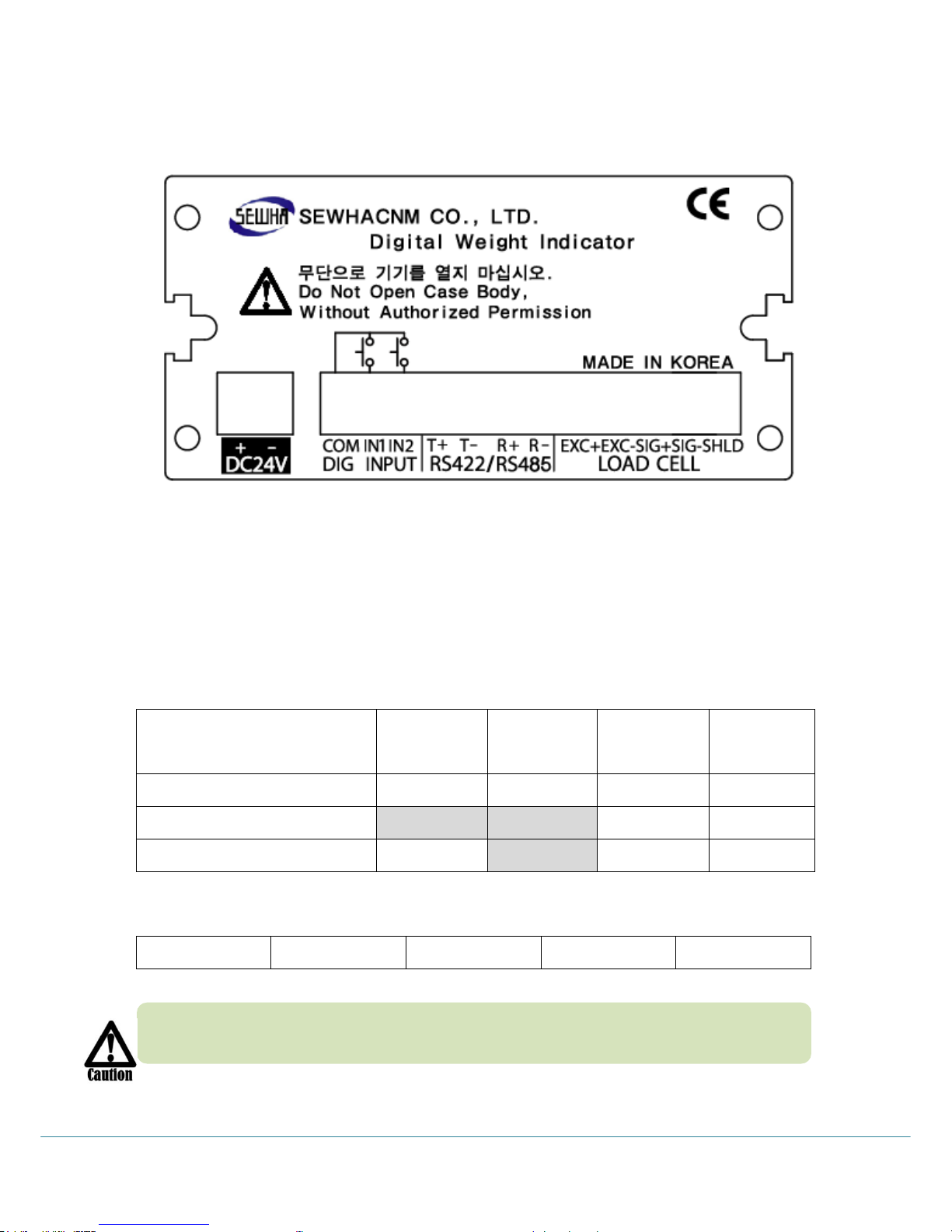
3-3 Rear Panel
1.POWER 2.INPUT 3. SERIAL I/F 4.LOAD CELL
1. Power DC IN: 24V (Power : 24V 1A recommended)
2. External Input terminal: Standard tow port (Refer to F-Function F14, F15 to select
desired function of each input terminals )
3. Serial Interface terminal : Stand serial port is RS485
Communication Method
TX+
Terminal
TX-
Terminal
RX+
Terminal
RX-
Terminal
RS – 422(Standard)
TX+
TX-
RX+
RX-
RS – 485(Standard)
Not used
Not used
RTX +
RTX-
RS – 232(Odering spec)
GND
Not used
TX
RX
4. Load cell Input
EXC+
EXC-
SIG+
SIG-
SHIELD
Please check the Comm. and other specification in the label, attached on the cover
plate first, and make connection according to that information.
9
SI 480E DIN SIZE WEIGHING CONTROLER
4. INSTALLATION
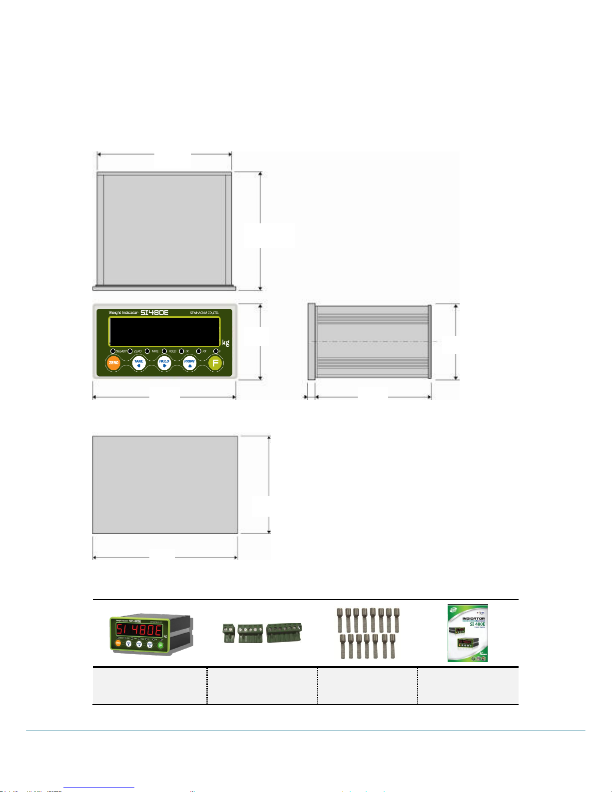
4-1. External Dimension & Cutting Size
External Dimension (unit: mm)
Cutting Size (unit : mm)
4-2. Installation Components
SI480E
Connector (3EA)
3P, 5P, 7P
Pin terminal(15EA)
User Manual
91
118
48
96
44
116
2
45
93
51480e
10
SI 480E DIN SIZE WEIGHING CONTROLER
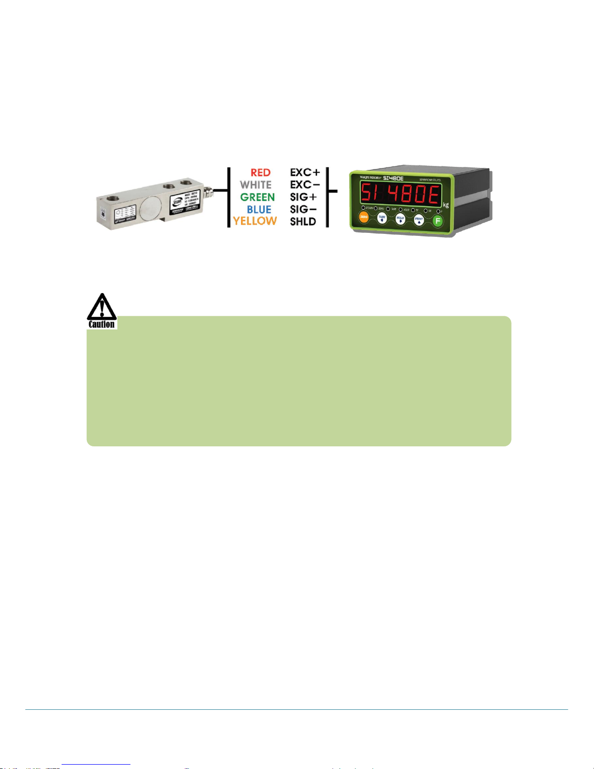
4-3 Load cell Installation
Load Cell Wire Connection (In case of SEWHACNM’s Load cell)
It depends on the manufacturer of load cell, please check the specification.
※ Load cell wire color can be changed without prior notice.
Under set up the Load cell, if EXC+ and EXC- have a short circuit,
It may cause damage in the indicator.(specially analogue board)
If you connect other wires to Load cell terminal wrongly, it may cause
damage in the analogue board.
Before connecting the load cell cable you have to power off and be sure to
connect the cable to the terminal correctly.
Do not weld near the load cells , Indicators or other devices.
Load Cell Installation
1. You can connect Max. 8pcs of same capacity Load cells at once. (350 Ω)
2. You have to make horizontal balance on the ground.
3. If you install more than 2pcs of load cells, use Summing box and adjust output signal
difference as minimum. It can make wrong weighing process caused by each load cell’s
variation.
4. If there is some temperature difference around Load cell, it can cause wrong weight
measurement.
5. Don’t do Welding job or Arc discharge around installation place. But, there is no
choice, please disconnect power cable and Load cell cable.
6. If you measure static electricity material, please make earth between down part and
up part of Load cell.
-----Sewhacnm Co.,ltd. Load cell & wire color----

11
SI 480E DIN SIZE WEIGHING CONTROLER
5. SET-UP
5-1. Set up mode
This is the Menu which can set the all of the functions.
There may be some display differences between real and on the manual.
5-1-1. Start “SET UP” Mode (Pass Word Not use)
Press key four times within 2sec
When “SET UP” is displayed, SETUP Mode is activated
5-1-2. Start “SET UP” Mode (Pass Word Use – Refer F-function 95)
Press key four times within 2sec
If “P-W” displays, input 4 chracters password.
If Password is right, “SETUP” Mode starts.
If Password is wrong, it is back to weighing display.
If you set password by “F95”. “TEST” mode, you cannot start “SETUP” Mode
without password. Please don’t forget the pass word.
After starting ”Calibration” mode, and “Test” mode, serial I/F will be closed.
After initialization (F77) the password is .
51480e
5et-Up
51480e
p-Uj
5et-Up
0.000
12
SI 480E DIN SIZE WEIGHING CONTROLER
To Go Each Mode
Calibration
Weight
Calibration
key 4 times (Pass word)
Simulation
Calibration
key 4 times (Pass word)
F-FUNCTION Mode
key 4 times (Pass word)
Test Mode1
Analog Value
key 4 times (Pass word)
Analog
difference
key 4 times (Pass word)
Key test
key 4 times (Pass word)
Entering means ESC/UPPER step, Entering means SAVE/NEXT Step.
■ Adjusting “ZERO” Balance (Calibration)
Adjust weight balance between “Real weight” on the load cell(Weight Part) and
“Displayed weight of Indicator”. When you replace LOAD CELL or Indicator, you
have to Calibrate process once again.
(When you start calibration mode, TARE, HOLD & PRINT will be reset.)
Before processing calibration, please warm up the indicator during 15
min to guarantee more preciseness.
Calibration Key
CANCLE/BACK
Move to left
Move to right
Increase set value
Save and Move
to next step
13
SI 480E DIN SIZE WEIGHING CONTROLER
5-2 Test Weight Calibration Mode (Using test weight)
5-2-1. Start Test Weight Calibration Mode
Under “SETUP” displays then Press key.
When “CALIBR” displays, press key,
Then Test Weight Calibration Mode starts.
※ If you set password through “F95”, you have to input the pass word.
5-2-2. Setting “Capacity of weighing Scale”
After displaying “CAPA”, input max capacity with keys & Press key to save & move to next
step.
If you want that set Max capa is 1,000kg, then just input “1000”.
Cal1br
5et-Up
Capa
1000
14
SI 480E DIN SIZE WEIGHING CONTROLER
5-2-3. “Decimal Point” and “Digit / Division” Value
After “DIVI” is displayed select Decimal point with key.
Whenever pressing key , decimal point will be changed.
Please stop at the optimal position. And select Division optimal division with key.
Finally press key to save and move to next step.
Max. Decimal point will be 0.001, and digit can be selectable among
1, 2, 5, 10, 20, 50.
Digit and Decimal point must be fulfill the below condition.
- (Max. capacity value / division value) cannot be over than 20,000.
If this condition is not fulfilled, “err-1” will be displayed and move back to
Capacity setting mode.
diui
0.1
 Loading...