

Sewha SI 4410 Operation Manual
Digital Weighing Indicator
Model : SI 4410
Operation Manual
Version 1.21 (2007. 9)

CONTENTS
1. Before Installation
1-1. Caution / Warning Marks
1-2. Other Marks
1-3. Copy Rights
1-4. Inquiries
2. Introduction
2-1. Introduction
2-2. Cautions
2-3. Features
3. Specification
3-1. Analog Input & A/D Conversion
3-2. Digital Parts
3-3. General Specifications
3-4. Option Cards
3-5. Front Panel (Display & Key pad)
---------------
---------------
---------------
---------------
---------------
---------------
---------------
---------------
---------------
---------------
---------------
---------------
---------------
---------------
---------------
---------------
---------------
4 page
4page
4page
4page
4page
4page
5 page
5 page
5 page
5 page
5 page
6 page
6 page
6 page
7 page
7 page
7 page
3-6. Rear Panel
4. Installation
4-1. External Dimension & Cutting Size
4-2. Assembly
4-3. Load Cell Installation
5. Set-up
5-1. Calibration
5-2. TEST Weight Calibration Mode
5-3. Simulation Calibration Mode(Without Test Weight)
5-4. Set-up
5-5. F-Function List
5-6. F-Function
---------------
---------------
---------------
---------------
---------------
---------------
---------------
---------------
---------------
---------------
---------------
---------------
12 page
13 page
13 page
14 page
15 page
18 page
18 page
18 page
22 page
26 page
27 page
30 page
- 2 -

6. Interface
---------------
68 page
6-1. Serial Interface (RS-232C)
6-2. Current Loop Interface
6-3. Print Interface (Option 01 : Centronics Parallel Interface)
6-4. Analog Output Interface (Option 02 : 0~10V)
6-5. Analog Output Interface (Option 03 : 4~20mA)
6-6. Serial Interface (Option 04 : RS-232C / 422 / 485)
6-7. BCD INPUT (Option 05)
6-8. Command Mode
7. Error & Treatment
7-1. Load Cell Installation
7-2. Calibration Process
7-3. Indicator Error & Treatment
7-4. Indicator Test Mode
Warrantee Certification
---------------
---------------
---------------
---------------
---------------
---------------
---------------
---------------
---------------
---------------
---------------
---------------
---------------
--------
68 page
71 page
72 page
74 page
75 page
76 page
77 page
78 page
84 page
84 page
85 page
86 page
87 page
89 page
- 3 -
1. BEFORE INSTALLATION
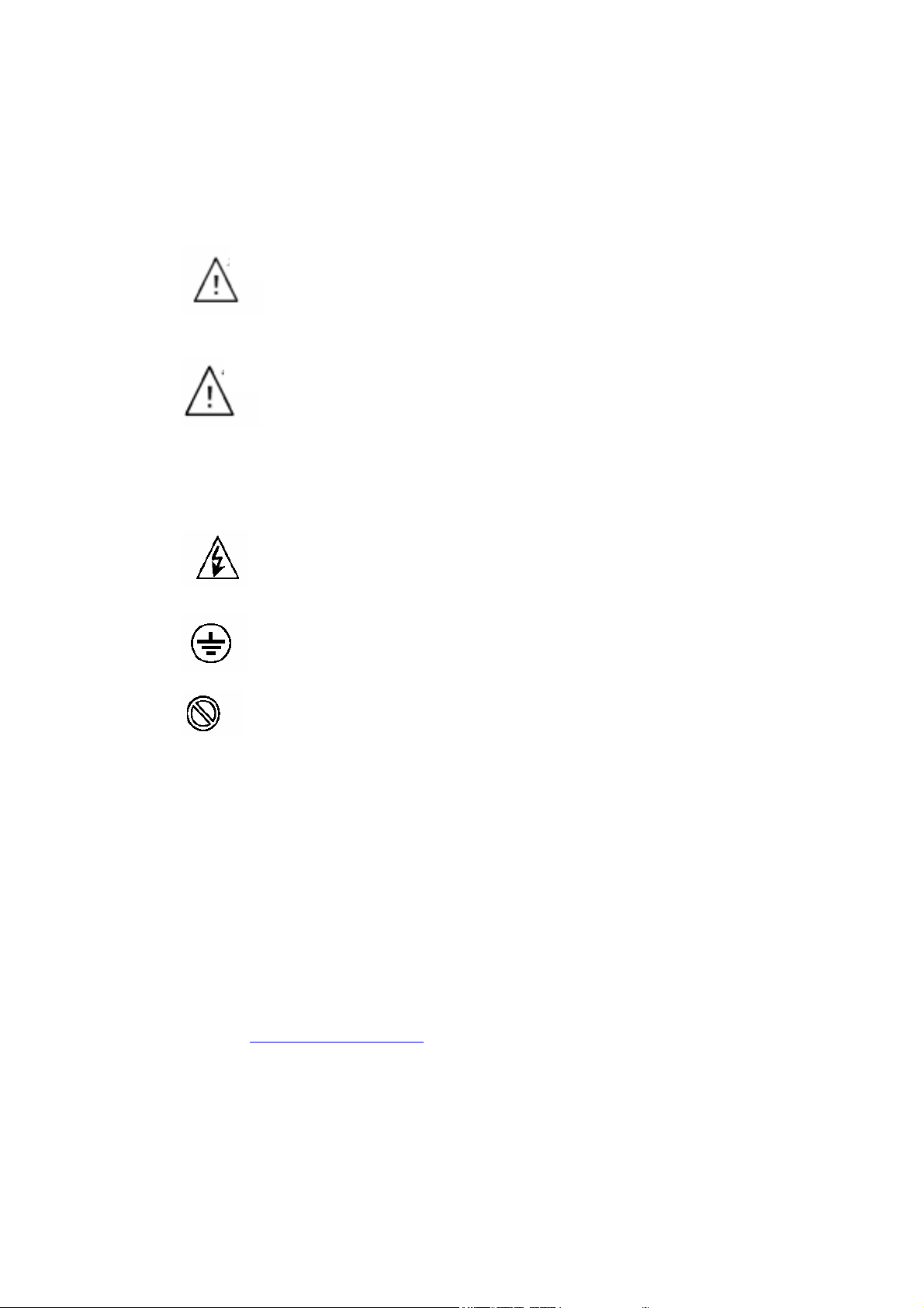
1-1. Caution / Warning Marks
Warning
This mark warns the possibility to arrive death or serious injury in case
1-2. Other Marks
Caution
of wrongly used.
This mark cautions the possibility to arrive serious human body injury
or product lose in case of wrongly used.
Warning for Electric Shock or Damage.
Please do not touch by hand
Protective Ground(Earth) terminal
Prohibition of Operation process
1-3. Copy Rights
1). All Right and Authority for this Manual is belonged to Sewhacnm Co.,Ltd.
2). Any kinds of copy or distribution without Sewhacnm Co.,Ltd’s permission will be prohibited.
1-4. Inquiries
If you have any kinds of inquiries for this model, please contact with your local agent or Head
Office.
Head Office : Sewhacnm Co.,Ltd.
Website : http://www.sewhacnm.co.kr
Email : sales@sewhacnm.co.kr
- 4 -

2. INTRODUCTION
2-1. Introduction
Thank you for purchase this “SI 4410” Industrial Digital Weighing Controller.
This “SI 4410” model is advanced model of “SI 3200”, with powerful communication performance.
With 2ports serial port interfaces and precise weighing control system, you can upgrade your
weighing process.
This “SI 4410” Weighing Controller has various kinds of “Weighing Mode”, like Limit, Packer, Loss-
in Weighing(Minus Limit), so you can apply various kinds of weighing application.
Enjoy your process with “SI 4410” Weighing Controller.
2-2. Cautions
1). Don’t drop on the ground or avoid serious external damage on item.
!
Cautions
2). Don’t install under sunshine or heavy vibrated condition.
3). Don’t install place where high voltage or heavy electric noise condition.
4). When you connect with other devices, please turn off the power of item.
5). Avoid from water damage.
6). For the improvement of function or performance, we can change item specification without prior
notice or permission.
7). Item’s performance will be up-dated continuously base on previous version’s performance.
2-3. Features
1). All Modules and Option Cards are isolated to maximize accuracy and performance.
2). Self diagnose function
3). External input terminal inside.(4pcs:Can be set by F11 mode)
4). By using “Photo-Coupler” on each module(Option, Analog board, In/Out), we improved “Impedance
problem”, “Isolation ability among inputs”, “Leading power problem”, and “Noise covering function”.
5). Data back-up function, when the sudden power off.
6). “Set value Error” check function added. – Check “Set values for each weighing mode”.
- If there is any wrong set value, “E” will be display and will not start weighing process
7). Polycarbonate film panel, strong for dust and water.
8). Weight Unit selection Function added. (“g”, “kg”, “t” selectable – F40)
10). Variable options(Order in advance, Refer Chapter 6. Interface) – “RS-232C” Standard installed.
11). Improved “Automatic Free Fall(In-flight) Compensation” function added. – Suitable for
“Liquid Filling” system (Can compensate “minus” weight)
12) 2port Serial Interface available – various applications (monitoring, printing, and Command
mode) are available.
- 5 -
3. SPECIFICATION
3-1. Analog Input & A/D Conversion
Input Sensitivity
Load Cell Excitation
Max. Signal Input Voltage
Temperature Coefficient
Input Noise
Input Impedance
A/D Conversion Method
A/D Resolution(Internal)
A/D Sampling Rate
Non-Linearity
Display Resolution(External) 1/20,000
3-2. Digital Part
Display Parts Specification
7Segments, 7digits VFD green Color
Main Display
Size :12.7(H) ×7.0(W)mm
DC 10V ( - 5V ~ + 5V )
[Zero] ±16PPM/℃
[Span] ±3.5PPM/℃
520,000 Count(19bit)
Max. 500times / Sec
0.2㎶ / Digit
Max.32mV
±0.3㎶ P.P
Over 10㏁
Sigma-Delta
0.005% FS
Display
Status lamp
K e y
Sub-Display
Min. Division ×1, ×2, ×5, ×10, ×20, ×50
Max. display value +999,950
Under Zero value "-" (Minus display)
Steady, Zero, Tare,
Run, Gross, Print,
Comm.
kg, g, t /
FINAL, PRE1, PRE2
Number, Function,
CAL. Lock Key
7Segments, 6digits FND, Red Color
Size : 9.2(H) ×4.8(W)mm × 4pcs
" ▼" Condition display Lamp
Red / Yellow-Green LED Display(3Ø)
Number Key, Function, CAL. Lock key (14pcs)
- 6 -
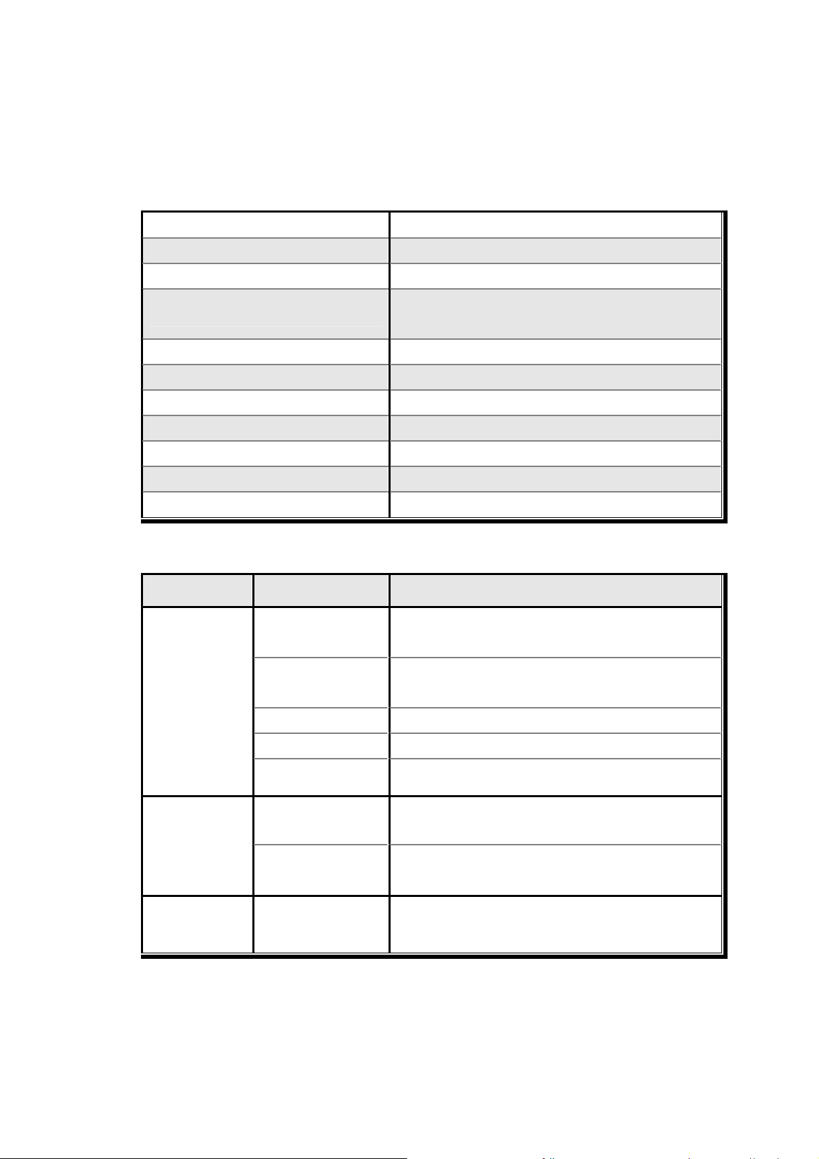
3-3. General Specification
Power Supply
Operating Temperature Range
Operating Humidity Range
External Dimension
Net Weight(kg)
Gross Weight(kg)
※ AC 110V, Power supply is an optional before ex-factory.
AC110/220V(±10%), 50/60Hz, about 30VA
-10 ~ 40℃℃
Under 85% Rh (non-condensing)
200mm(W)x105mm(H)x165mm(L)
About 2.3kg
About 3.0kg
3-4. Option Card
Option No.1
Option No.2
Option No.3
Option No.4
Option No.5
※ Serial Interface (RS-232C) or Current Loop is Standard installed.
In the Optional Serial port, there is no Current Loop function
Printer Interface : Centronics Parallel
Analog Output (0~10V or 0~5V)
Analog Output (4~20mA)
Serial Interface : RS-232C / 422 / 485
BCD INPUT (P/N change purpose)
Weight Display
Status Lamp
Function key
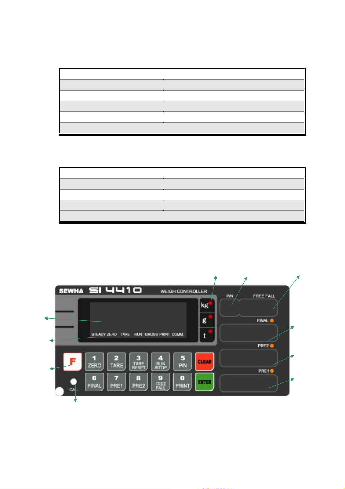
3-5. Front Panel (Display / Key Pad)
Weight Unit LED Part No. Free Fall Set value
Final Set value
(weighing count)
PRE2 Set value
(Total Weight)
PRE1 Set value
(Total Weight)
Calibration Lock S/W
※ Through the “Front display”, you can check various weighing information, like weight unit, each set
value, relay output, accumulated weight of each P/N or all P/N.
- 7 -
3-5-1. Status Lamp (ANNUNCIATORS) : “▼” Lamp is “ON”.
Steady
Zero
Ta re
Run
Gross
Print
Comm.
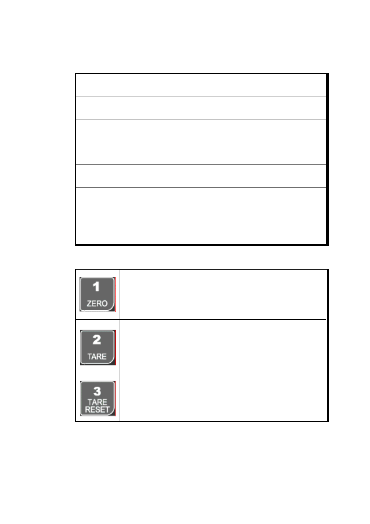
3-5-2. Key Operation
When the weight is Steady, “▼” Lamp is turn on.
When the current weight is Zero, “▼” Lamp is turn on.
(Displayed weight is Zero, “▼” Lamp is turn on.)
Tare function is set, “▼” Lamp is turn on.
(Tare Reset Æ “▼” Lamp is turn off.)
Weighing Batch is started, “▼” Lamp is turn on.
When display Gross weight(Net weight + Tare Weight), “▼” Lamp is turn on.
(Under F19-01 setting)
When print key input or Auto print, “▼” Lamp is turn on.
When indicator transfers or receives data from other devices, “▼” Lamp is turn
on. (If the “▼” is off although there is some data transference, please check
communication settings).
Make Weight value as Zero.
Under F08, you can set the Zero key operation range, as 2%, or 5%, or 10%, or
20% of Max. Capacity.
※ Under “Tare” key input, Zero key will not be activated.
Make Weight value as Zero, including Tare Weight.
Under F09, you can set the Tare key operation range, as 10%, 20%, 50%, or
100% of Max. Capacity.
Tare setting : Under F10-00 setting, “TARE” key input
Under F10-01 setting, “Tare”+ No. key + “Enter”
Remove set TARE value.
- 8 -
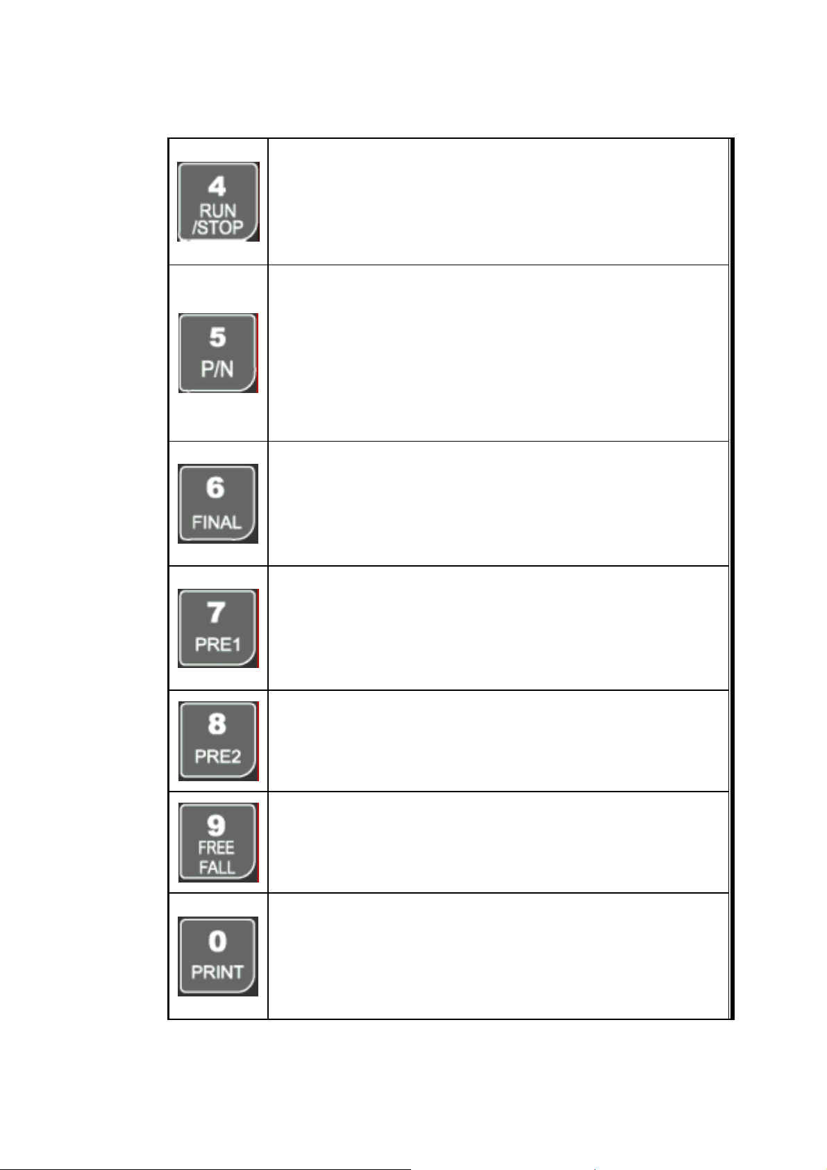
1. To START or STOP weighing process.
First input, SI 4410 Controller Starts weighing process, and Second input, SI
4410 Controller stops weighing process.
This function will be activated under F21※ -02, 04, 05, 06, 07 setting, only.
You can set each weighing process as a certain P/N.
Each weighing process will be saved with FINAL, PRE1, PRE2, and Free Fall
set value.(Max. 50 kinds of P/N you can set)
And you can call certain P/N with each set value.
P/N save : Choose certain P/N and input FINAL, PRE1, PRE2, and Free
Fall value and save.
P/N call : P/N + Number key + Enter
Set Target weight of each P/N. (Refer F21 weighing mode)
※ Each weighing mode has different concept of FINAL value.
FINAL value set : Final + Number key + Enter
FINAL value check : Press FINAL Æ Display during 5sec
Set PRE1 weight of each P/N. (Refer F21 weighing mode)
※ Each weighing mode has different concept of PRE1 value.
PRE1 value set : PRE1 + Number key + Enter
PRE1 value Check : Press PRE1 Æ Display during 5sec
Set PRE2 weight of each P/N. (Refer F21 weighing mode)
※ Each weighing mode has different concept of PRE2 value.
PRE2 value set : PRE2 + Number key + Enter
PRE2 value Check : Press PRE2 Æ Display during 5sec
Set Free Fall value and control FINISH relay in advance.
(Refer F20 Free Fall setting)
Free Fall value setting : Free Fall + Number key + Enter
Free Fall value check : Press Free fall Æ Display during 5sec
1. Manual Print (F38-00 setting, under F35-01)
2. Manual weighing Data save for accumulated weighing count and weight.
(F01-00 / 02 setting)
3. Calibration mode
- Digit setting
- 9 -
Whenever pressing “0”key, digit will be change 1, 2, 5, 10, and 50.
- Decimal point position
Whenever pressing “0”key, decimal point will be change.
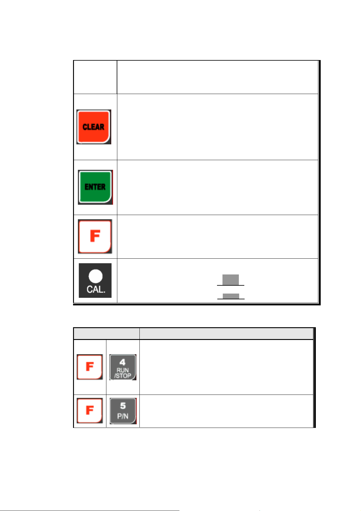
1. Modify the set value during setting process.
2. Calibration mode
- Move back to previous step.
F-function Mode.
- F-function Exit : Press “Clear” key, once.
- F-Test Mode Exit : Press “Clear” key, twice.
1. Save set value during setting process.
2. Calibration mode
- Save current setting and move to next step.
3. F-Function mode
- Save current F-function setting, and move to next F-function
1. “F-TEST” Mode Entrance : Press “F” key for 5sec.
2. Under “F-function Mode”, Move to next Function or move to certain function
No.(Press function No. and press “F” key)
3. Function key (Refer “Function keys”)
Enter/Exit to “Calibration” mode.
“ON” : Enter to Calibration Mode.
“OFF” : Exit from Calibration Mode.
※ Function Keys (Combined Key functions)
Function Key Contents
Manual Discharge
If there are not enough material to process one weighing process in
the scale, you can discharge the remained material with this function.
(Only for F21-02, 04, 05, 06, 07 mode)
Please refer “F29” for more information.
Print all P/Ns’ accumulated weighing count and weight.
(Grand-Total Print)
- 10 -
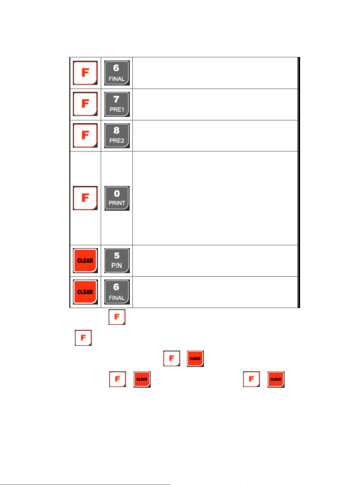
Print current P/N’s accumulated weighing count and weight.
(Sub-Total Print)
Set “Over N.G”(Error relay) range.
(If you set larger value than FINAL value, the setting is not saved)
Set “Under N.G”(Error relay) range.
(If you set larger value than FINAL value, the setting is not saved)
Display accumulated weighing count and weight
Max. accumulated weight display : 21,474,839,647(g, kg, ton)
- Over 21,474,839,647(g, kg, ton) Æ return to “0”(g, kg, ton)
Max. accumulated weighing count : 999,999times
- Over 999,999,999times Æ return to “0”times
Under F15, you can set what kinds of accumulated count and ※
weight.
- F15-00 : Display current P/N’s accumulated count and weight.
- F15-01 : Display all P/Ns’ accumulated count and weight
Delete all P/Ns’ accumulated weighing count and weight
(If you set F44-01, the data will be automatically deleted after
※ After Pressing key, you have to input above function keys within 5sec. - After 5sec, the
key activation is loose
※ If you set “F51-01” you can check the
※ After Pressing “
activation will be loose.
“Grand-Total Print).
Delete current P/N’s accumulated weighing count and weight
(If you set F44-01, the data will be automatically deleted after “Sub-
Total Print).
/ key activation through Main display.
”/ “ ” key, non-function keys are input, the “ ”/ “ ” key
- 11 -
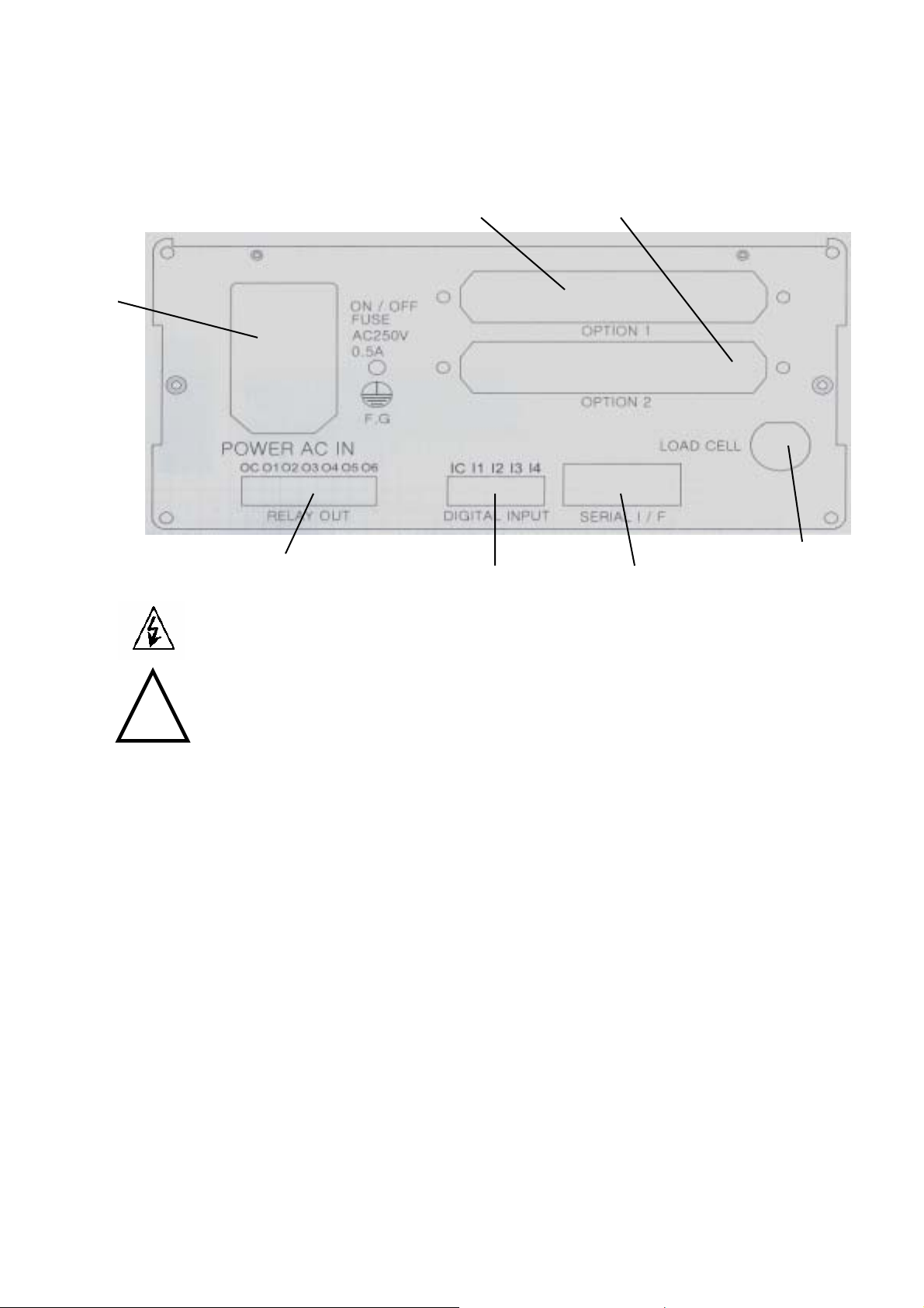
AC Power Input
3-6. Rear Panel
Option Card(1) Option Card(2)
!
Warning
Relay Output Terminal
① POWER AC IN
- Power switch : Power on/off switch.
- Fuse : AC250V / 0.5A , φ5.25 , 20mm.
- AC IN : Available Input AC 110V / 220V.
The standard power supp※ ly is AC 220V(Fixed when ex-warehouse), if you want to have
AC 110V, please inform in advance.
Option Card 1②
③ Option Card 2
※Option Card Connector installed for Optional Interface or Output.
(Printer I/F, Analog out, RS-422/485, or RS-232C(two port)
L④ OAD CELL Connector (N16-05)
SERIAL I/F⑤
“RS-232C” or “CURRENT LOOP”(9Pin, D-Type Female) are built-in as standard
External Input : ⑥ External control input for wired remote control.
Refer to F-Function F11 to select desired function mode.
Serial Port(Standard) External Input
Load Cell Input
Input signal …………………………… Optical-Isolator
- 12 -
4. INSTALLATION
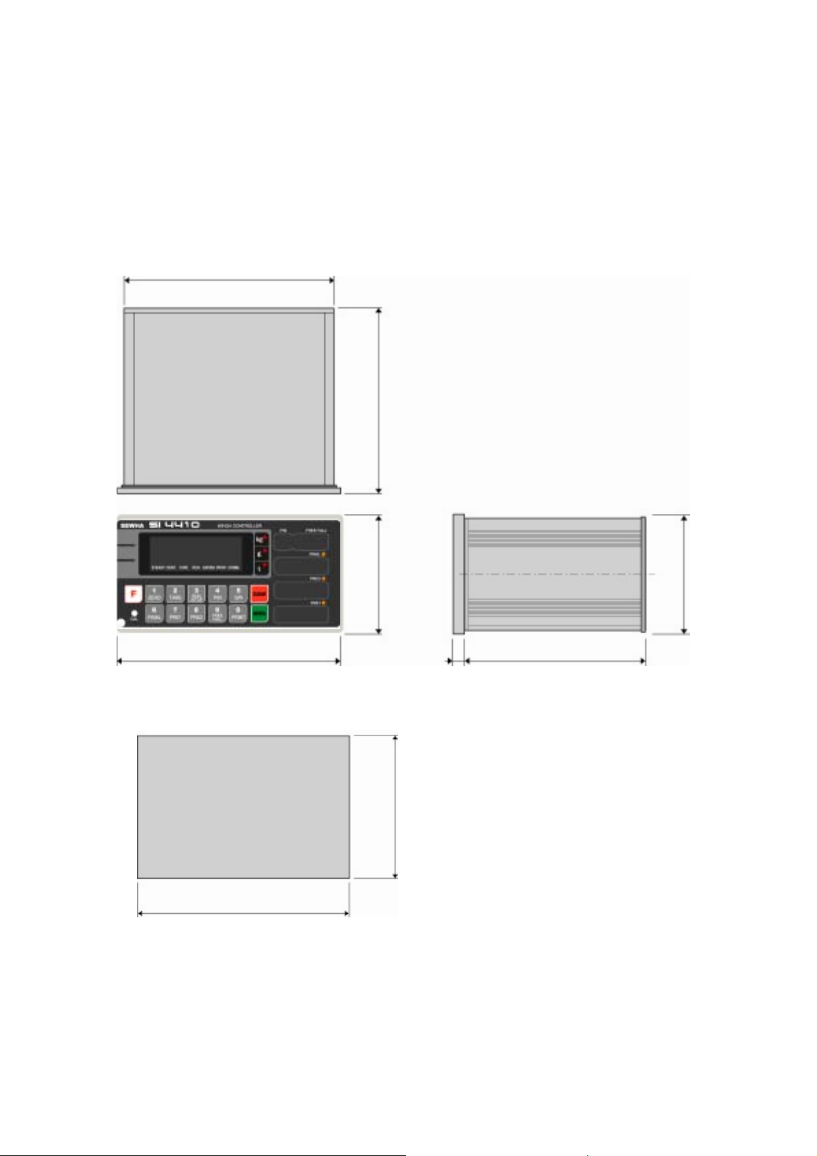
4-1. External Dimension & Cutting Size
(External Dimension) (unit : mm)
186
165
200 162.0
(Cutting Size) (unit : mm)
188
105
92
94
- 13 -
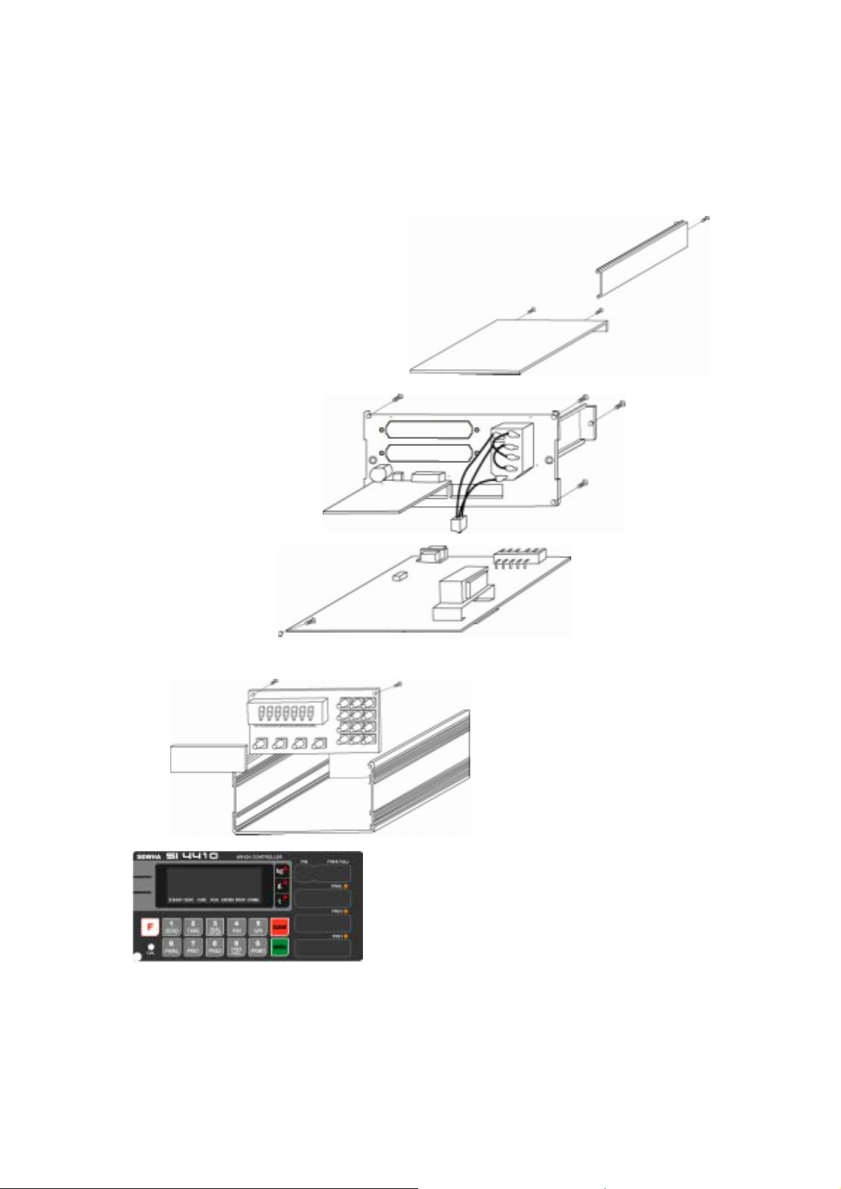
4-2. Assembly
- 14 -
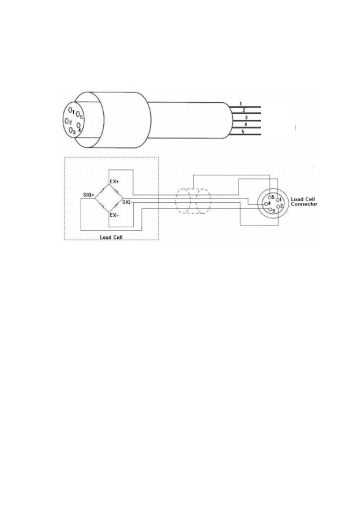
4-3. Load Cell Installation
4-3-1. Load Cell Connector Specification
Red
White
Green
Blue
Shield
4-3-2. Load Cell Installation
1). You can connect Max. 8pcs of same capacity Load cells at once. (350Ω)
2). You have to make horizontal balance on the ground.
3). If you install more than 2pcs of Load cells, use Summing box and adjust output signal
difference as minimum. It can make wrong weighing process caused by each load cell’s
variation.
4). If there is some temperature difference around Load cell, it can cause wrong weight
measurement.
5). Don’t do Welding job or Arc discharge around installation place. But, there is no choice,
please disconnect power cable and Load cell cable.
6). If you measure static electricity material, please make earth between down part and up part of
Load cell.
- 15 -
4-3-3. Load Cell Wire Connection
1). Please connect Indicator’s connector and Load cell cable basis on each color.
2). It is possible to connect Max. 8pcs same capacity load cells with parallel. (350Ω)
3). LOAD CELL Connector Standard : N16 - 05
4). The load cell cable color can be different from each manufacturer, please refer following data
sheet.
5). Load Cell Wire Color Chart (Sorted by Manufacturer)
Manufacturers EXC+ EXC- SIG+ SIG- SHIELD
Sewha CNM Red White Green Blue Black
Bongshin, CAS ,TMI ,AND Red White Green Blue Yellow(Shield)
Daesung Red Black White Green Shield
Power MNC Red White Green Black Shield
Disocell Red Blue Green White Black
Dacell Red White Green Blue Shield
BLH Green Black White Red Yellow
INTERFACE Red Black Green White Shield
KYOWA Red Black Green White Shield
P.T Red Black Green White Shield
SHOWA Red Blue White Black Shield
SHINKOH Red Black Green White Shield
TML Red Black White Green Shield
TEAC Red Blue White Black Yellow
HUNTLEIGH Green Black Red White Shield
※ Each Wire’s color specification can be changed without prior notice.
- 16 -
4-3-4. Formula to plan the precise weighing system
This “SI 4410” weighing controller’s Max. input sensitivity is 0.2㎶ / Digit.
And for precise weighing system, the following formula must be satisfied.
!
Caution
Caution : “Input sensitivity” means Min. output voltage variation of weighing part to change 1digit.
So, please do not make large input voltage to make reliable weighing system.
≤EBDⅹⅹ
Single Load cell use
Plural Load cells use
Example1.)
Number of Load cell : 1pcs
Load cell capacity : 500kg
Load cell Voltage : 2mV/V
Digit : 0.05kg
Affirmation Voltage of Load cell : 5,000mV
Max. Capacity of Weighing System : 300kg
Then, estimation result for this weighing system with formula,
0.2㎶
A
≤EBDⅹⅹ
0.2㎶
ANⅹ
A : Load cell capacity(kg)
B : Load cell Voltage(mV)
D : Digit
E : affirmation Voltage of Load cell
N : Number of Load cell
500020.05ⅹⅹ
= 1 ≥ 0.2㎶
500
Example2.)
Number of Load cell : 4pcs
Load cell capacity : 500kg
Load cell Voltage : 2mV/V
Digit : 0.10kg
Affirmation Voltage of Load cell : 5,000mV
Max. Capacity of Weighing System : 1,000kg
Then, estimation result for this weighing system with formula,
5000ⅹ2ⅹ0.10
= 0.5 ≥ 0.2㎶
500 4ⅹ
Accordi※ ng to “Resolution” or “Capacity”, it might not be calibrated like calculation.
The calculated value is larger than 0.2㎶, so this
system has no problem.
The calculated value is larger than 0.2㎶, so
this system has no problem.
- 17 -
5. SET-UP
5-1. Calibration
Adjust weight balance between “Real weight” on the load cell(Weight Part) and “Displayed weight of
Indicator”. When you replace LOAD CELL or Indicator, you have to do Calibration process once again
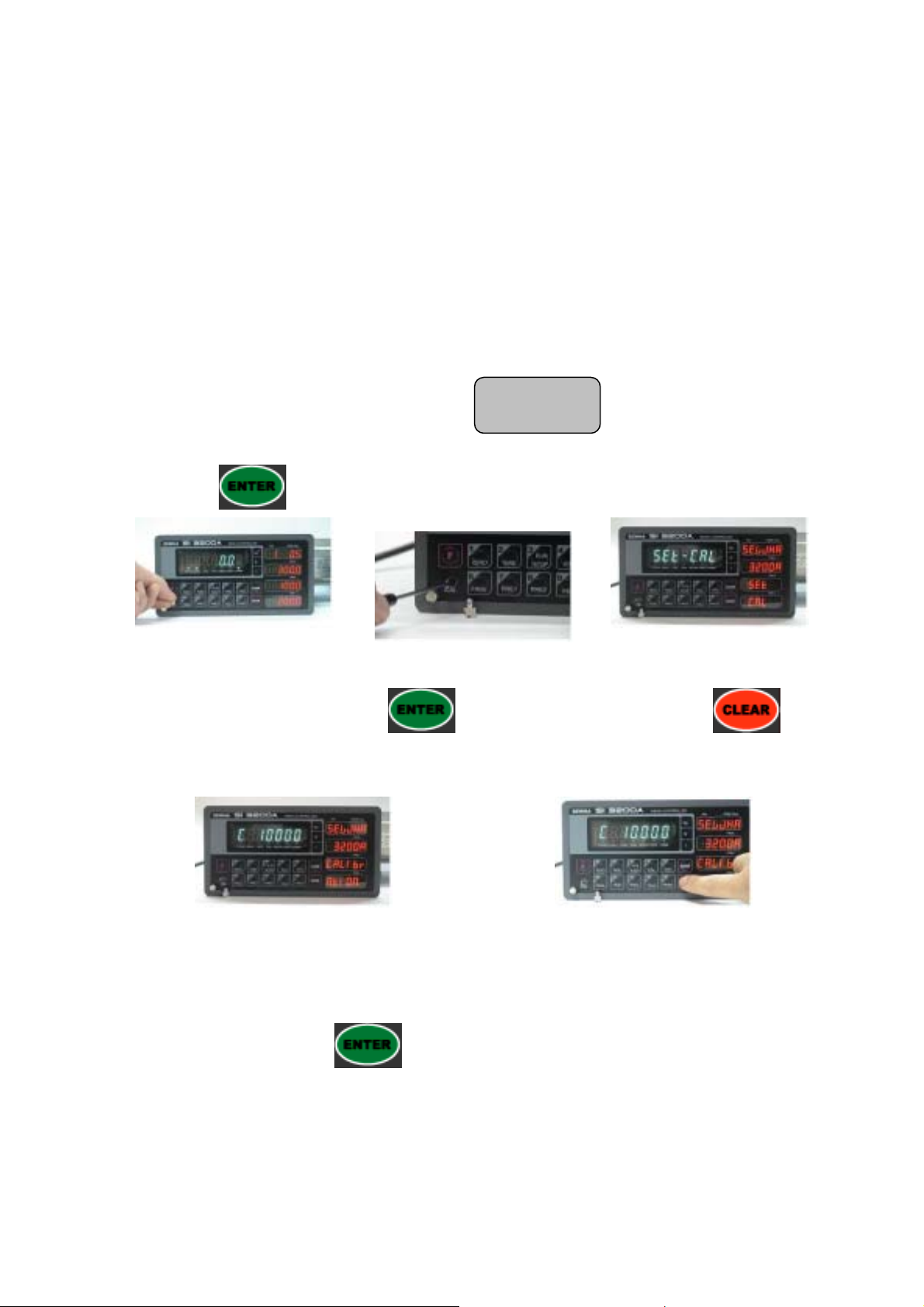
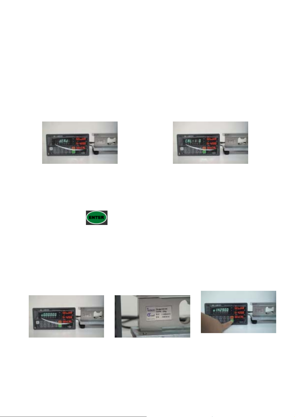
5-2. Test Weight Calibration Mode (Using Test weight)
Prepare At least 10% of Max. capacity of your weighing scale, and remove “CAL-BOLT” on the Front
panel and press “CAL - LOCK S/W” inside.
SeT-CAL
Then, you can enter the Calibration Mode with and start calibration mode with
pressing
Remove the CAL.Bolt.
※ For the save the each step, press
key.
Push the CAL. S/W
key, for the cancel or move back, press key.
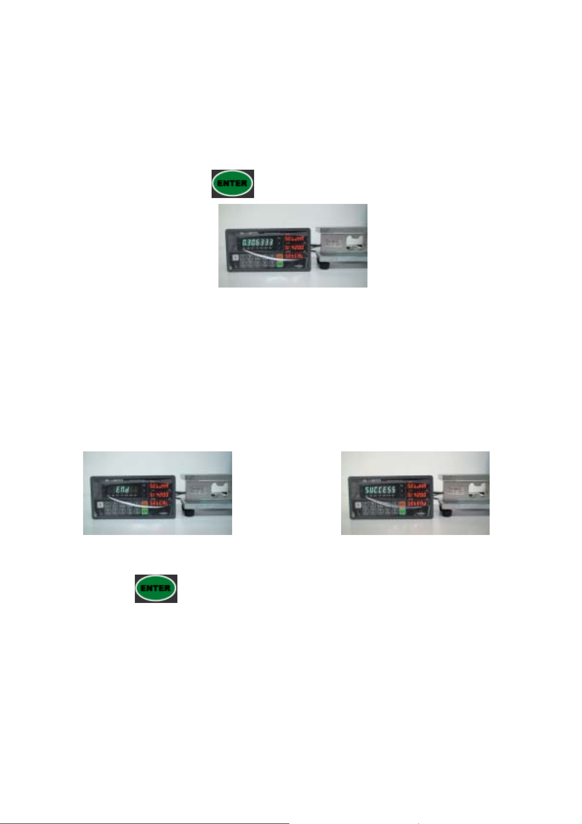
Step No.1 - Setting “Capacity of weighing Scale”.
Set Max. Capacity of Load cell
Under this step, input Max. Capacity of you weighing scale.
Check the “SET-CAL.
Massage on display.
Press “Enter” and move the next step.
Input Max. capacity of your weighing scale with No. keys.
The Max. capacity can not be exceed Max. capacity of load cell.
After finishing input, press
Step No.2 - Setting “Decimal Point”
key and save and move to next step.
- 18 -
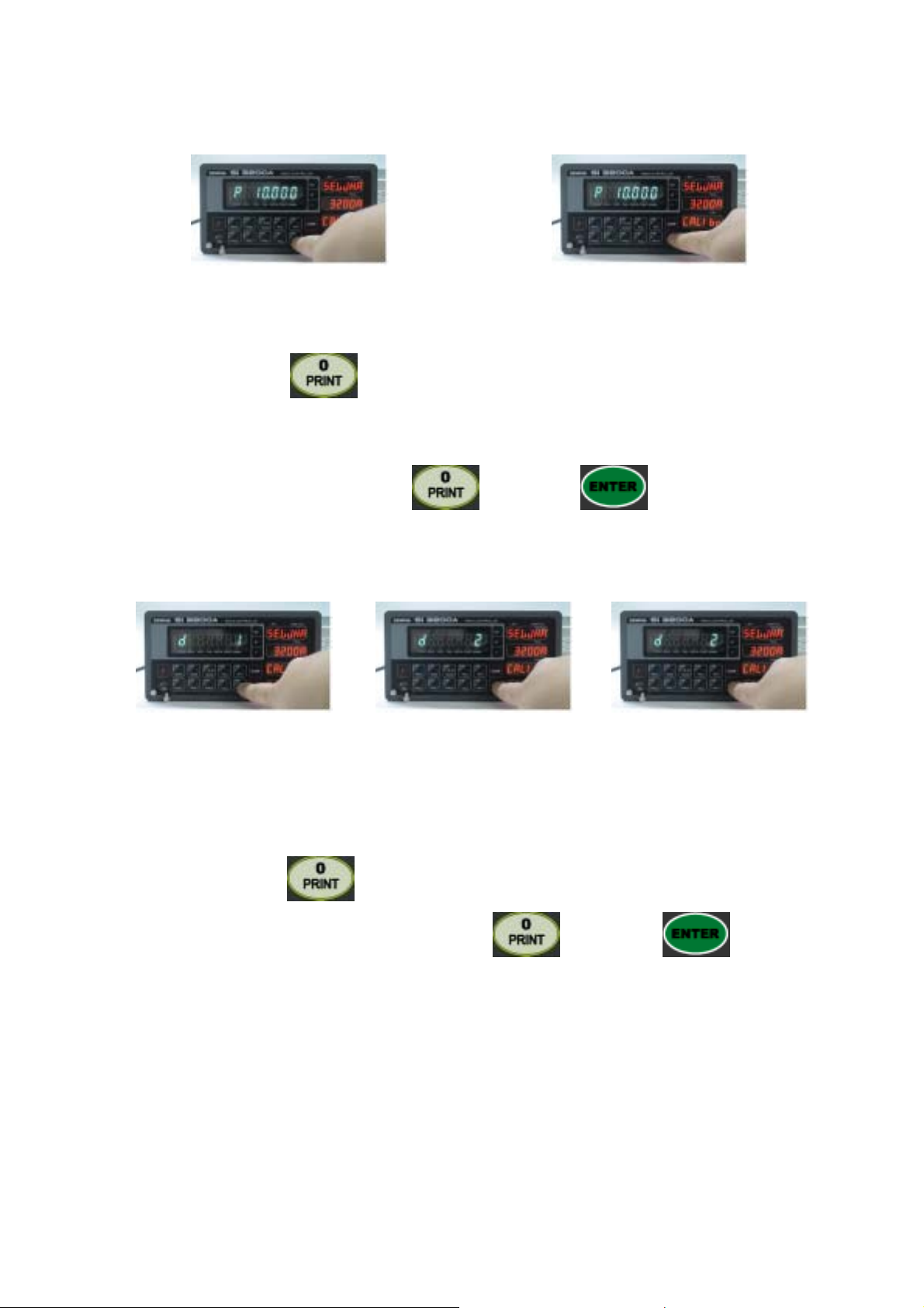
Decimal point position select with “0” key
Under this step, define the optimal position or Decimal point.
Whenever pressing
.XXX
The Max. Decimal point will be third place under Zero.
On the Optimal position, stop pressing
next step.
Step No.3 - Setting “Digit / Division” value.
Set Digit(Division) with “0”
key, Decimal point will be changed, like XXX. – XX.X – X.XX -
key and press key to save and move to
Press “Enter” and move the next
Press “Enter” and move the next step.
Press “Enter” and move the
key.
Press “Enter” and move the next step.
Under this step, define the optimal Digit/Division value of weighing measurement.
Whenever pressing
On the optimal Digit/Division value, stop pressing
and move to next step.
Caution※
(Max. capacity value / division value) can not be over 20,000.(as Indicator resolution is 1/200,00).
If the value is over 20,000, Error message “ Err 01 “ will be displayed and move back “CAPA” mode
again.
Step No.4 - Measure the “DEAD Weight of Weighing Scale.
key, the Digit/Division value will be changed, like 01-02-05-10-50.
step.
key and press key to save
next step.
- 19 -
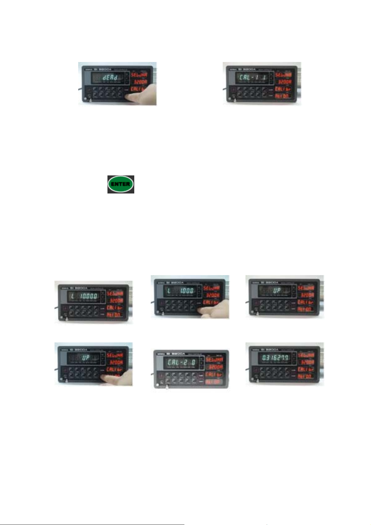
Memorize “DEAD weight” of Weighing Machine
Indicator will search “DEAD weight” during
with “Enter”.
Under this step, measure the “DEAD Weight of Weighing Scale”.
This “DEAD Weight” is very important to make “ZERO” value of weighing scale, so please make sure
that the weighing scale is empty and free from other external variations.
When you press
After finding optimal “Zero” value, automatically move to next step.
Caution※
At this step, if there some force or Vibration on Weighing scale, and unstable condition will be
continued, “ErrorA” will be display, and “DEAD value” will not be calculated.
Under this condition, please remove force or vibration and process it again.
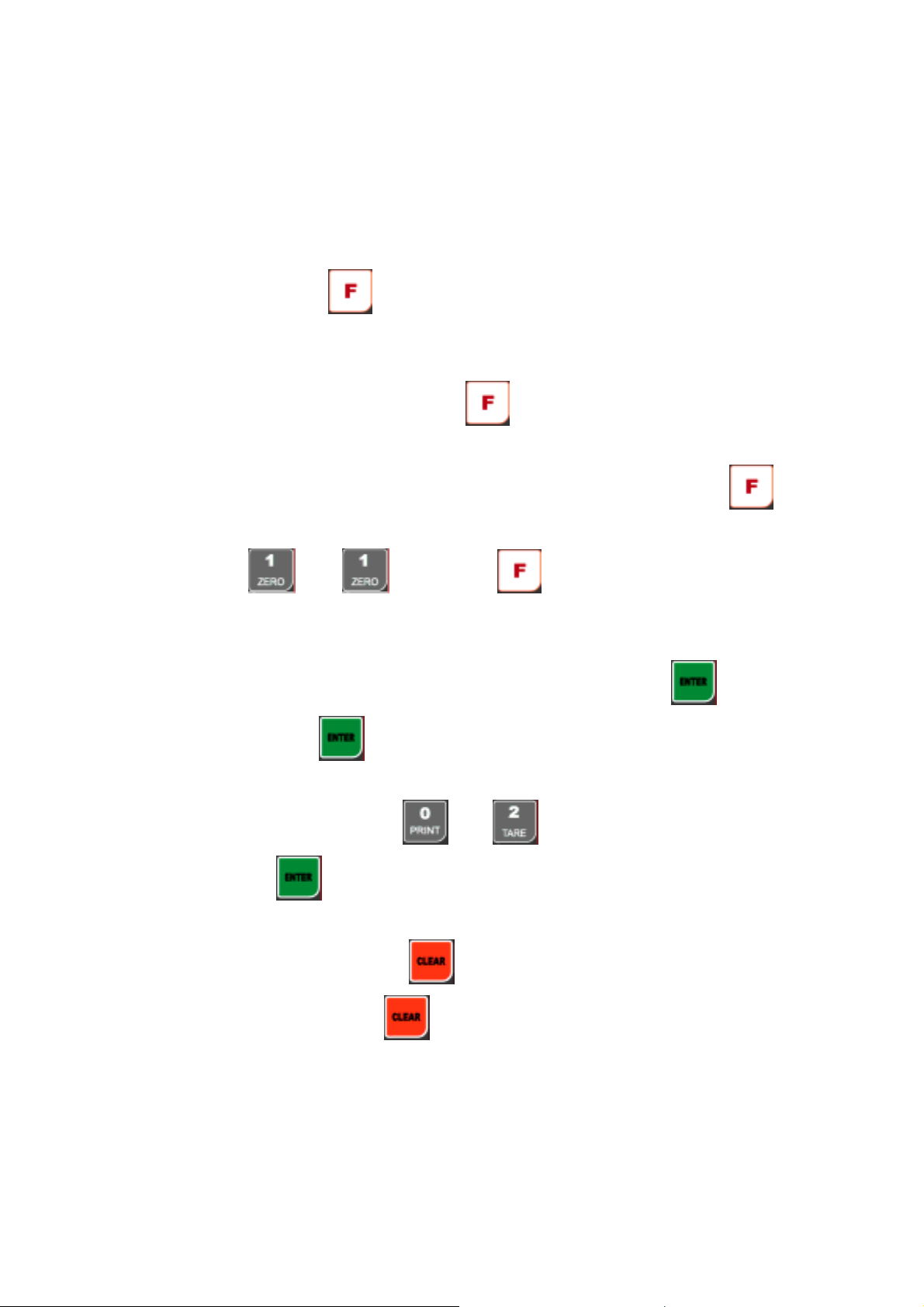
Step No.5 - Input Test Weight value and Calculate SPAN value.
key, the indicator starts to find “Zero” condition of scale during the 5sec.
5sec, automatically.
Input “Test weight” capacity
Process Span Calculation with
press “Enter”.
Under this step, input prepared “Test Weight’s value” and calculate “SPAN Value”.
The “Test Weight’s value” must be at least 10% max. capacity of weighing scale.
Input “Test weight” capacity and
press “Enter”.
Indicator will calculate span
value during 5sec, automatically.
Load “Test weight” on
After calculation, display span
weighing part.
value on the display
- 20 -
UP
Input prepared Test weight value and press
displayed.
Then load Test weight on weighing scale and press
Then, indicator will make adjustment for “Standard weight value” and calculate “Span value”.
※ “At least 10%” means to guarantee precise weighing process you have to make standard with at least
10% of weight of Max. capacity.
We programmed the calibration will not be done, when you load less than 10% of max. capacity.
Caution※
In case of Max. load cell capacity value /Division value is under 5,000, please prepare Standard
weight at least 10% of Max. load cell capacity value or max. display capacity value and set.
In case of Max. load cell capacity value / Division value is over 5,000, please prepare Standard weight
at least 20% of Max. load cell capacity value or Max. display capacity value and set.
This will be make more accuracy calibration setting.
- If you set test weight value over max. load cell capacity, Error Message “Err 04” will be displayed.
key, then message will be
key.
- If you set test weight value under 10% of max. load cell capacity value, Error Message “Err 05” will
be displayed.
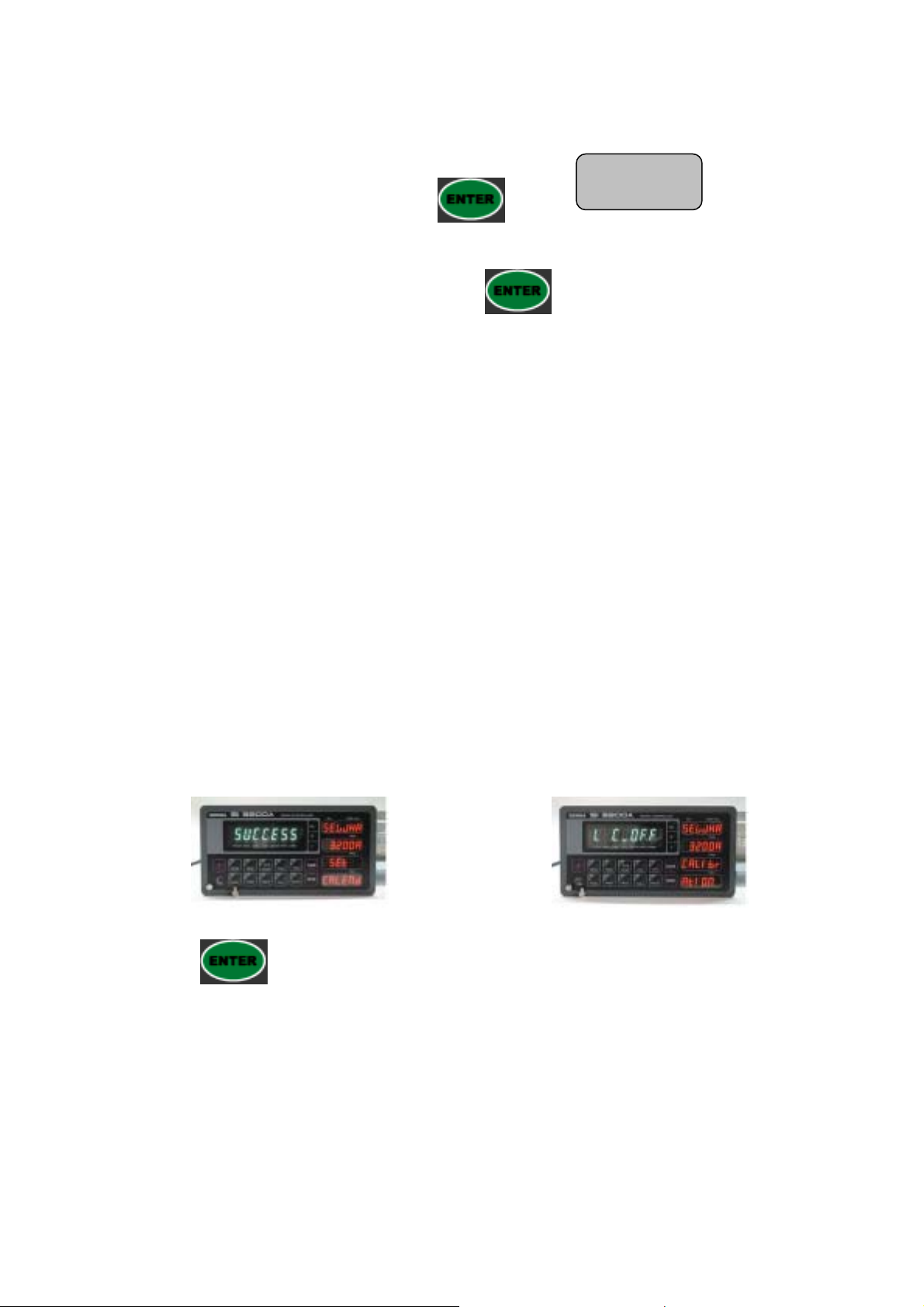
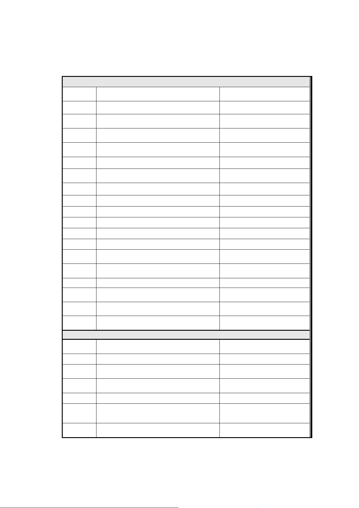
Step No.6 – End calibration process / “CAL” switch OFF
Now, the Test weight calibration is done.
Calibration process completed.
Press
Calibration Bolt.
Caution※
To process “Simulation Calibration” process, All indicator has its’ own standard value of 2mV gap.
So, if you replaced analogue board, you have to input standard value of 2mv gap.
And you can check the this 2mV gap value on F96. (value is between 200,00 ~400,000)
key to save all calibration process. Now, Off the “CAL LCK S/W” and fasten the
Push Calibration Lock S/W and tight Cal. Bol.
- 21 -
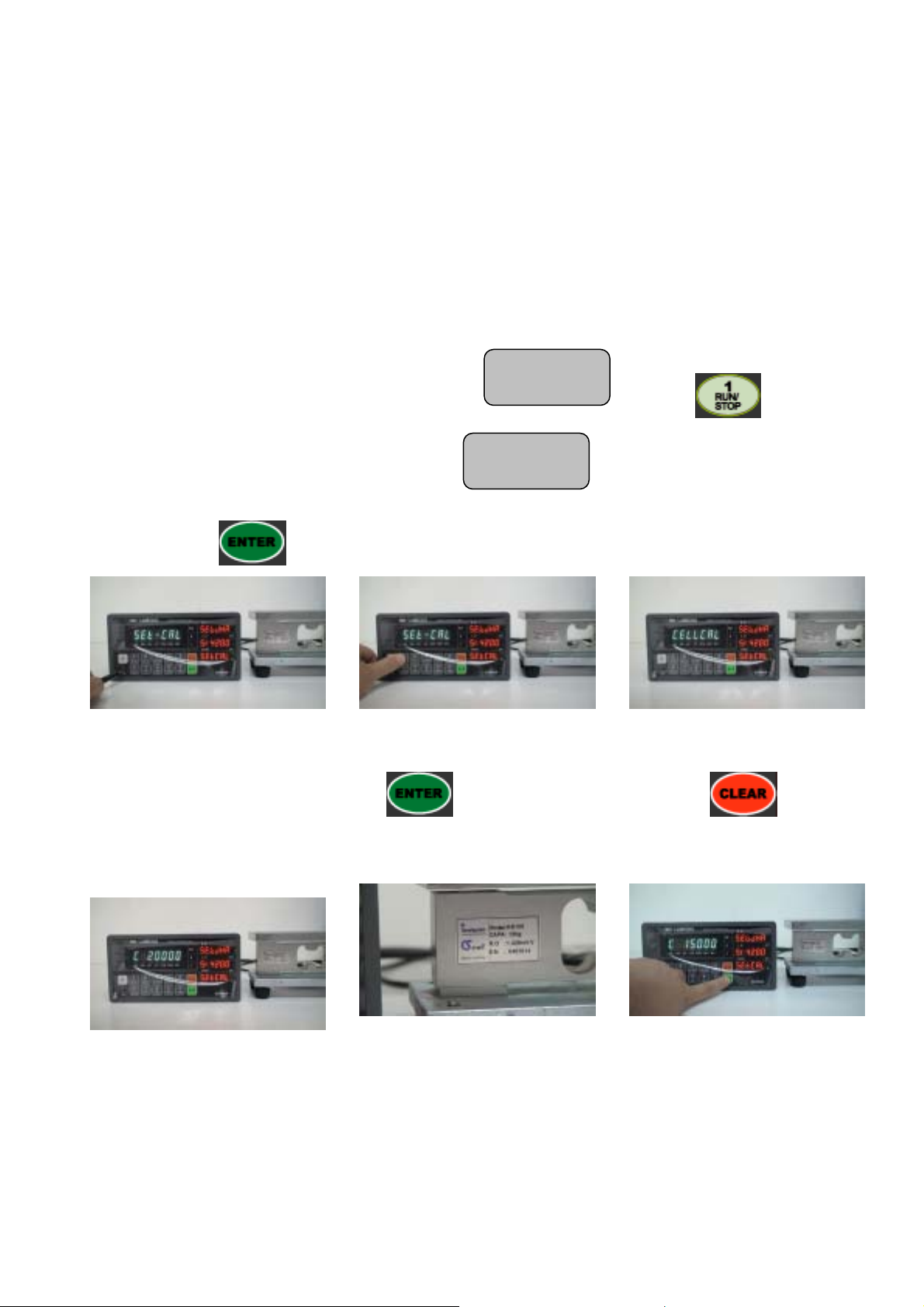
5-3. Simulation Calibration Mode (Calibrate without Test weight)
Through this “Simulation Calibration Mode” you can make simple calibration without Test weight.
This calibration mode uses “Load cells’ max. capacity” and “Max. Output Rate(mV)”, the weight
adjustment degree might be less than “Test weight Calibration”.
The guaranteed resolution of this “Simulation Calibration” is 1/3,000.
Remove “CAL-BOLT” on the Front panel and press “CAL - LOCK S/W” inside.
SeT-CAL
Then, you can enter the Calibration Mode with and press
CELCAL
enter “Simulation Calibration Mode” with and start calibration mode with
pressing
Remove the CAL.Bolt.
Push the CAL. S/W
※ For the save the each step, press
key.
Press NO.1 key to enter
the “CELL Calibration” mode
key, for the cancel or move back, press key.
Check the “CELL-CAL”. Massage
on display.
key to
Step No.1 - Setting “Capacity of Load cell”.
Enter the Capacity input mode
Under this step, input Max. Capacity of Load cell. (Not weighing Scale)
The Max. Capacity of load cell is stated on “Test report” or “Label”.
Check Max. Capacity of Load cell
(Refer the Load cell Lable)
- 22 -
Input the Max. Capacity of Load
cell(same value of Label
Please input this max. capacity of load cell value with No. keys.
After finishing input, press
Caution※
If the plural No. of load cells are installed, please make sum the all load cells capacity and input.
Ex) There are 4pcs of load cells are installed, and each load cell’s Max. capacity is 1,000kg.
Then, total Max. Capacity will be 4,000kg and you have to input 4,000kg.
Step No.2 - Setting “Decimal Point”
Enter the Decimal point input mode
Under this step, define the optimal position or Decimal point.
Whenever pressing
The Max. Decimal point will be third place under Zero.
key, Decimal point will be changed, like XXX. – XX.X – X.XX - .XXX
key and save and move to next step.
Input Decimal point and Press Enter to move next step
On the Optimal position, stop pressing
Step No.3 - Setting “Digit / Division” value.
Enter the division input mode
Under this step, define the optimal Digit/Division value of weighing measurement.
Whenever pressing
On the optimal Digit/Division value, stop pressing
key and press key to save and move to next step.
Select optimal division with pressing
“o” key
key, the Digit/Division value will be changed, like 01-02-05-10-50.
key and press key to save
Press Enter key and move to next
step.
- 23 -
and move to next step.
Caution※
(Max. capacity value / division value) can not be over 20,000.(as Indicator resolution is 1/200,00).
If the value is over 20,000, Error message “ Err 01 “ will be displayed and move back “CAPA” mode
again. But, under “Simulation Calibration Mode”, please make (Max. capacity value / division
value) setting is less than 3,000.
Step No.4 - Measure the “DEAD Weight of Weighing Scale.
Enter the “Dead weight” check mode
Under this step, measure the “DEAD Weight of Weighing Scale”.
This “DEAD Weight” is very important to make “ZERO” value of weighing scale, so please make sure
that the weighing scale is empty and free from other external variations.
When you press
of Scale” automatically.
Caution※
At this step, if there some force or Vibration on Weighing scale, and unstable condition will be
continued, “ErrorA” will be display, and “DEAD value” will not be calculated.
Under this condition, please remove force or vibration and process it again.
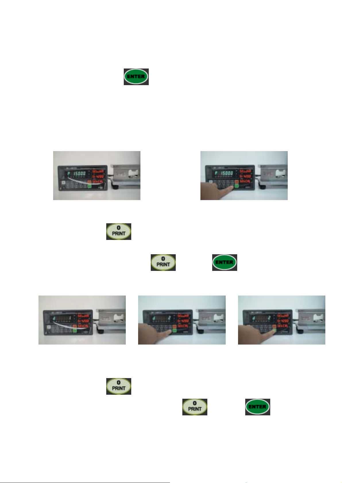
Step No.5 - Input Max. Output Rate(mV) of Load cell
key, the indicator start measurement and find optimal “Dead weight value
Indicator will seek optimal Dead Weight automatically.
Press Enter key.
Input Load cell Output Rate(mV)
(refer the load cell label)
Check Max. Rated Output value of
Load cell (Refer the Load cell Label)
- 24 -
After input Load cell’s Max. Rate
output value(mV) and press Enter
Under this step, input Max. Output rate(mV) of load cell.
The Output rate is stated on “Test report” or “Label” and please input this value with No. keys.
Normally, the Output rate will be 4digits under Zero, then input 4digits and input “0” additionally and
make full 6digits.
After input the value, press
After finishing calculation,
display.
Caution※
Due to some variation between “State output rate” and “Real Output rate” of load cell, there might
be some weight difference after finishing calibration.
If you want to make more precise weighing process, please measure real output rate of load cell and
input the measured value.
Then the weight measurement will be more precise than before.
Step No.6 – End calibration process and Calibration S/W OFF
key to make calculation.
Calculated “Span value” will be
Calibration process completed.
Now, the Simulation Calibration is done.
Press
Calibration Bolt.
key to save all calibration process and Off the “CAL LCK S/W” and fasten the
Push Calibration Lock S/W and tight Cal. Bol.
- 25 -
5-4. Set-up
Set-up means set the F-function and make SI 4410 weighing controller will perform more accuracy.
(Considering external / internal environmental condition)
5-4-1. Enter the Set-up Mode
1). Method : Press
press No.1 key and enter the “F-function” mode.
5-4-2. F-Function Change
Under F-function mode, Whenever press
one. Increase to F-90 and return to F-01
If you move to certain function No., press f-function no. with number key and press
Ex.) If you want to call “F11-XX ” directly under “F-function mode”.
Press “
Then, you can call “F22-XX” directly.
5-4-3. F-Function Set Value Change
Under F-Function mode, input New set value with Number keys and press
If you don’t press
” and “ ” key and press key.
key for 4sec. Then you can enter “F-Test” mode. Under this mode,
key, the Function No. will be increased one by
key, the new set value will not be memorized.
key.
key to save.
Ex.) If you want to change the “F01-01” to “F01-02”.
Under “F01-01” mode, press “ ” and “ ” key.
And press
5-3-4. Exit “F-function” Mode
Under “F-function” mode, press
Under “F-Test” mode, press
key to save.
key, you can move back to “F-Test” mode.
key once again, you can move back “Stand-by” mode.
- 26 -
5-5. F-Function List
General Function Setting
F01
F02
F03
F04
F05
F06
F07
F08
F09
F10
F11
F12
F13
F14
F15
F16
F17
Weighing Data Save Method selection
Weight-Back up selection
MOTION BAND Range setting
ZERO TRACKING Compensation
Range setting
Auto Zero Range setting
Digital Filter setting
“Zero/Tare” key Operation mode selection
“Zero” key operation range selection
“Tare” key operation range selection
Key TARE Operation Selection
External input selection
“Steady” condition check time setting
Display up-date rate setting
(FINAL, PRE1, PRE2, Free Fall ) set value
apply selection
SUB-Total / GRAND-Total Display selection
(When S/N key input)
Minus(-) display symbol use selection
“Near Zero” relay output mode selection
(Under “Zero” / “Gross Zero”)
0, 1, 2
0, 1
0 ~ 9
0 ~ 9
00 ~ 99
01 ~ 99
0, 1
0, 1, 2, 3
0, 1, 2, 3
0, 1
0, 1. 2, 3, 4
0 ~ 20
0 ~ 9
0, 1
0, 1
0, 1
0, 1
F18
F19
Equipment No. setting
Gross weight display selection
(Display on PRE2 display)
01 ~ 99
0, 1
Relay Output Mode Setting
F20
F21
F22
F23
F27
F28
F29
Auto Free Fall Compensation setting
Weighing Mode selection
FINISH relay delay time setting(t1)
(F21-01, 05, 06)
FINISH relay “ON” time setting(t2)
(F21-01, 05, 06)
Error relay(High/Low) “ON” time setting(t4)
Manual Discharge Selection
(F21-02, 04, 05, 06, 07)
PRE1 relay(Feeding) “ON” range selection
(F21-04, 05, 06, 07)
- 27 -
0~5
1, 2, 3, 4, 5, 6, 7
00~99
01~99
01~99
0, 1
0, 1, 2, 3, 4, 5, 6, 7, 8, 9
 Loading...