

Sewha SI 4200 Instruction Manual
Digital Weighing Controller
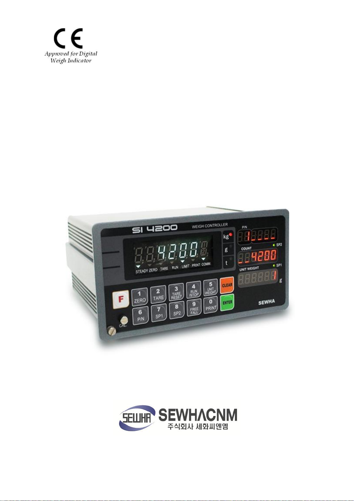
SI 4200
Instruction Manual
Ver. 3.15 May 2011

Digital Weighing Indicator
- 2 -
1. Before Installation
---------------
3 page
2. Introduction
---------------
4 page
3. Specification
---------------
5 page
4. Installation
4-1. External Dimension & Cutting Size
4-2. Load Cell Installation
4-3. Installation Components
---------------
---------------
---------------
---------------
11 page
11 page
11 page
12 page
5. Set-up
5-1. Calibration
5-2. TEST Weight Calibration Mode
5-3. Simulation Calibration Mode(Without Test Weight)
5-4 Unit Calibration Mode
5-5. F-Function Setting
5-6. F-Function List
---------------
---------------
---------------
---------------
---------------
---------------
---------------
14 page
14 page
14 page
17 page
20 page
22 page
23 page
6. Interface
6-1. Serial Interface (RS-232C)
6-2. Current Loop Interface
6-3. Print Interface (Option 01 : Centronics Parallel Interface)
6-4. Analog Output Interface (Option 02 : 0~10V)
6-5. Analog Output Interface (Option 03 : 4~20mA)
6-6. Serial Interface (Option 04 : RS-232C / 422 / 485)
6-7. BCD INPUT (Option 05)
6-8. BCD OUTPUT (Option 06)
6-9. Command Mode
---------------
---------------
---------------
---------------
---------------
---------------
---------------
---------------
---------------
---------------
35 page
35 page
39 page
40 page
42 page
43 page
44 page
45 page
46 page
47 page
7. Error & Treatment
7-1. Load Cell Installation
7-2. Calibration Process
7-3. Indicator Error & Treatment
7-4. Indicator Test Mode
---------------
---------------
---------------
---------------
---------------
49 page
49 page
49 page
50 page
51 page
Warrantee Certification
---------------
52 page
SI 4200
CONTENTS

- 3 -
This mark warns the possibility to arrive death or serious injury in
case of wrongly used.
This mark cautions the possibility to arrive serious human body
injury or product lose in case of wrongly used.
Warning for Electric Shock or Damage.
Please do not touch by hand
Protective Ground(Earth) terminal
Prohibition of Operation process
Warning
Caution
1. BEFORE INSTALLATION
1-1. Caution / Warning Marks
1-2. Other Marks
Digital Weighing Indicator
SI 4200
1-3. Copy Rights
1).All Right and Authority for this Manual is belonged to Sewhacnm Co.,Ltd.
2).Any kinds of copy or distribution without Sewhacnm Co.,Ltd’s permission will be prohibited.
1-4. Inquiries
If you have any kinds of inquiries for this model, please contact with your local agent or Head Office.
Head Office : Sewhacnm Co.,Ltd.
Website : http://www.sewhacnm.co.kr
Email : info@sewhacnm.co.kr , sales@sewhacnm.co.kr

Digital Weighing Indicator
- 4 -
2. INTRODUCTION
2-1. Introduction
Thank you for purchasing, this “SI 4200” Industrial Digital Weighing Controller.
This “SI 4200” model is advanced model for “Quantity Control application”, with 2ports serial port
interfaces and precise weighing control system, you can upgrade your weighing process.
This “SI 4200” Weighing Controller is suitable for any kinds of Weight Capacity with Counting by “Unit
Weight Calibration”.
Enjoy your process with “SI 4200” Weighing Controller.
2-2. Cautions
1) Don’t drop on the ground or avoid serious external damage on item.
2) Don’t install under sunshine or heavy vibrated condition.
SI 4200
3) Don’t install place where high voltage or heavy electric noise condition.
4) When you connect with other devices, please turn off the power of item.
5) Avoid from water damage.
6) For the improvement of function or performance, we can change item specification without prior notice
or permission.
7) Item’s performance will be up-dated continuously base on previous version’s performance.
2-3. Features
1) All Modules and Option Cards are isolated to maximize accuracy and performance.
2) External input terminal inside.(4pcs:Can be set by F11 mode)
3) By using “Photo-Coupler” on each module(Option, Analog board, In/Out), we improved “Impedance
problem”, “Isolation ability among inputs”, “Leading power problem”, and “Noise covering function”.
4) Data back-up function, when the sudden power off.
5) “Set value Error” check function added. – Check “Set values for each weighing mode”.
- If there is any wrong set value, “E” will be display and will not start weighing process
6) Polycarbonate film panel, strong for dust and water.
7) Weight Unit selection Function added. (“g”, “kg”, “t” selectable – F40)
8) Variable options(Order in advance, Refer Chapter 6. Interface) – “RS-232C” Standard installed.
9)2port Serial Interface available – various applications are available.
10) Simulation Calibrate mode added (Can calibrate without Test weight)
- 5 -
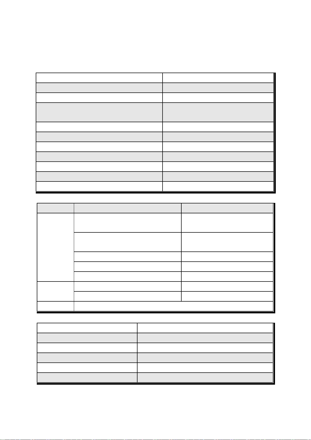
Input Sensitivity
0.2㎶ / Digit
Load Cell Excitation
DC 10V ( - 5V ~ + 5V )
Max. Input Signal
Max.3.2mV/V
Temperature Coefficient
[Zero] ±16PPM/℃
[Span] ±3.5PPM/℃
Input Noise
±0.3㎶ P.P
Input Impedance
Over 10㏁
A/D Conversion Method
Sigma-Delta
A/D Resolution(Internal)
520,000 Count(19bit)
A/D Sampling Rate
Max. 500times / Sec
Non-Linearity
0.005% FS
Display Resolution(External)
1/20,000
Display
Parts
Specification
Display
Main Display
7Segments, 7digits VFD green Color
Size :12.7(H) ×7.0(W)mm
Sub-Display
7Segments, 6digits FND, Red Color
Size : 9.2(H) ×4.8(W)mm × 3lines
Min. Division
×1, ×2, ×5, ×10, ×20, ×50
Max. display value
+999,950
Under Zero value
"-" (Minus display)
Status lamp
Steady, Zero, Tare, RUN, LIMIT, Print, Comm.
" ▼" Condition display Lamp
kg, g, t / SP1, SP2
Red / Yellow-Green LED Display(3Ø )
K e y
Number Key, Function, CAL. Lock key (14pcs)
Power Supply
AC110/220V(±10%), 50/60Hz, about 30VA
Operating Temperature Range
-10℃ ~ 40℃
Operating Humidity Range
Under 85% Rh (non-condensing)
External Dimension
200mm(W)x105mm(H)x165mm(L)
Net Weight(kg)
About 2.3kg
Gross Weight(kg)
About 3.0kg
3. SPECIFICATION
3-1. Analog Input & A/D Conversion
Digital Weighing Indicator
SI 4200
3-2. Digital Part
3-3. General Specification
※ AC 110V, Power supply is an optional before ex-factory.
- 6 -
Option No.1
Printer Interface : Centronics Parallel
Option No.2
Analog Output (0~10V or 0~5V)
Option No.3
Analog Output (4~20mA)
Option No.4
Serial Interface : RS-232C / 422 / 485
Option No.5
BCD INPUT (P/N change purpose)
Option No.6
BCD Output
Option No.7
Ethernet
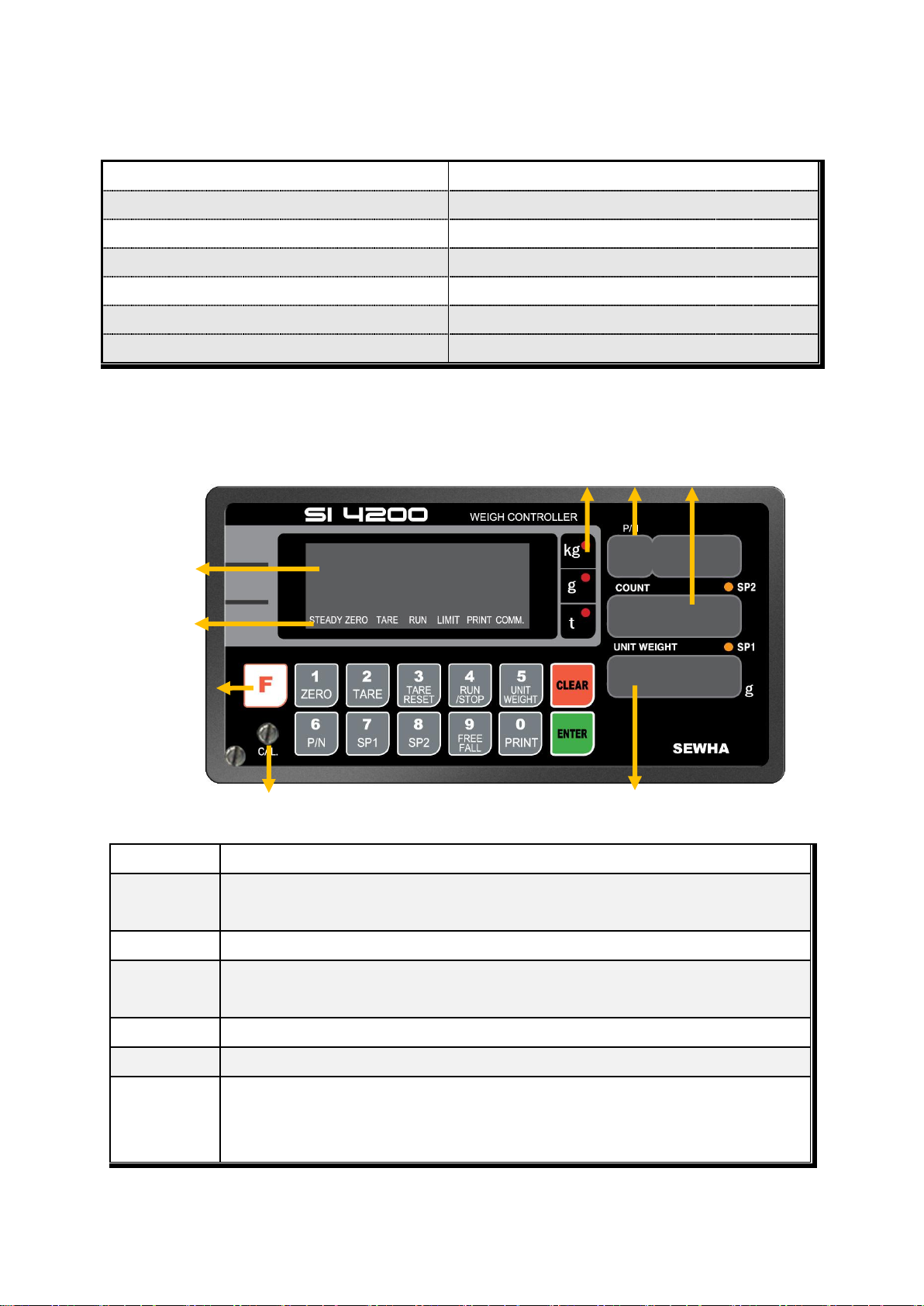
Steady
When the weight is Steady, “▼” Lamp is turn on.
Zero
When the current weight is Zero, “▼” Lamp is turn on.
(Displayed weight is Zero, “▼” Lamp is turn on.)
Tare
Tare function is set, “▼” Lamp is turn on. (Tare Reset “▼” Lamp is turn off.)
RUN
Under Packer Mode(F21-02) setting.
Start Packer Mode “▼” Lamp is ON
LIMIT
Under Limit Mode(F21-01) setting. “▼” Lamp is ON.
Print
When print key input or Auto print, “▼” Lamp is turn on.
Comm.
When indicator transfers or receives data from other devices, “▼” Lamp is turn on.
(If the “▼” is off although there is some data transference, please check communication
settings).
Weight Display
Status Lamp
Function Key
Unit Weight
Count
Weight Unit
P/N
Calibration Lock-Key
3-4. Option Card
※ Serial Interface (RS-232C) or Current Loop is Standard installed.
In the Optional Serial port, there is no Current Loop function
3-5. Front Panel (Display / Key Pad)
Digital Weighing Indicator
SI 4200
3-5-1. Status Lamp (ANNUNCIATORS) : “▼” Lamp is “ON”.
- 7 -
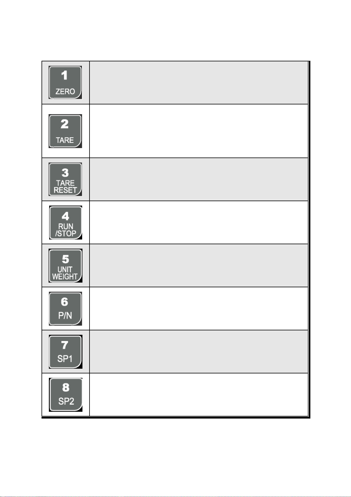
Make Weight value as Zero.
Under F08, you can set the Zero key operation range, as 2%, or 5%, or 10%, or 20% of
Max. Capacity.
※ Under “Tare” key input, Zero key will not be activated.
Make Weight value as Zero, including Tare Weight.
Under F09, you can set the Tare key operation range, as 10%, 20%, 50%, or 100% of
Max. Capacity.
Tare setting : Under F10-00 setting, “TARE” key input
Under F10-01 setting, “Tare”+ No. key + “Enter”
Remove set TARE value.
Under Packer Mode(F21-02), Start the packer mode process.
First input is “START”, Second input is “STOP”
Manual “Unit Weight” input Key.
If you already knew the “Unit Weight”, you can input “Unit weight” without calibration.
You can set each weighing process as a certain P/N.
Each weighing process will be saved with FINAL, PRE1, PRE2, and Free Fall set
value.(Max. 50 kinds of P/N you can set)
And you can call certain P/N with each set value.
You can set SP1 value through this key.
You can set SP2 value through this key.
3-5-2. Key Operation
Digital Weighing Indicator
SI 4200
Digital Weighing Indicator
- 8 -
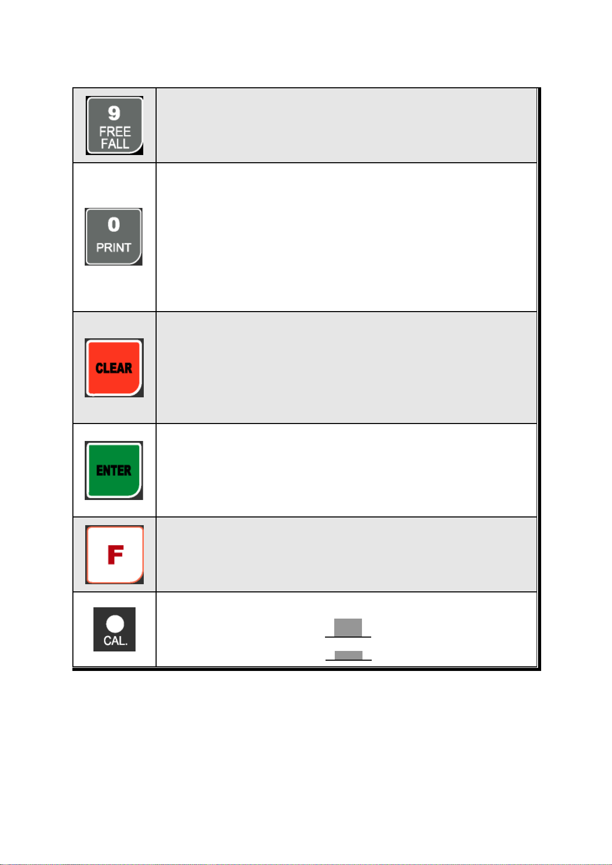
You can set FREE FALL value through this key.
1. Manual Print (F38-00 setting, under F35-01)
2. Manual weighing Data save for accumulated weighing count and weight.
(F01-00 / 02 setting)
3. Calibration mode
- Digit setting
Whenever pressing “0”key, digit will be change 1, 2, 5, 10, and 50.
- Decimal point position
Whenever pressing “0”key, decimal point will be change.
1. Modify the set value during setting process.
2. Calibration mode
- Move back to previous step.
F-function Mode.
- F-function Exit : Press “Clear” key, once.
- F-Test Mode Exit : Press “Clear” key, twice.
1. Save set value during setting process.
2. Calibration mode
- Save current setting and move to next step.
3. F-Function mode
- Save current F-function setting, and move to next F-function
1. “F-TEST” Mode Entrance : Press “F” key for 5sec.
2. Under “F-function Mode”, Move to next Function or move to certain function
No.(Press function No. and press “F” key)
3. Function key (Refer “Function keys”)
Enter/Exit to “Calibration” mode.
“ON” : Enter to Calibration Mode.
“OFF” : Exit from Calibration Mode.
SI 4200
- 9 -
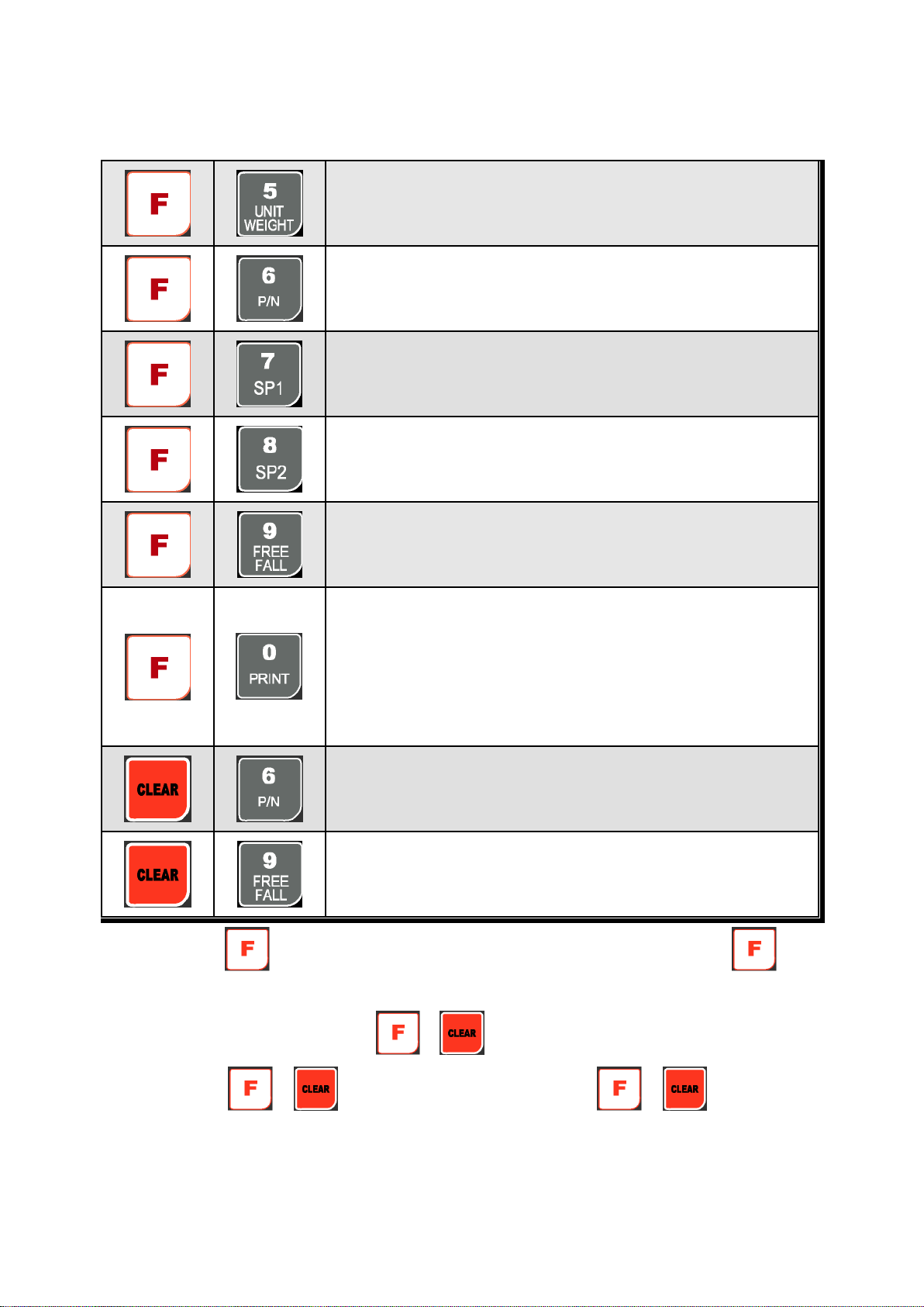
Enter “Unit Weight Calibration” mode.
- Please refer “5-4. Unit Calibration”.
Print all P/Ns’ accumulated weighing count and weight.
(Grand-Total Print)
High Range value setting (N.G Relay).
Under Range value setting(N.G Relay)
Print current P/N’s accumulated weighing count and weight.
(Sub-Total Print)
Display accumulated weighing count and weight
Max. accumulated weight display : 21,474,839,647(g, kg, ton)
Max. accumulated weighing count : 999,999times
※ Under F15, you can set what kinds of accumulated count and weight.
- F15-00 : Display current P/N’s accumulated count and weight.
- F15-01 : Display all P/Ns’ accumulated count and weight
Delete all P/Ns’ accumulated weighing count and weight
(If you set F44-01, the data will be automatically deleted after “Grand-Total
Print).
Delete current P/N’s accumulated weighing count and weight
(If you set F44-01, the data will be automatically deleted after “Sub-Total
Print).
※ “Function Keys”(Combined Key Function)
Digital Weighing Indicator
SI 4200
※ After Pressing key, you have to input above function keys within 5sec. - After 5sec, the key
activation is loose
※ If you set “F51-01” you can check the / key activation through Main display.
※ After Pressing “ ”, “ ” key, non-function keys are input, the “ ”, “ ” key
activation will be loose.
- 10 -
Warning
③ OPTION CARD
②
○3
○6
○5
○4
○7
○
1
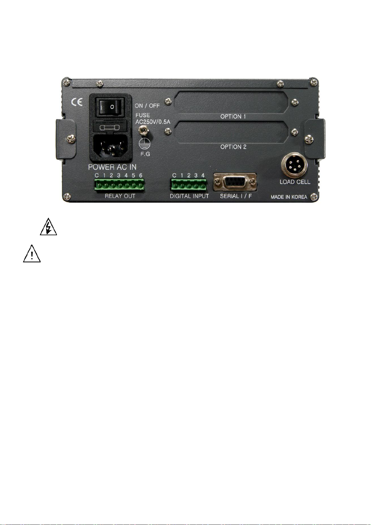
3-6. Rear Panel
Digital Weighing Indicator
SI 4200
○1 POWER AC IN
- Power switch : Power on/off switch.
- Fuse : AC250V / 0.5A , φ5.25 , 20mm.
- AC IN : Available Input AC 110V / 220V.
※ The standard power supply is AC 220V(Fixed when ex-warehouse), if you want to have AC 110V,
please inform in advance.
② Option Card 1
③ Option Card 2
※Option Card Connector installed for Optional Interface or Output.
(Printer I/F, Analog out, RS-422/485, or RS-232C(two port)
④ LOAD CELL Connector (N16-05)
⑤ SERIAL I/F
“RS-232C” or “CURRENT LOOP”(9Pin, D-Type Female) are built-in as standard
⑥ External Input : External control input for wired remote control.
Refer to F-Function F11 to select desired function mode.
Input signal …………………………… Optical-Isolator
⑦ Relay Output Terminal : Set point(SP1, SP2, SP3, SP4) and Finish, Empty relay output.
(Refer “F21” setting.)
- 11 -
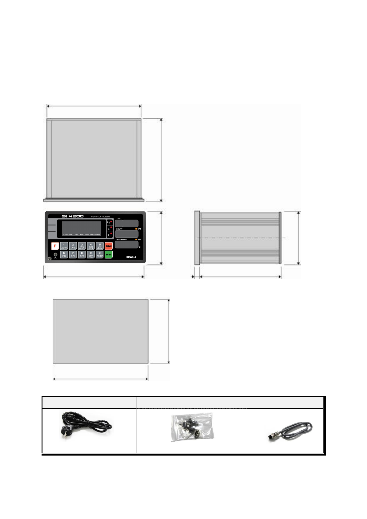
Power Cable
Communication Connector(D-SUB 9P)
Load-cell Cable
94
188
165
105
200
162.0
92
186
4. INSTALLATION
4-1. External Dimension & Cutting Size
(External Dimension) (unit : mm)
Digital Weighing Indicator
SI 4200
(Cutting Size) (unit : mm)
4-2. Installation Components
- 12 -
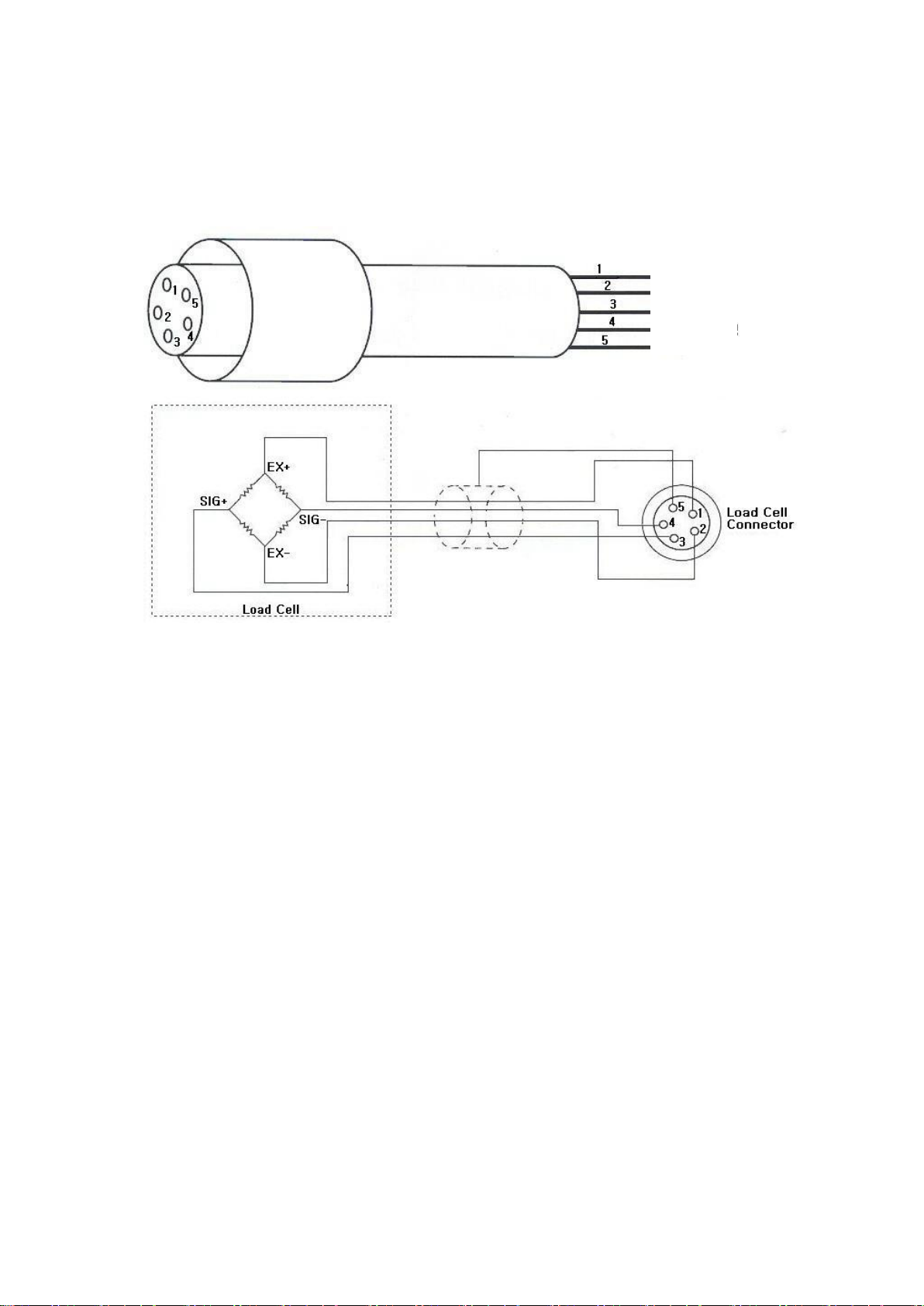
Red
White
Green
Blue
Shield
4-3. Load Cell Connector Specification
4-3-1. Load Cell Connector Specification
Digital Weighing Indicator
SI 4200
4-3-2. Load Cell Installation
1) You can connect Max. 8pcs of same capacity Load cells at once. (350Ω)
2) You have to make horizontal balance on the ground.
3) If you install more than 2pcs of Load cells, use Summing box and adjust output signal difference as
minimum. It can make wrong weighing process caused by each load cell’s variation.
4) If there is some temperature difference around Load cell, it can cause wrong weight measurement.
5) Don’t do Welding job or Arc discharge around installation place. But, there is no choice, please
disconnect power cable and Load cell cable.
6) If you measure static electricity material, please make earth between down part and up part of Load
cell.
- 13 -
Single Load cell use
0.2㎶ ≤
EⅹBⅹD
A : Load cell capacity(kg)
B : Load cell Voltage(mV)
D : Digit
E : affirmation Voltage of Load cell
N : Number of Load cell
A
Plural Load cells use
0.2㎶ ≤
EⅹBⅹD
AⅹN
5000ⅹ2ⅹ0.05
= 1 ≥ 0.2㎶
The calculated value is larger than 0.2㎶,
so this system has no problem.
500
5000ⅹ2ⅹ0.10
= 0.5 ≥ 0.2㎶
The calculated value is larger than 0.2㎶,
so this system has no problem.
500ⅹ4
Caution
!
4-2-4. Formula to plan the precise weighing system
This “SI 4200” weighing controller’s Max. input sensitivity is 0.1㎶ / Digit.
And for precise weighing system, the following formula must be satisfied.
Caution : “Input sensitivity” means Min. output voltage variation of weighing part to change 1digit. So,
please do not make large input voltage to make reliable weighing system.
Example1.)
The number of Load cell : 1pcs
Load cell capacity : 500kg
Digital Weighing Indicator
SI 4200
Load cell Rated output : 2mV/V
Division : 0.05kg
Affirmation Voltage of Load cell : 5,000mV
Max. Capacity of Weighing System : 300kg
Then, estimation result for this weighing system with formula,
Example2.)
The number of Load cell : 4pcs
Load cell capacity : 500kg
Load cell Rated output : 2mV/V
Division : 0.10kg
Affirmation Voltage of Load cell : 5,000mV
Max. Capacity of Weighing System : 1,000kg
Then, estimation result for this weighing system with formula,
※ According to “Resolution” or “Capacity”, it might not be calibrated like calculation.
Digital Weighing Indicator
- 14 -
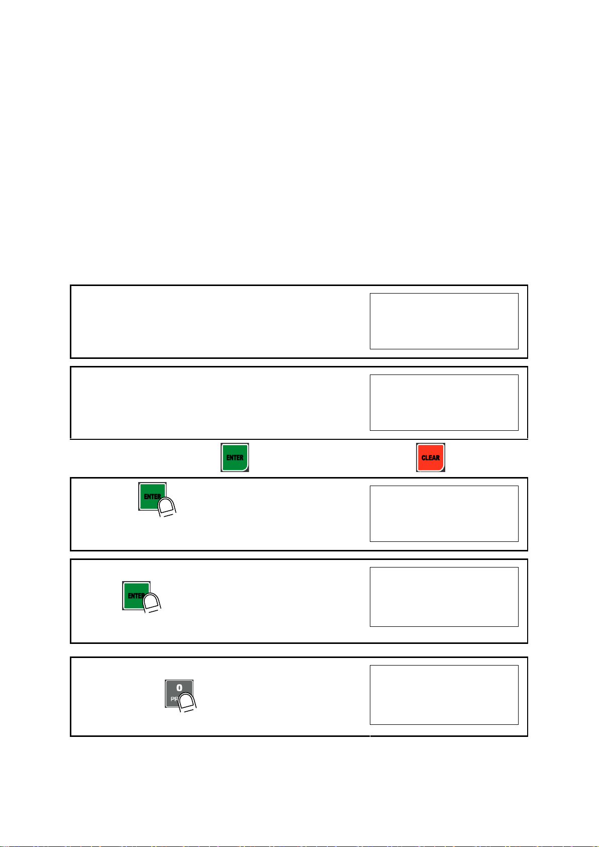
1. At normal mode, remove “CAL-BOLT” on the Front panel
123
2. And press “CAL - LOCK S/W” inside.
Check the “SET-CAL. Massage on display.
5et-Cal
※ For the save the each step, press key, for the cancel or move back, press key.
3. If you press key, Calibration Mode starts.
After displaying “CAPA”,
C999999
4. Please input Max capacity of your weighing scale,
And press key.
Ex) Load cell CAPA : 20kg, division : 0.001 Input 20000
C 20000
5. define the optimal position or Decimal point
Whenever pressing key, Decimal point will be changed.
Ex) Load Cell CAPA : 20kg, division : 0.001kg input 20.000
p 20.000
5. SET-UP
5-1. Calibration
Adjust weight balance between “Real weight” on the load cell(Weight Part) and “Displayed weight of
Indicator”. When you replace LOAD CELL or Indicator, you have to do Calibration process once again
5-2. Test Weight Calibration Mode (Using Test weight)
※remarks : In case that “P-W” is displayed, you have to check the pass word.
Prepare At least 10% of Max. capacity of your weighing scale, and remove “CAL-BOLT” on the Front
panel and press “CAL - LOCK S/W” inside.
※remarks : In case that “P-W” is displayed, you have input the pass word to start
calibration mode.
SI 4200
Digital Weighing Indicator
- 15 -
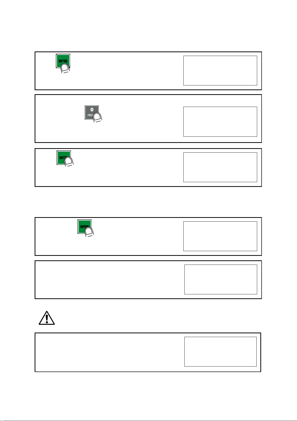
6. Press key to save and move to next step.
p 20.000
7. Define the optimal Digit/Division value of weighing measurement.
Whenever pressing key, the Digit/Division value will
be changed like 1->2->5->10->20->50.
Ex) Load cell CAPA : 20kg, division : 0.001 Input division “1”
d 1
8. press key to save the Digit/Division value and move
to next step
d 1
※ Caution : (Max. capacity value / division value) cannot be over 20,000.(as Indicator resolution is 1/20,000).
If the value is over 20,000, Error message “ Err 01 “ will be displayed and move back “CAPA” mode again.
9. When you press key, the indicator starts to find
“Zero” span..
dead
10. Indicator will search “DEAD weight” during 5sec, automatically.
After finding optimal “Zero” span , step is automatically
Moves to next.
Cal-1 0
※ Caution : At this step, if there some force or Vibration on Weighing scale, and unstable condition will be
continued, “ErrorA” will be display, and “DEAD value” will not be calculated.
Under this condition, please remove force or vibration and process it again.
11. Span Calibration mode starts..
l 20.000
SI 4200
Digital Weighing Indicator
- 16 -
12. Input “Test weight” capacity. And press key.
Ex) Load Cell CAPA : 20kg, division 0.001
Use test weight(at least 2kg) which is 10% of max CAPA(20kg)
input test weight 2.000
l 2.000
13. After displaying “UP” ,please load “Test Weight” .
Ex) Load Cell CAPA : 20kg, division 0.001
Use test weight(at least 2kg) which is 10% of max CAPA(20kg)
Up
14. And press key.(Do not unload test weight)
Up
15. Indicator will calculate span value during 5sec, automatically
Cal-2 0
16. After calculation, span value displays on the display.
Please unload the test weight.
0.629238
※ Caution : The “Test Weight’s value” must be at least 10% max. capacity of weighing scale.
“at least 10%” means to guarantee precise weighing process you have to make standard with at least
10% of weight of Max. capacity.
We programmed the calibration will not be done, when you load less than 10% of max. capacity.
17. Press key to save all calibration process.
After then it resets automatically.
(Now, fasten the Calibration Bolt. )
end
SI 4200
 Loading...