

Sewha SI 410 User Manual

Digital Weighing Indicator
SI 410
User Manual
Ver 2.0 2017.04.05

- 2 -
Contents
1. BEFORE INSTALLATION .................................................................................................................... - 3 -
2. INTRODUCTION ................................................................................................................................. - 4 -
2-1. Introduction .......................................................................................................................................................... - 4 -
2-2. Cautions ................................................................................................................................................................. - 4 -
2-3. Features .................................................................................................................................................................. - 4 -
3. SPECIFICATION ................................................................................................................................... - 5 -
3-1. Specification ......................................................................................................................................................... - 5 -
3-2. Option ..................................................................................................................................................................... - 6 -
3-3. Front Panel ........................................................................................................................................................... - 6 -
4. Installation ........................................................................................................................................ - 11 -
4-1. External Dimension & Cutting Size .........................................................................................................- 11 -
4-2. Installation Components ..............................................................................................................................- 11 -
4-3. Load cell Installation ......................................................................................................................................- 12 -
5. Set-Up ................................................................................................................................................ - 13 -
5-1. Set-up mode ......................................................................................................................................................- 13 -
5-2. Test Weight Calibration Mode (Using test weight) .........................................................................- 15 -
5-3. Simulation Calibration Mode (Calibrate without Test weight) ...................................................- 20 -
5-4. F-FUNCTION Setting ......................................................................................................................................- 24 -
5-5. Set Point value input .....................................................................................................................................- 42 -
5-6. Test Mode ...........................................................................................................................................................- 43 -
6. INTERFACE ........................................................................................................................................ - 48 -
6-1. Serial Interface ..................................................................................................................................................- 48 -
6-2. External input ....................................................................................................................................................- 63 -
6-3. Relay output ......................................................................................................................................................- 63 -
6-4. Current loop .......................................................................................................................................................- 64 -
6-5. Analogue I-Output Interface : 4~20mA ................................................................................................- 65 -
6-6 Analog V-Output Interface : 0~10V ........................................................................................................- 66 -
6-7. Analog output selection ...............................................................................................................................- 67 -
6-8. Print Interface ....................................................................................................................................................- 67 -
6-9. BIN IN card (Changing Product number) ............................................................................................- 68 -
6-10. BCD OUT Card (Weight data out) ........................................................................................................- 69 -
6-11. Ethernet card ...................................................................................................................................................- 70 -
6-12. SD Option Card .............................................................................................................................................- 70 -
6-13. Option card combination ..........................................................................................................................- 71 -
7. Error & Treatment ........................................................................................................................... - 72 -
7-1. Load Cell Installation .....................................................................................................................................- 72 -
7-2. Calibration Process .........................................................................................................................................- 73 -
7-3. Digital Weighing Indicator ..........................................................................................................................- 74 -
- 3 -
1. BEFORE INSTALLATION
Caution / Warning Marks
This mark warns the possibility to arrive death or serious injury
in case of wrongly used.
This mark cautions the possibility to arrive serious human body
injury or product lose in case of wrongly used.
Copy Rights
1. All Right and Authority for this Manual is belonged to SEWHA CNM CO., LTD.
2. Any kinds of copy or distribution without permission of SEWHA CNM CO., LTD. will be
prohibited.
3. This manual may be changed as the version is upgraded, without previous notice.
Inquiries
If you have any kinds of inquiries for this model, please contact your local agent or Head Office.
1. Head Office : SEWHACNM CO., LTD.
2. Website : http://www.sewhacnm.co.kr
3. Email : sales@sewhacnm.co.kr
4. TEL : +82-32-624-0060

- 4 -
2. INTRODUCTION
2-1. Introduction
Thank you for your choice of this SI 410 Industrial Digital Weighing Indicator.
This SI 410 model is high-performance weighing Indicator.
Please review and learn this instruction Manual and enjoy your process efficiency
with “SI 410” Weighing Indicator.
2-2. Cautions
1. Don’t drop on the ground and avoid serious external damage on item.
2. Don’t install under sunshine or heavy vibrated condition.
3. Don’t install place where high voltage or heavy electric noise condition.
4. When you connect with other devices, please turn off the power of item.
5. Avoid from water damage.
6. For the improvement of function or performance, we can change item specification without
previous notice or permission.
7. Item’s performance will be up-dated continuously base on previous version’s performance.
2-3. Features
1. SI 410 model is standard size indicator which is easy to install on the panel.
2. Front panel is covered with Polycarbonate film, strong against dust and water.
3. RS232 Serial interface is standard installed.
4. User can choose various options; Analog output 4~20mA, 0~10V / RS232C / RS422,
RS485 / ETHERNET CARD / BCD OUT / BIN IN / SD Memory card

- 5 -
3. SPECIFICATION
3-1. Specification
Content
Specification
Analog Part
Display Resolution
1/20,000
Internal Resolution
1/2,000,000 (±1,000,000)
Input Sensitivity
Min 0.1µV/V
Max Signal Input Voltage
Max 3.0mV/V
Load cell Excitation
DC +5V
A/D Conversion Method
Sigma-Delta
Decimal Point
0, 0.0, 0.00, 0.000
Drift
Offset
10PPM/℃
Span
10PPM/℃
Non Linearity
0.001% of Full Scale
Analogue Sampling(sec)
60times / sec(MAX)
Environment
Operating Temperature
Range
-10℃ ~ +40℃ [14℉ ~ 104℉]
Operation Humidity Range
40% ~ 85% RH, Non-condensing
Function
Calibration Mode
Test Weight Calibration Mode
Simulation Calibration Mode
Display
6 digit, 25.4mm(1inch) Red FND for Numbers
7 digit, Red LED for Weight unit
8 digit, Green LED for State alarm
12 digit Greed LED for Arrow
Key Pad
14pcs Standard Key pad
Additional Digital Input
6pcs external input key
Communi-
cation
Serial Port 1
(RS-232)
Data Transference
Command Mode
Serial Printer Mode
Modbus (RTU)
Relay Output
Relay Output
7pcs selectable relay output
Power
AC : 110~240V, Maximum Power Consumption 19W
Size
200mm(W)ⅹ100mm(H)ⅹ126.5mm(D)
Weight : 1250g

- 6 -
3-2. Option
Option1
Serial Port (RS-422)
Option2
Serial Port (RS-485)
Option 3
Serial Port (RS-232)
Option 4
ETHERNET CARD
Option 5
Analog Output(0~20mA)
Option 6
Analog Output(0~10V)
Option 7
BCD OUT
Option 8
BIN IN
Option 9
SD Memory card
3-3. Front Panel
3-3-1. Front Panel (Display / Key Pad)
- 7 -
3-3-2. State LED
LED
State
STEADY
When the weight is stable, ON.
ZERO
When the current weight is near zero, ON.
TARE
When the “TARE” function is set, ON.
HOLD
When the “HOLD” function is set, ON.
TxD
When indicator sends date out through serial communication.
RxD
When indicator receives date out through serial communication.
PRT
When the weighing data is printed, ON.
OUT1
When OUT1 (Relay) is operated, ON.
OUT2
When OUT2 (Relay) is operated, ON.
OUT3
When OUT3 (Relay) is operated, ON.
OUT4
When OUT4 (Relay) is operated, ON.
OUT5
When OUT5 (Relay) is operated, ON.
OUT6
When OUT6 (Relay) is operated, ON.
OUT7
When OUT7 (Relay) is operated, ON.
RUN
When the weighing process is going on.
HIGH
When display test is operated, ON
LOW
When display test is operated, ON
kg
Displayed weight unit under Function 103-00
g
Displayed weight unit under Function 103-01
t
Displayed weight unit under Function 103-02
%
Displayed weight unit under Function 103-03
pcs
Displayed weight unit under Function 103-04
oz
Displayed weight unit under Function 103-05
lb
Displayed weight unit under Function 103-06
- 8 -
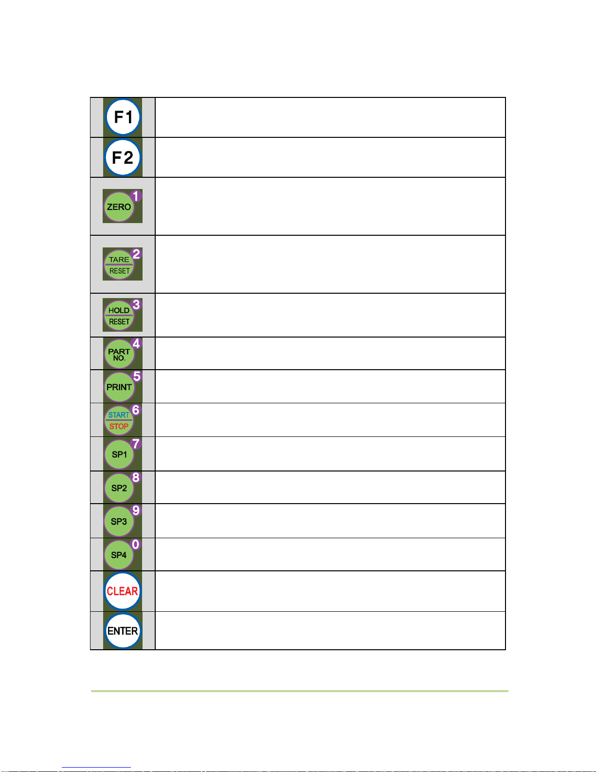
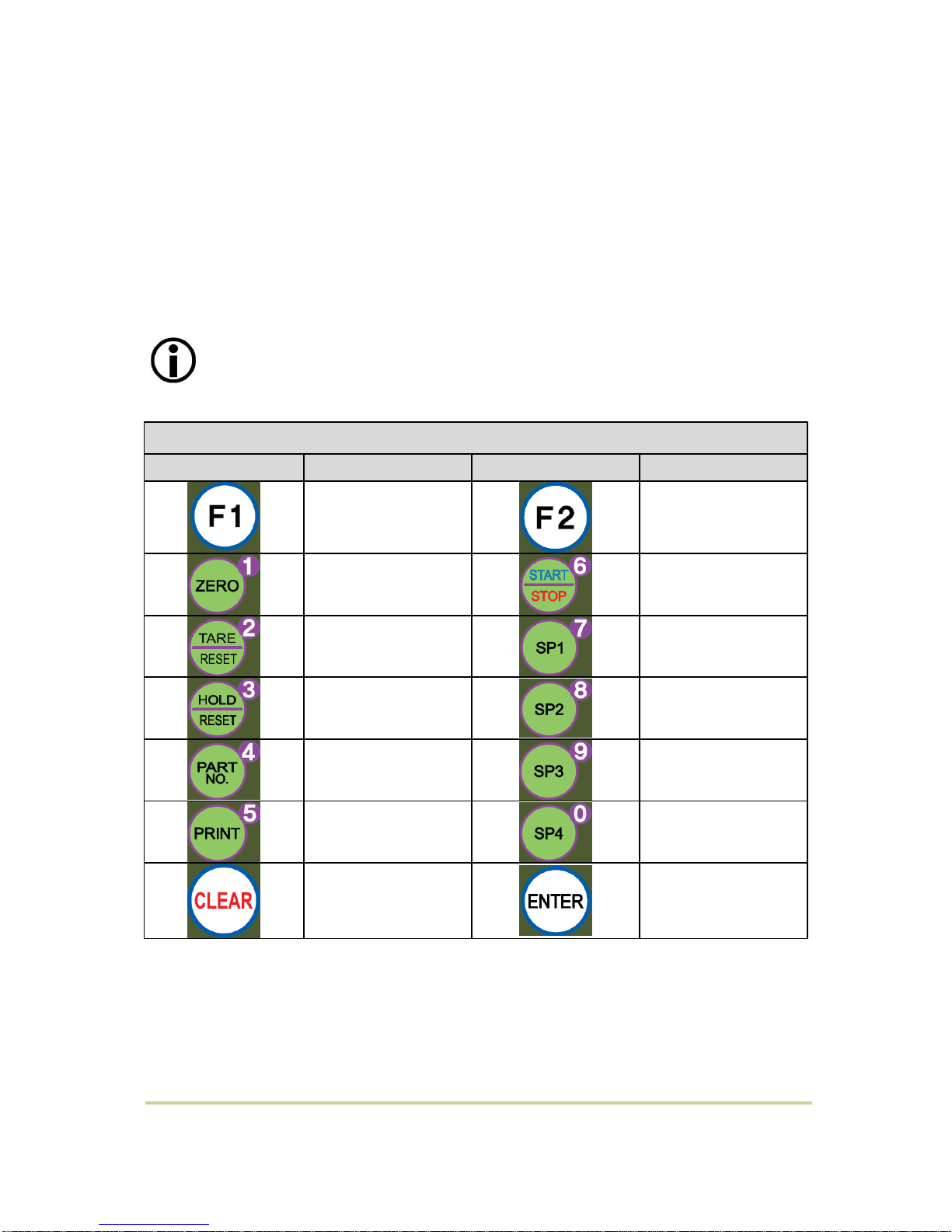
3-3-3. Key Operation
- Press 4 times within 3secs, to enter to Function setting mode.
- Press 4 times within 3secs, to enter to “Hidden function” mode.
- Make the weight value to Zero (It doesn’t work under hold state or weight is near
zero.)
- Enter to function mode in SET-UP mode.
- Number 1
- Set the TARE Function
1st input : “TARE”, 2nd input : “TARE Reset”
(When “HOLD” or weight value is ZERO, then this key doesn’t work.)
- Number 2
- Set the “HOLD” Function
1st input : “HOLD”, 2nd input : “HOLD Reset”
- Number 3
- Product number setting
- Number 4
- Print out
- Number 5
- Make Run or stop weight mode
- Number 6
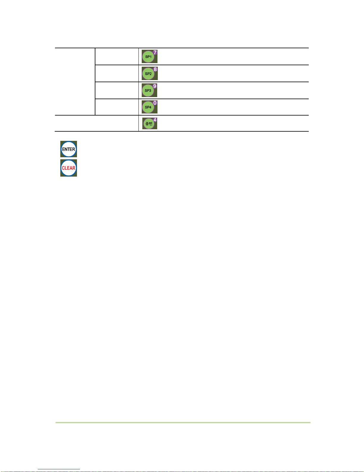
- SP1 set value setting
- Number 7
- SP2 set value setting
- Number 8
- SP3 set value setting
- Number 9
- SP4 set value setting
- Number 0
- Cancel or Move to previous step
- Save and Move to next step
- 9 -
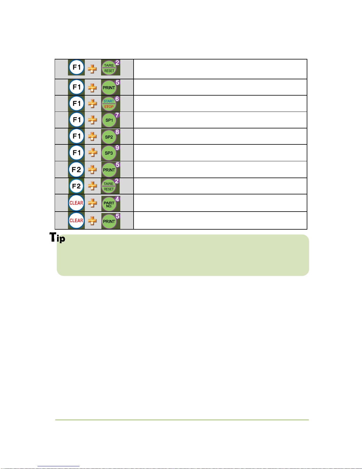
3-3-4. Hot key
Double tare setting
(Once tare is set, Another tare is overlapped.)
Print the Sub-total out
Forced discharge
Display the current weight during 5 secs.
Display the Sub-total weight during 5 secs.
Display the Grand-total weight during 5 secs.
Print the Grand-total out
Input Tare Value(when F530 is set as 01)
Delete the Sub-total weight
Delete the Grand-total weight
Max accumulated weighing count : 999,999times
Over 999,999times return to “0” time
Max accumulated weight display : 999999999 (g, kg, ton)
Over 999,999,999 (g, kg, ton) return to “0” (g, kg, ton)
- 10 -
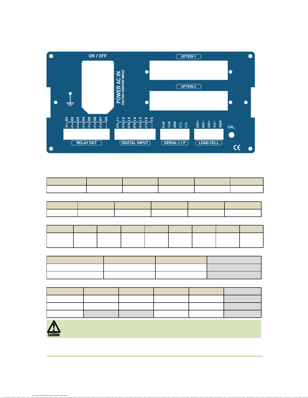
3-4. Rear Panel
(1) AC Power input terminal
(2) External input terminal: User selectable 6EA (Function 156~161)
(3) Serial Interface terminal
Terminal
RxD
TxD
GND
C/L
C/L
RS – 232
Rx
Tx
GND
C/L
C/L
(4) Loadcell Input terminal
Terminal
EXC+
EXC-
SIG+
SIG-
SHLD
Loadcell
EXC+
EXC-
SIG+
SIG-
SHEILD
(5) Relay output terminal: User selectable 7EA (Function 141~147, COM is common)
Terminal
O1
O2
O3
O4
O5
O6
O7
OC
Relay
output
RELAY 1
RELAY 2
RELAY 3
RELAY 4
RELAY 5
RELAY 6
RELAY 7
RELAY
COM
(6) Analog output terminal
Terminal
- +
4~20mA
(-)
(+)
Option
0~10V
(-)
(+)
Option
(7) Option serial interface terminal
Terminal
1 2 3 4
RS – 232C
GND
GND
Rx
Tx
Option
RS - 422
TxD-
TxD+
RxD-
RxD+
Option
RS - 485
Unused
Unused
D-
D+
Option
Please check the Comm. and other specification in the label, attached on the cover
plate first, and make connection according to that information.
- 11 -
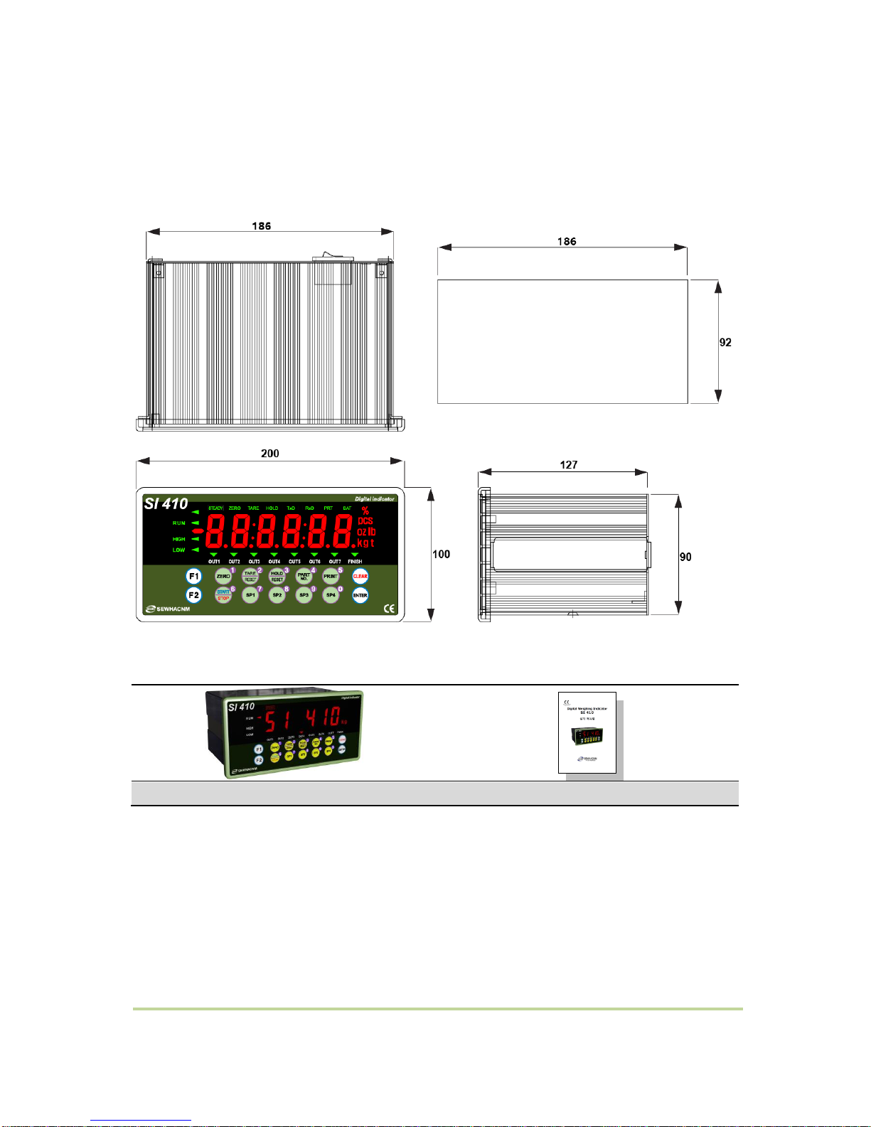
4. Installation
4-1. External Dimension & Cutting Size
4-2. Installation Components
SI 410
User Manual
- 12 -
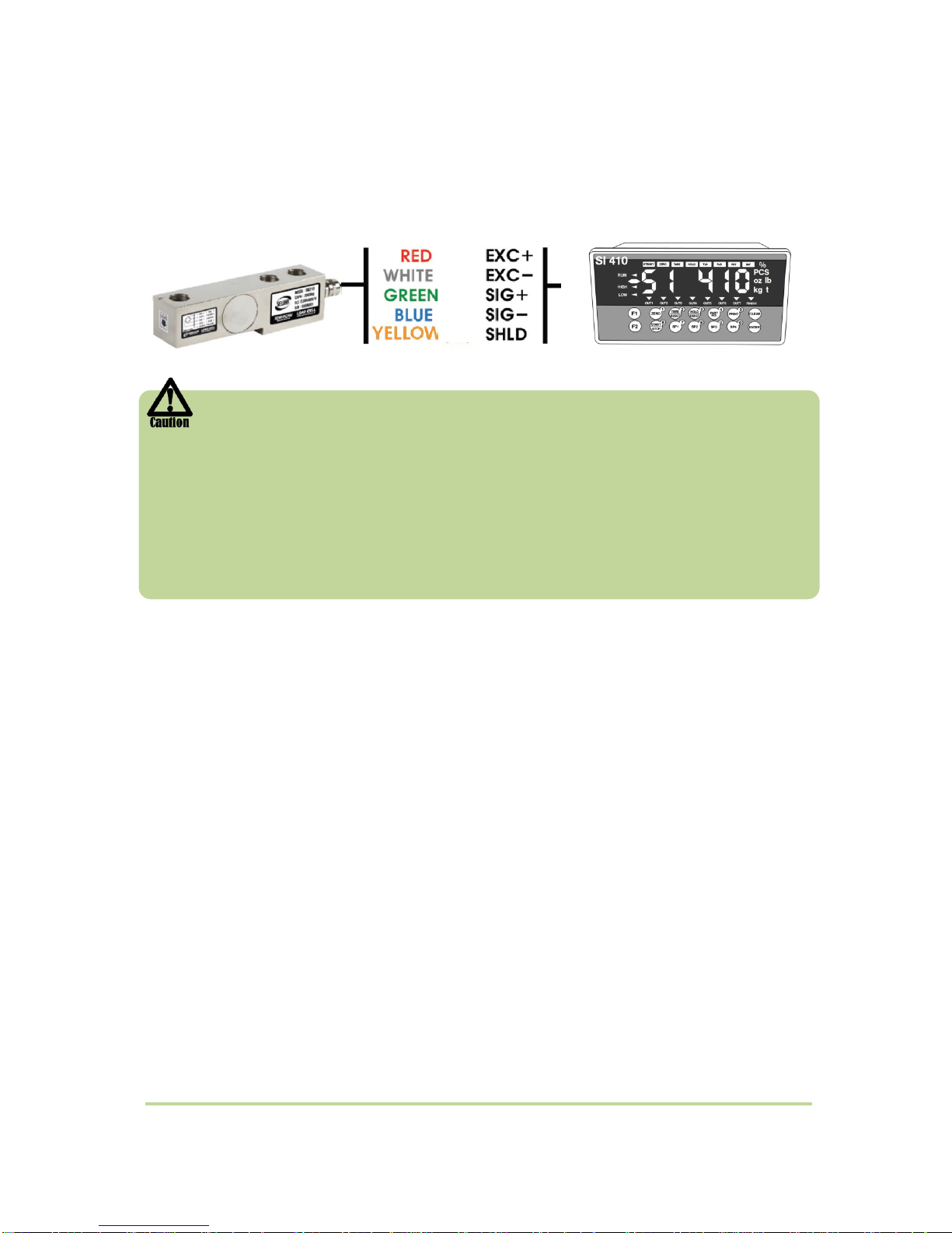
4-3. Load cell Installation
Load Cell Wire Connection (In case of SEWHACNM’s Load cell)
It depends on the manufacturer of load cell, please check the specification.
Under Set-up the Load cell, if EXC+ and EXC- have a short circuit,
It may cause damage in the indicator.(specially analogue board)
If you connect other wires to Load cell terminal wrongly, it may cause damage
in the analogue board.
Before connecting the load cell cable you have to power off and be sure to connect
the cable to the terminal correctly.
Do not weld near the load cells , Indicators or other devices.
■ Load Cell Installation
1. You can connect Max 8pcs of same capacity Load cells at once. (350 Ω)
2. You have to make horizontal balance on the ground.
3. If you install more than 2pcs of load cells, use Summing box and adjust output signal
difference as minimum. It can make wrong weighing process caused by each load cell’s
variation.
4. If there is some temperature difference around Load cell, it can cause wrong weight
measurement.
5. Don’t do Welding job or Arc discharge around installation place. But, there is no choice,
please disconnect power cable and Load cell cable.
6. If you measure static electricity material, please make earth between down part and up part
of Load cell.

- 13 -
5. Set-Up
5-1. Set-up mode
5-1-1. How to enter Set-up mode
Press key for 4 times
If “SET-UP” is displayed, it is complete to
enter the set-up mode.
How to enter each set mode
SET-UP mode
Press key for 4 times
Test
mode
Analog value
Press key for 4 times
Analog Variation
Value
Press key for 4 times
Key
Press key for 4 times
Display
Press key for 4 times
External Input
Press key for 4 times
Relay Output
Press key for 4 times
Analog out
Press key for 4 times
- 14 -
SP set value
SP1 SP2 SP3
SP4
Part Number
* key for saving data..
* key for cancel and go back to previous step.
- 15 -
5-2. Test Weight Calibration Mode (Using test weight)
5-2-1. Calibration
Calibration is the process of adjusting weight balance between "Real Weight" on the Load Cell and
"Displayed weight of Indicator". When you replace Load Cell or Indicator, you have to do
Calibration process once again.
(When you enter the weight calibration mode, tare, hole, print function become initialize.)
Before start to the calibration mode,
Please turn on the indicator and preheat about 15 min.
Calibration key function
Key button
Function
Key button
Function
Setting decimal point
Setting division value
No. 1
No. 6
No. 2
No. 7
No. 3
No. 8
No. 4
No. 9
No. 5
No. 0
Go back to
previous step
Saving data
- 16 -
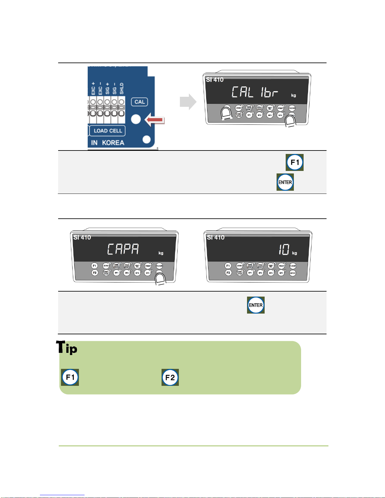
5-2-2. Start Test Weight Calibration Mode
Remove “CAL-BOLT” on the Rear panel,
and press “CAL - LOCK S/W” inside. “
When “CALIBR” displays, press key,
select “WCAL” and press key.
5-2-3. Setting “Capacity of weighing Scale”
If you want to set Max capacity as 1,000kg and the division is 0.1 (100g),
then just input “1000”.
key for going back to zero, key for gradual decrease from unit digit.
After displaying “CAPA”, input max capacity with keys & Press key to save &
move to next step.
- 17 -
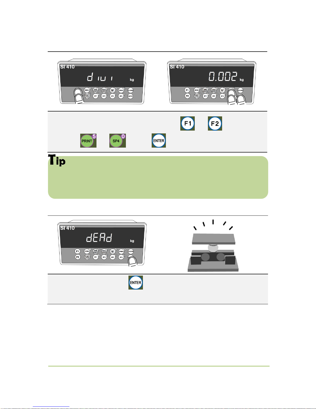
5-2-4. Decimal point and division setting
Max decimal point will be 0.001, and digit can be selected among 1, 2, 5, 10, 20,
50. Digit and decimal point must be fulfilled under the below condition.
(division value / Max capacity value) cannot be over 1/20,000. If this condition is not
fulfilled, “err-1” will be displayed and move back to capacity setting mode.
5-2-5. Measuring the “DEAD” Weight of Weighing Scale
After “DIVI” is displayed, locate the decimal point with and keys, and set the
division with and keys. Press key to save.
When “DEAD” displays, Press key, then indicator will calculate dead weight of
scale part automatically (While this process, there should be nothing on the scale part.)
- 18 -
In this step, if there is unstable condition such as some forces or Vibration on
the scale part, “Error-A” will be displayed, and “DEAD value” will not be calculated.
Please remove the cause of the force or vibration and process it again.
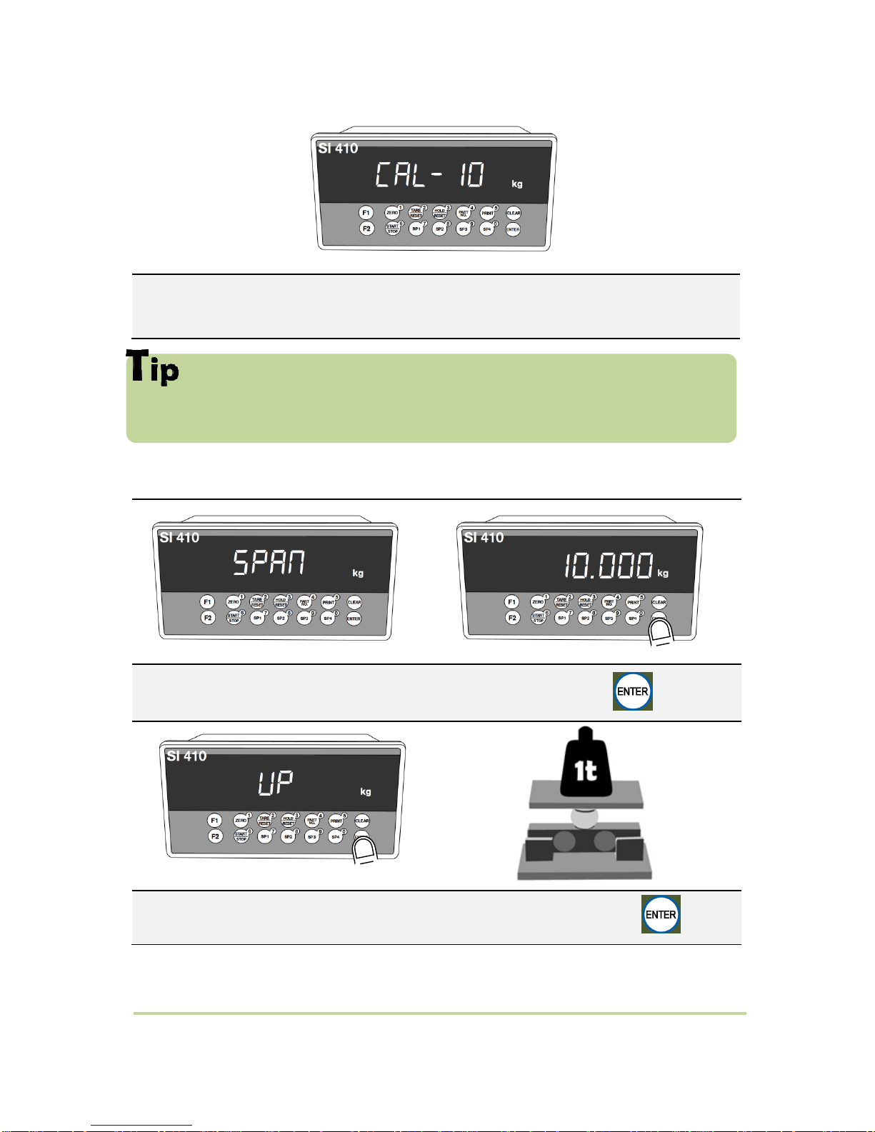
5-2-6. Calculating span value
If the count is over, input the weight of your “Test Weight” and press key.
If “UP” is displayed, please load “Test Weight” on the scale part and press key.
Indicator will search “DEAE weight” during 10secs automatically to find the best
condition.
- 19 -
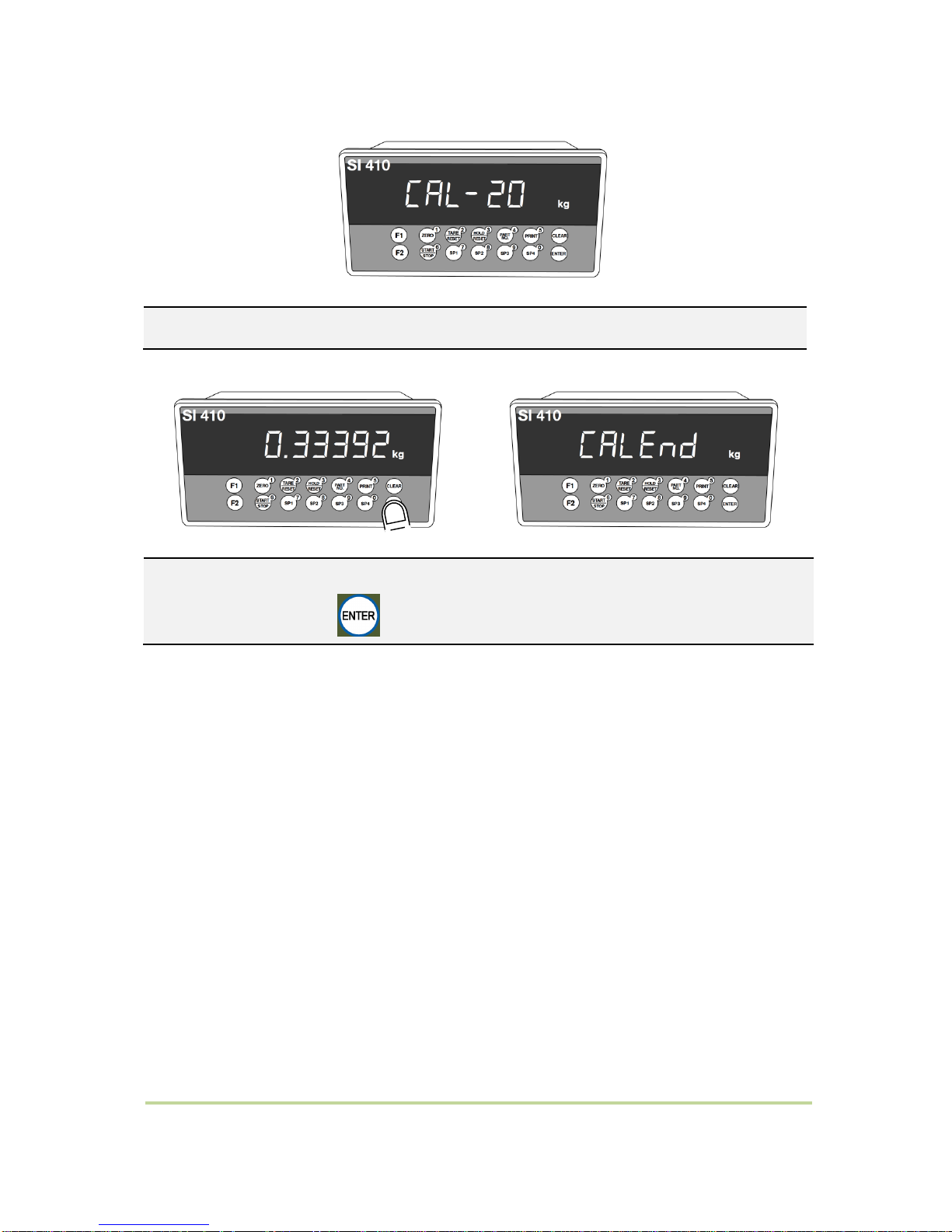
Calculate Span value during 10~20 secs
After calculation, span value will be displayed on
the display. Then press key.
When “CALEND” is displayed and
calibration is completed.
- 20 -
5-3. Simulation Calibration Mode (Calibrate without Test weight)
With this “Simulation Calibration Mode” you can make simple calibration without any
“TEST weight” This calibration mode uses “Load cells’ max capacity” and “Max Output
Rate(mV)”, so the weight adjustment degree might be less than “Test weight Calibration”.
The guaranteed resolution of this “Simulation Calibration” is 1/3,000. HF30 must be set with “01” to
progress simulation calibration mode.
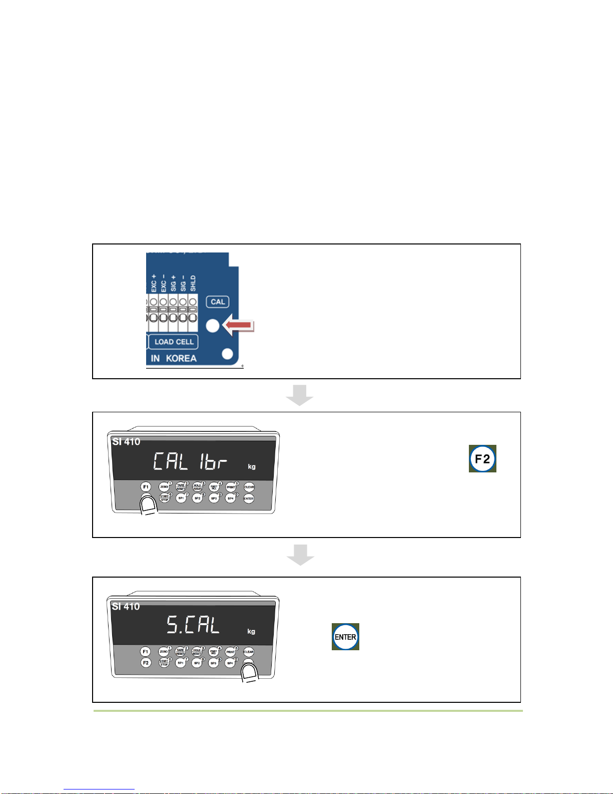
5-3-1. Simulation Calibration Mode Start
Remove “CAL-BOLT” on the rear panel,
and press “CAL - LOCK S/W” inside.
When “CALIBR” is displayed, press
key and select “SCAL”.
Press key to start.
- 21 -
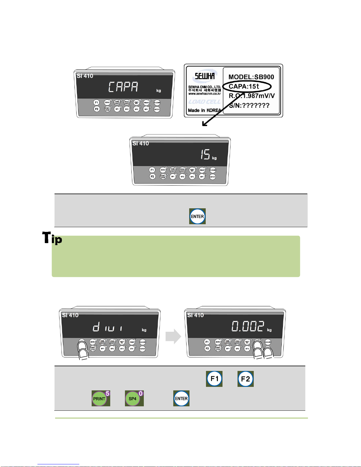
5-3-2. Setting “Capacity of Load Cell”
In case of multiple pieces of load cells are installed, Please make sum of each load cell’s
capacity and make setting with Max Capacity.
EX) There are 4pcs of load cells, and each load cell’s Max capacity is1,000kg.
Then, total Max Capacity will be 4,000kg(1,000 x 4) and you have to input 4,000.
5-3-3. Decimal point and division setting
After “CAPA” displayed, Check Max Capacity of Load cell, Input the Max Capacity of Load cell.
(refer the load cell label, or Test Report.) And press key.
After “DIVI” is displayed, locate the decimal point with and keys, and set the
division with and keys. Press key to save.
- 22 -
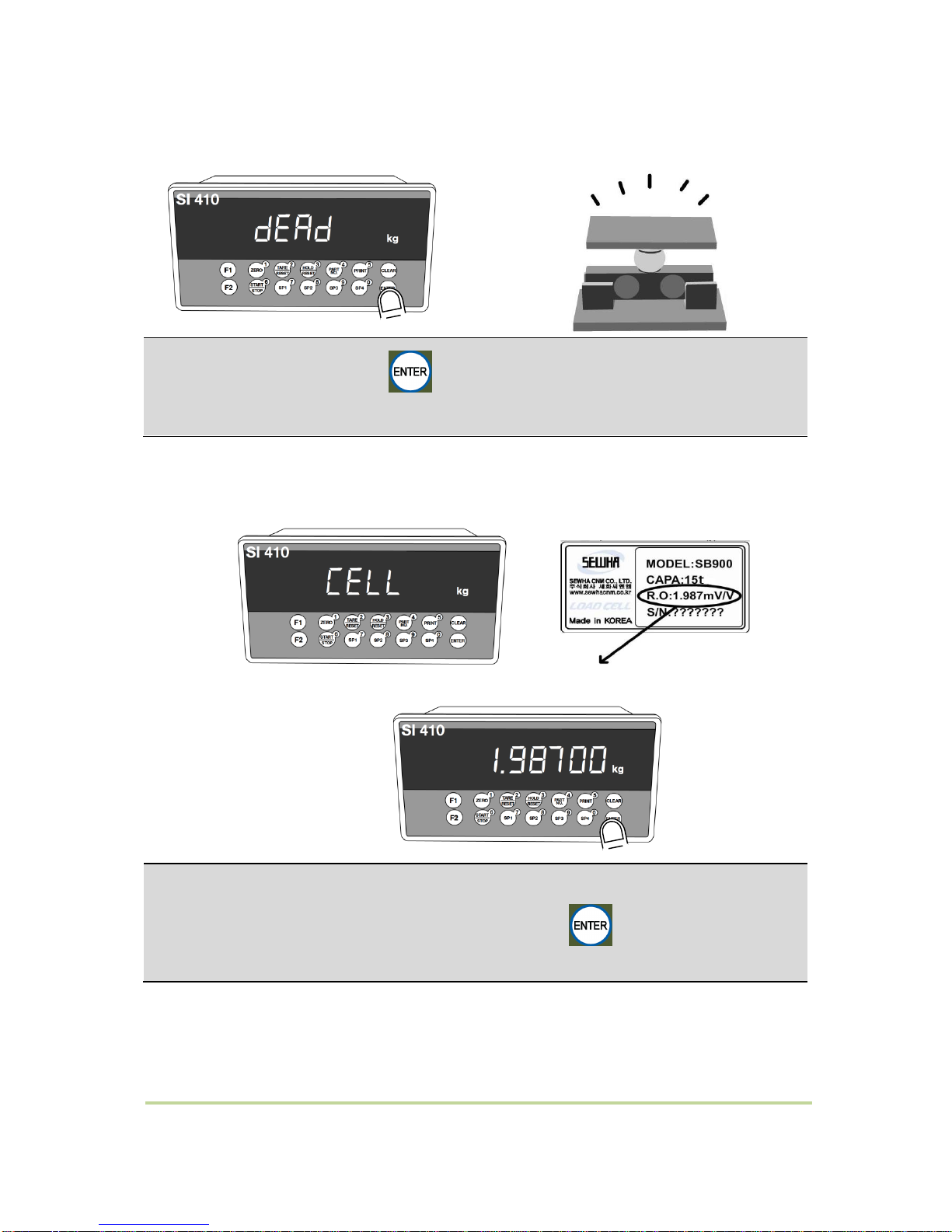
5-3-4. Measuring the “DEAD” Weight of Weighing Scale
5-3-5. Inputting Max Output (Rated Output Voltage / mV)
After “mV/V” is displayed, Check the Rated output value of Load cell.
(Refer to the load cell label, or Test Report). And Press key to save and move to
next step.
When “DEAD” displays, Press key, then indicator will calculate dead weight of
scale part automatically (While this process, there should be nothing on the scale part.)
- 23 -
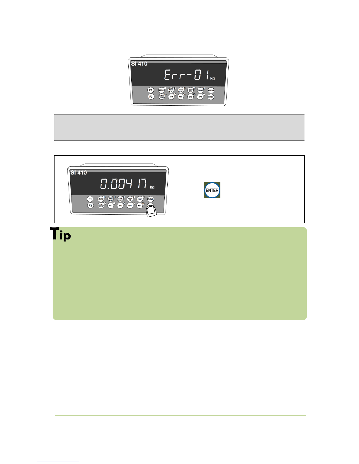
If input wrong value, there will display “Err-01”, please go back to Setting “Capacity of
Load Cell”. After recheck the label of load cell and retry the process.
Calculated span value will be displayed. Then
press key to finish the calibration
step.
In case of multiple pieces of load cells are connected, the rated output will be
same as single Loadcell’s. (Because plural load cells are connected with parallel
connection, the sum of rated output voltage is same as single load cell’s rated output)
※Due to some variation between “State output rate” and “Real Output rate” of load
cell, there might be some weight difference after finishing calibration.
If you want to make more precise weighing process, please measure real output rate of
load cell and input the measured value. Then the weight measurement will be more
precise than before.
 Loading...