

Page 1
Operating
Instructions
Page 2

Measurable success by Sewerin equipment
Congratulations. You have chosen a quality instrument manufactured
by Hermann Sewerin GmbH.
Our equipment will provide you with the highest standards of perfor-
mance, safety and efciency. They correspond with the national and
international guide-lines.
Please read and understand the following operating instructions before
using the equipment; they will help you to use the instrument quickly and
competently. If you have any queries we are available to offer advice
and assistance at any time.
Yours
Hermann Sewerin GmbH
Robert-Bosch-Straße 3
33334 Gütersloh, Germany
Tel.: +49 5241 934-0
Fax: +49 5241 934-444
www.sewerin.com
info@sewerin.com
SEWERIN SARL
17, rue Ampère – BP 211
67727 HOERDT CEDEX, France
Tél. :+33 3 88 68 15 15
Fax :+33 3 88 68 11 77
www.sewerin.fr
sewerin@sewerin.fr
SEWERIN IBERIA S.L.
Centro de Negocios “Eisenhower”
Avenida Sur del Aeropuerto
de Barajas 28, Of. 2.1 y 2.2
28042 Madrid, España
Tel.: +34 91 74807-57
Fax: +34 91 74807-58
www.sewerin.es
info@sewerin.es
Sewerin Ltd
Hertfordshire
UK
Phone: +44 1462-634363
www.sewerin.co.uk
info@sewerin.co.uk
Sewerin Sp.z o.o.
ul. Twórcza 79L/1
03-289 Warszawa, Polska
Tel.: +48 22 675 09 69
Faks: +48 22 486 93 44
Tel. kom. +48 501 879 444
www.sewerin.pl
info@sewerin.pl
Page 3
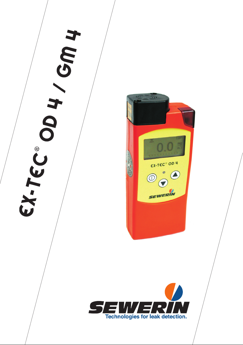
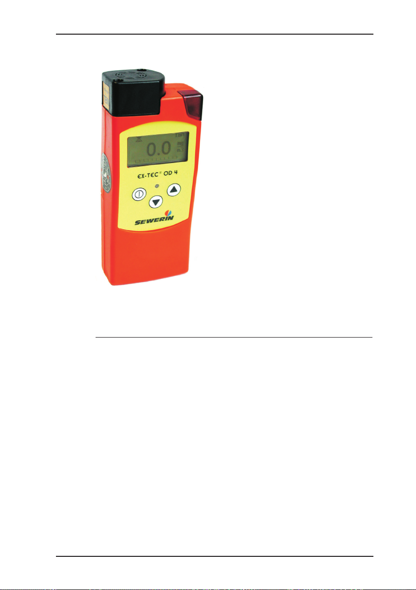
EX-TEC OD 4
®
0.0
THT
mg
m3
Sensor head
Attachment
Alarm lamp
LCD
Buzzer
Keypad
Charging contacts
Illustration EX-TEC OD 4
Page 4
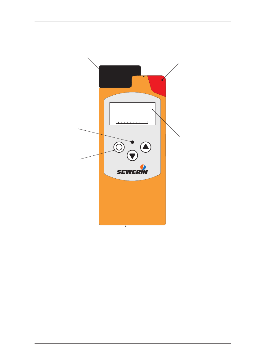
Illustration EX-TEC GM 4
Sensor head
Attachment
Alarm lamp
LCD
Buzzer
Keypad
Charging contacts
H2
Battery state
1500
EX-TEC GM 4
Activation
Alarm thresholds
1500
PPM
®
H2
PPM
Type of gas
Gas concentration
Unit
Trend bar
Page 5

Operating Instructions
EX-TEC® OD 4/GM 4
20.04.2016 a – V1.XXX – 103955 – en
Page 6
For your safety
This product may only be operated by appropriately-trained persons who
are familiar with the relevant operating manual.
It may only be used for its designated purpose, i.e. for industrial and commercial use.
Repair work may only be carried out by specialists or by persons who have
undergone appropriate training.
Any alterations or modications to the product require the prior approval of
Hermann Sewerin GmbH. In the event of unauthorised alterations to the
product the manufacturer accepts no liability for damage.
Only Hermann Sewerin GmbH accessories may be used with the product.
Only spare parts approved by us may be used for repairs.
Hermann Sewerin GmbH accepts no liability for damage resulting from
non-compliance with the foregoing. The guarantee and liability provisions
in the Hermann Sewerin GmbH terms of sale and supply are not extended
by the foregoing.
We reserve the right to make changes in the context of continued technical development.
In addition to these instructions, please comply with generally applicable
safety and accident-prevention regulations.
Symbols used:
CAUTION:
Note:
This symbol warns of dangers that may threaten
the safety of the user or maty damage or destroy
the product.
This symbol ags information and hints extending
beyond the actual operation of the product .
Page 7

Contents Page
1 EX-TEC OD 4/EX-TEC GM 4 system ......................................1
1.1 The EX-TEC OD 4 system ........................................................1
1.1.1 Before starting work ...............................................................1
1.1.2 The need for gas odorisation .................................................1
1.1.3 Measurement principle ........................................................... 1
1.1.4 Boundary conditions for measurement and sampling .............. 2
1.1.5 EX-TEC OD 4 ............................................................................3
1.1.6 Test certicates ......................................................................4
1.2 EX-TEC GM 4 system ............................................................... 5
1.2.1 Test certicates ......................................................................5
2 Safety .......................................................................................6
2.1 Safety instructions ..................................................................... 6
3 Measuring operation ............................................................... 8
3.1 Switching on .............................................................................. 8
3.2 Operating modes ..................................................................... 11
3.3 Alarms .....................................................................................16
3.4 Illumination and operating-hours display ................................. 18
3.5 Battery alarm ........................................................................... 18
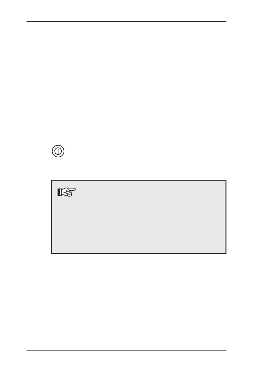
3.6 Switching off ............................................................................19
4 Charging and battery operation ........................................... 20
4.1 Charging and charge maintenance when using NiMH batteries ... 20
4.2 Self-dischargeand battery care ...............................................22
4.3 Battery operation ..................................................................... 23
4.4 Instruments showing serial number 062 00 ............................24
5 Testing the instrument .......................................................... 25
5.1 Testing/upkeep ........................................................................25
5.2 Test set ....................................................................................27
5.2.1 EX-TEC GM 4 ......................................................................27
5.2.2 EX-TEC OD 4 ....................................................................... 28
5.3 Test gases ...............................................................................29
5.4 Testing the pump, zero point and display accuracy ................30
I
Page 8

Contents Page
6 Info menu ...............................................................................33
6.1 Menu structure ........................................................................33
6.2 Overview .................................................................................34
7 Adjustment menu .................................................................. 36
7.1 Menu structure ........................................................................36
7.2 Sensor adjustment ..................................................................36
7.2.1 Setting the H2-sensor ...........................................................36
7.2.2 Setting the O2 sensor ...........................................................37
7.3 Setting the test gas concentration ........................................... 38
7.4 Inspection conrmation ...........................................................40
7.5 Leaving the adjustment menu ................................................. 40
8 System menu ......................................................................... 41
8.1 Menu structure ........................................................................41
8.2 Setting the date and time ........................................................42
8.3 Setting the inspection intervall ................................................43
8.4 Setting the inspection block ....................................................46
8.5 Setting the PIN ........................................................................47
8.6 Setting the alarm thresholds ...................................................48
8.7 Setting the user name .............................................................51
8.8 Setting the language ...............................................................53
8.9 Leaving the system menu .......................................................53
9 Hardware menu .....................................................................54
9.1 Menu structure ........................................................................54
9.1.1 EX-TEC GM 4 ......................................................................54
9.1.2 EX-TEC OD 4 .......................................................................55
9.2 Setting the battery type ...........................................................56
9.3 Setting the illumination time and contrast ...............................57
9.4 Autostart ..................................................................................58
9.5 Range .....................................................................................59
9.6 Changing the sensor ...............................................................59
9.6.1 Gas ....................................................................................... 60
9.6.2 Sensor installation ................................................................ 60
9.7 Setting pump operation ...........................................................61
9.8 Carrying out an LCD test ......................................................... 61
II
Page 9

Contents Page
9.9 Restoring the factory settings .................................................. 62
9.10 Leaving the hardware menu ....................................................63
10 Memory menu ........................................................................ 64
10.1 Menu structure ........................................................................64
10.2 Clearing memory .....................................................................64
10.3 Setting the memory interval ....................................................65
10.4 Leaving the memory menu ......................................................65
11 Technical aspects..................................................................66
11.1 Technical notes .......................................................................66
11.2 Technical data .........................................................................68
11.3 Error messages ....................................................................... 79
11.4 Consumables .......................................................................... 80
11.5 Hints on Disposal .................................................................... 81
12 Delivery variants and accessories ......................................82
12.1 Delivery variants ......................................................................82
12.2 Accessories .............................................................................84
13 Appendix ................................................................................90
13.1 EU-declaration of conformity ...................................................90
13.2 Inspection protocol ..................................................................91
13.3 EX-TEC OD 4/GM 4 operating instructions in brief ................. 92
III
Page 10

1 EX-TEC OD 4/EX-TEC GM 4 system
1 EX-TEC OD 4/EX-TEC GM 4 system
The EX-TEC OD 4 is a combined warning and measuring instru-
ment for determining odorant concentration. It is available with
either a THT or a TBM sensor.
The EX-TEC GM 4 is a warning and measuring instrument that
detects oxygen and various toxic gases.
1.1 The EX-TEC OD 4 system
1.1.1 Before starting work
Adequate gas odorisation is an important criterion for safe network
operation. Please take careful note of the following information.
1.1.2 The need for gas odorisation
Natural gas is odourless. So that even the smallest leaks in indoor
installations or elsewhere in a gas-distribution network can be
immediately detected, the gas is odorised: a strong-smelling substance is added to it. The substances used are organic sulphur
compounds and acrylates. The most widespread currently being
tetrahydrothiophene (THT) and tertiary butyl mercaptan (TBM).
DVGW worksheet G 280 sets the minimum values for odorant
concentration at 10 mg of THT / m3 and 3.8 mg of TBM / m3. This
worksheet also requires the operator of a distribution network to
check and document the odorant concentration at least once a
year.
1.1.3 Measurement principle
The EX-TEC OD 4 contains an electrochemical sensor that reacts
to the smallest traces of sulphur compounds. This produces elec-
trical signals, which are then processed by the integral electronic
system. The intensity of the signal varies directly with the strength
of the concentration.
1
Page 11

1 EX-TEC OD 4/EX-TEC GM 4 system
The sensor is lled with a liquid (electrolyte), which makes it very
sensitive to high temperatures. The maximum storage temperature of 40 °C must therefore not be exceeded. Electrochemical
processes constantly take place inside the measurement cell,
requiring the EX-TEC OD 4 to be permanently supplied with battery power at an adequate voltage. For this reason the integral
batteries must not be permitted to reach a state of deep discharge.
When the instrument is not in use it should therefore be stored
in charge-maintenance operation (see section 4.1: Charging and
charge maintenance when using NiMH batteries).
1.1.4 Boundary conditions for measurement and sampling
As well as all sulphur compounds, the electrochemical measurement cell also reacts very strongly to moisture. Even though this
is rarely important when carrying out measurements in a gasdistribution network, operators should not blow through sampling
hoses to clear them.
When sampling it is essential to ensure that there are no connecting pieces made of rubber or synthetic substances between the
EX-TEC OD 4 and the connection to the gas main unless these
consist of inert materials (e.g. Viton or nylon).
A further factor that affects the measurement of sulphur com-
pounds with the EX-TEC OD 4 is the ow rate through the mea-
surement chamber, which must always exceed 20 l/h. Only the
connection hoses supplied with the instrument should therefore
be used for sampling.
2
Page 12
1.1.5 EX-TEC OD 4
The following sensors are available:
1 EX-TEC OD 4/EX-TEC GM 4 system
The EX-TEC OD 4 is a hand-held
instrument for the measurement
of tetrahydrothiophene (THT) or
tertiary butyl mercaptan (TBM). It
is available in pump and diffusion
versions.
Sensor
THT
TBM
range principle
0 –100 mg/m
0 –100 mg/m
3
3
electrochemical
electrochemical
3
Page 13

1 EX-TEC OD 4/EX-TEC GM 4 system
1.1.6 Testcerticates
Passive explosion protection
The EX-TEC OD 4 has been tested for explosion protection in
accordance with European norms (CENELEC):
EC prototype test certicate: TÜV 01 ATEX 1657
Identication: II2G Ex e ib IIB T4 Gb
Testing institution: TÜV NORD CERT GmbH,
Hannover
4
Page 14

1.2 EX-TEC GM 4 system
The EX-TEC GM 4 is a gas-measurement and warning instru-
ment. It is available in pump and diffusion versions. A different
sensor is used for each gas.
The following electrochemical sensors are available:
Sensor range
Carbon monoxide CO 0 – 500 ppm
Hydrogen H2 0 – 1.0 vol.%
Hydrogen sulphide H2S 0 – 100 ppm
Hydrogen sulphide H2S 0 – 2000 ppm
Ammonia NH3 0 – 100 ppm
Oxygen O2 0 – 25 vol.%
Hydrogen chloride HCI
1.2.1 Testcerticates
Passive explosion protection
The EX-TEC GM 4 has been tested for explosion protection in
accordance with European norms (CENELEC):
1 EX-TEC OD 4/EX-TEC GM 4 system
0 – 30 ppm
EC prototype test certicate: TÜV 01 ATEX 1657
Identication 1: II2G Ex e ib IIB T4 Gb
basic instrument without
leather case for all gases
except hydrogen H
2
Identication 2: II2G Ex e ib IIC T4 Gb
basic instrument with leather
case for all gases including
hydrogen H
2
Testing institution: TÜV NORD CERT GmbH,
Hannover
5
Page 15
2 Safety
2 Safety
2.1 Safety instructions
CAUTION!
Always use original SEWERIN accessories with the
EX-TEC OD 4/GM 4!
CAUTION!
Observe the permissible operating temperature
range of minus 10 °C to plus 40 °C!
(with some sensors the temperature range may be
wider - see section 11.2: Technical data)!
CAUTION!
The EX-TEC OD 4/GM 4 must not be recharged or
its battery compartment opened in areas exposed
to the danger of explosion!
CAUTION!
Test gases may only be used in well-ventilated
spaces!
CAUTION!
The EX-TEC OD 4/GM 4 satises the limits of the
EMV regulation. When using it near (mobile) radio
equipment please also observe the instructions in
the manuals for that equipment!
6
Page 16

CAUTION!
Please note that when the EX-TEC OD 4/GM 4 is
in measuring operation the gas sample is released
into the ambient air through its outlet.
Special care must be taken to ensure that this does
not produce an explosive or toxic gas mixture, espe-
cially during use in conned spaces. It may therefore
be necessary to use a gas-warning device to monitor
the ambient air.
CAUTION!
The EX-TEC GM 4 with the hydrogen sulphide H2S
sensor (0 – 2000 ppm) is a pure measuring instru-
ment: the „warning“ operating mode is not available.
Please note that the human sense of smell fails at
concentrations of 100 ppm of H2S and above. Concentrations of over 500 ppm of H2S lead to very seri-
ous damage to health, uncoordinated movements,
unconsciousness, respiratory failure and death. It is
thus essential to ensure that the lower toxic limit of
10 ppm in the ambient air is not exceeded!
2 Safety
CAUTION!
When using the H2 sensor the HG4 must be in its
leather case (to provide explosion protection)!
7
Page 17
3 Measuring operation
V1.001
EX-TEC GM4
H2
3 Measuring operation
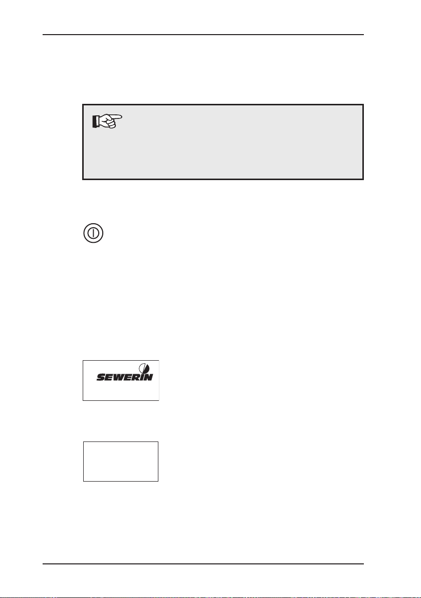
3.1 Switching on
Note:
This operating manual describes the functions
of software version 1.XXX. Other versions may
involve changes.In this event please consult any
page insertions.
z always switch the instrument
on in „fresh air“
z hold the on/off key down for
about 3 seconds
z the optical and acoustic control
signals (items 1 and 7) operate
for about 3 seconds
z the LC display illumination
automatically switches on
z pump instruments: the inte-
gral pump runs at constant
power
Opening screen
z display of:
- version number (V1.001)
- instrument type (GM 4)
- sensor type (H2)
8
27.11.2000
12:37
Stadtwerke GT
Heinz Muster
Abt. TDLL 24.4
Date/time
z display of:
- date (27.11.2000)
- time (12:37)
- user name
z properly-set values are impor-
tant for the documentation of
your readings
Page 18

3 Measuring operation
Sensor install.
12.06.2002
durability
24 Monate
H2
0...1,00 Vol%
z you can correct any variances
(cf. section 8.2: Setting the
date/time)
Instrument settings
The EX-TEC OD 4/GM 4 defaults
to a set operating mode at switchon, which you can change (cf.
section 9.4: Autostart). The
operating mode is factory-set to
„Measurement“:
z display of:
- battery-charge level
- gas (here: H2)
- operating mode
(here: measurement)
- range
(here: 0 – 1.00 vol.%)
Other possible settings can be
found in section 9.4: Autostart.
z display of the day the sensor
was tted
z display of expected sensor
life
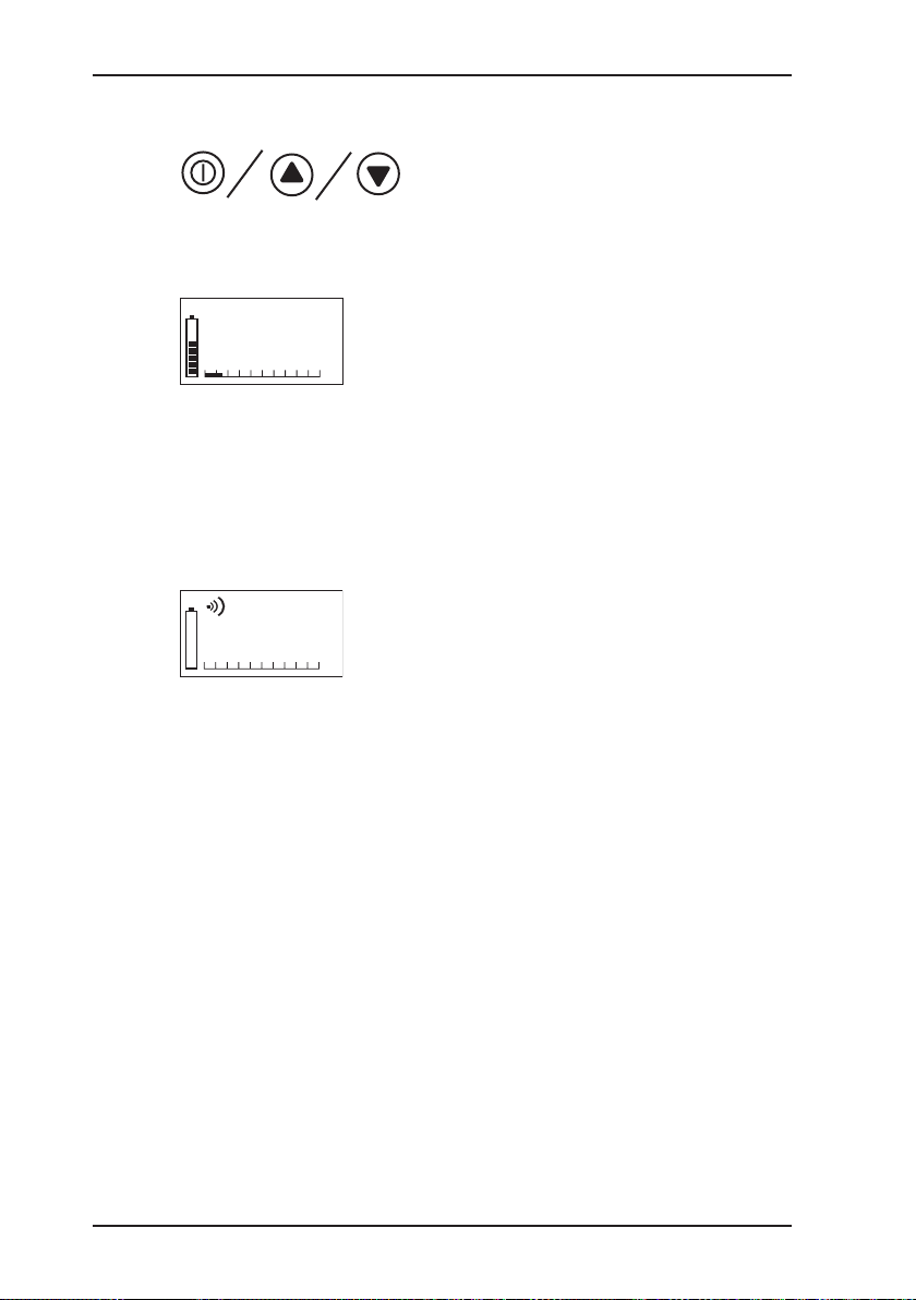
Symbols
z available operating hours are
displayed (5 hours = 5 bars)
symbol: battery
z measurement is under way
(symbol eggtimer)
z all alarm thresholds are acti-
vated
symbol: alarm threshold
9
Page 19
3 Measuring operation
Next scheduled inspection
(display optional)
z if you have set an inspec-
tion interval, the next scheduled inspection date (e.g.
11.03.2004) is displayed for
about 3 seconds (cf. section
8.3: Setting the inspection
interval))
z depending on the current and
inspection dates, the intermittent or continuous alarm may
also be triggered (items 1
and 7)
z clearing the alarm with the
on/off key or waiting for 15
seconds switches to measuring operation
Note:
If the EX-TEC OD 4/GM 4 now automatically
switches off, the inspection date has passed with
the inspection block switched on (cf. section 8.0:
System menu).
The instrument does not revert to measuring opera-
tion until an inspection has been carried out and
conrmed.
10
Page 20
3.2 Operating modes
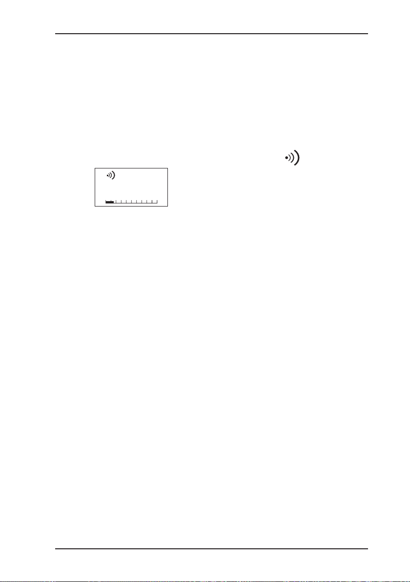
WARNING
z Warning of high gas concentration in buildings and the work-
ing environment
z Testing enclosed spaces
H2
1500
PPM
3 Measuring operation
z all alarm thresholds are acti-
vated
NB:
z the current gas concentration
is displayed:
- as a gure
(e.g.: 1500 PPM H2)
- as a trend bar
z every 5 seconds an operating
signal - both acoustic (item 7)
and optical (item 1) - is emitted
to conrm that the instrument
in functioning in the warning
operating mode. If this operating signal is not emitted,
you cannot be sure that the
gas concentration is being
properly monitored and must
leave the endangered area
without delay.
11
Page 21
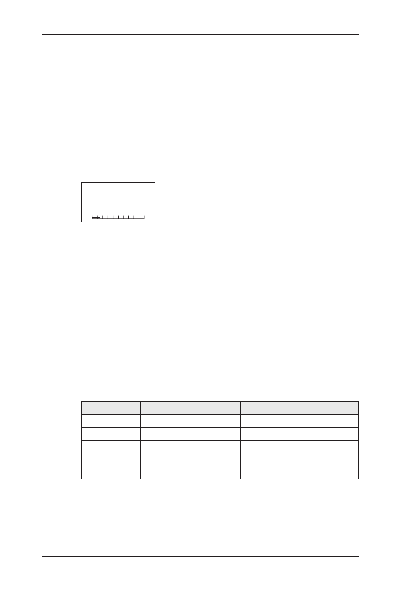
3 Measuring operation
H2
PPM
1500
MEASUREMENT
EX-TEC GM 4:
z Testing the gas concentration in buildings
z Measuring gas concentrations in pipes and elsewhere
z Searching for leaks in pipes in buildings
z Checking joints, e.g. weld seams
z Carrying out building tests
z Checking enclosed spaces
EX-TEC OD 4:
z Determining the odorant concentration in natural gas
z Measuring the odorant concentration in the air in odorising
plants
z Before sampling observe the sufcient ush of intake
z the current gas concentration
is displayed:
- as a gure
(e.g.: 1500 PPM H2)
- as a trend bar
12
Sampling hoses
To ensure that the sample always passes through the
EX-TEC OD 4 at an adequate rate, there are different sampling
hoses for each of the possible pressure ranges. These are colourcoded as follows:
Colour Pressure range Part-Nr.
black 20 – 50 mbar OD04-Z0100
blue 50 – 125 mbar OD04-Z0200
green 125 – 400 mbar OD04-Z0300
yellow 400 – 1000 mbar OD04-Z0400
red 1 – 2 bar OD04-Z0500
(further on request)
Measurements are only reliable if the original Sewerin-supplied
hoses are used.
Page 22
Switching operating modet
H2
0...1,00 Vol%
H2
0...1,00 VOL%
AL1 0,4 VOL%
AL2 0,8 VOL%
pin point:
0001
pin point: 0001
02.07.02 13:58
1500 PPM
3 Measuring operation
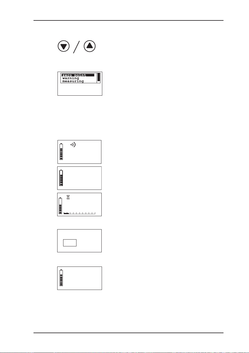
z holding down one of the cursor
keys for about 2 seconds
brings you to operating mode
selection
z use the cursor keys to select
one of the items:
Zero point
in the currently selected mea-
surement range zero-point
correction can be carried out
if necessary (temporary zero-
point adjustment within certain
limits)
Warning
selects the WARNING operating mode
Measurement
selects the MEASUREMENT
operating mode
1500
â
â
H2
PPM
Saving
The gas concentration measured can be saved and
assigned to a measurement
location. After the number of
the measurement location
has been entered, the measurement location, date, time
and reading are displayed
together once again. These
data can subsequently be read
out and analysed with the PC
analysis software (available
separately).
13
Page 23

3 Measuring operation
z then press the on/off key to
conrm your selection
Note:
If the selection is not conrmed with the on/off key,
the instrument reverts to its previous operating mode
after about 10 seconds!
14
Page 24
3 Measuring operation
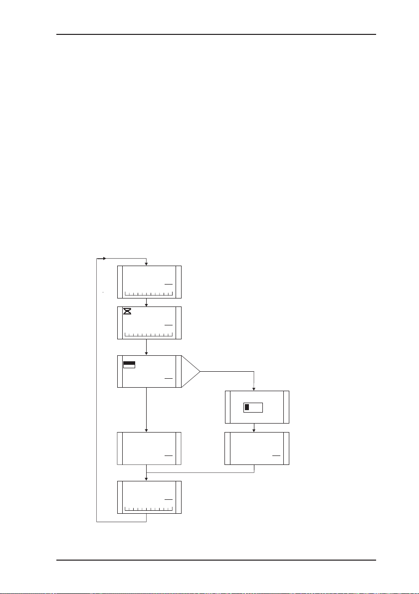
Starting measurement (only possible on the EX-TEC OD 4 in
the „Measurement“ operating mode)
z A measurement can also be started by briey pressing the
on/off key.
z Indication when measurement is under way: eggtimer
symbol.
z Measurement is halted on the expiry of the measurement dura-
tion (about 3.5 minutes) or when the reading has stabilised.
z When measurement is complete the reading can be assigned
to a measurement location and saved.
z These data can subsequently be read out and analysed with
the PC analysis software (available separately).
z If no measurement location is entered within 10 seconds, the
measurement is lost.
0.0
0.0
store
Yes
No
16.5
pin point: ----
5.4.2002 8:50
16.5
14.5
THT
mg
m3
THT
mg
m3
mg
m3
mg
m3
THT
mg
m3
Possibilities to start measuring:
1) choose menu and start measuring
2) press on-key shortly
Cancel measuring:
1) press on-key shortly
2) choose menu and stop measuring
pin point:
0
012
pin point: 0012
5.4.2002 8:50
mg
16.5
m3
Time-out: 60 seconds
Time-out: 10 seconds
Measuring value remains
for 20 seconds
15
Page 25

3 Measuring operation
H2
AL1
VOL%
0,4
3.3 Alarms
In the WARNING operating mode the EX-TEC OD4/GM 4 has
various alarm thresholds:
EX-TEC OD 4
Example: TBM
AL1 alarm threshold 1 = 10 mg/m
AL2 alarm threshold 2 = 20 mg/m3
EX-TEC GM 4
Example: H2 (factory setting)
AL1 alarm threshold 1 = 4000 ppm
AL2 alarm threshold 2 = 8000 ppm
3
AL1 alarm (example: H2)
z if this alarm threshold is
exceeded, the result is:
- optical alarm (item 1)
- acoustic alarm (item 7) at
2 Hz
- LCD (item 2) lights up
- AL1 appears in the LCD
z the 2 Hz intermittent tone is
quite different from the operating signal
z the acoustic AL1 alarm can
be cleared by briey pressing
the on/off key, but the optical
alarm (item 1) continues
z if the concentration falls below
this alarm threshold, the optical and acoustic alarms (items
1 and 7) switch off
16
Page 26

3 Measuring operation
H2
AL2
VOL%
0,8
AL2-alarm (example: H2)
z if this alarm threshold is
exceeded, the result is:
- optical alarm (item 1)
- acoustic alarm (item 7) at
5 Hz
- LCD (item 2) lights up
- AL2 appears in the LCD
z the rapid intermittent tone at
5 Hz is quite different from the
operating signal
z the AL2 alarm cannot be
cleared
z if the concentration falls below
this alarm threshold, the alarm
becomes an AL1 alarm, which
can be cleared
17
Page 27
3 Measuring operation
0
3.4 Illumination and operating-hours display
z pressing any key switches the
LCD illumination on
z ou can also adjust the illumina-
tion time individually (cf. sec-
tion 9: Hardware menu)
z when the illumination comes
on the remaining operating
hours (e.g. 5 hours) are displayed
z this display (battery symbol
and bars) and the illumination
switch off automatically after
about 10 seconds
z the battery symbol appears in
the LC display and the operating signal sounds at twice
its normal rate
z you now have at least another
15 minutes' operating time
available
z after that the instrument must
be charged (cf. section 4:
Charging and battery opera-
tion)
1500
3.5 Battery alarm
H2
PPM
H2
PPM
18
Page 28

3.6 Switching off
3 Measuring operation
z hold down the on/off key for
about 3 seconds
z the optical and acoustical
control signals (items 1 and
7) are activated for about 3
seconds
z remaining operating hours are
displayed in the form of the
battery symbol and bars (e.g.
5 hours = 5 bars)
19
Page 29
4 Charging and battery operation
4 Charging and battery operation
CAUTION!
The EX-TEC OD 4/GM 4 must not be recharged or
its battery compartment opened in an area exposed
to the danger of explosion
4.1 Charging and charge maintenance when using NiMH batteries
Batteries should be approximately at room temperature for charging.
Charging
After 12 hours‘ charging the instrument has about 20 hours of oper-
ation with the pump running or about 50 hours of operation in diffusion operation.
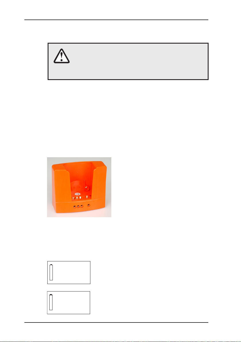
The docking station HG4 is required for charging. It can be used
either in the workshop or in the emergency vehicle.
The docking station has the following connections on its side:
z AC/DC adapter M4 for
100 – 240 V~
z Vehicle cable M4 12 V= mount-
ing
z Vehicle cable M4 12 V=
mobile
z Vehicle cable M4 24 V= mount-
ing
z You can operate up to 5 dock-
ing stations with one 100 – 240
V~ AC/DC adapter M4
z With more than 5 stations the
charg. volt.
too low
charg. volt.
too high
charging voltage is insufcient.
An error message is displayed
to that effect
z if you connect the docking sta-
tion directly to a 24-V network in
the vehicle, the voltage will be
too high for proper charging
20
Page 30

4 Charging and battery operation
04
Place the EX-TEC OD 4/GM 4 in the docking station and a display
on the following lines appears:
z the instrument now has 5
operating hours left (= 5 bars)
and needs another 4 hours to
reach full charge
z if it is fully charged, all the bars
appear and the digital display
disappears
Charge maintenance
Once the instrument is fully charged, it switches automatically to
charge maintenance. It can be left in the docking station until the
next time it is needed.
21
Page 31

4 Charging and battery operation
4.2 Self-dischargeand battery care
If the instrument is not placed in the charging adapter when it is
switched off, this will cause the nickel/metal-hydride battery to
self-discharge, reducing the remaining operating time.
After a maximum of 30 days the instrument indicates no remain-
ing operating hours and it must be recharged.
Note:
Brief periods of use and protracted disuse may in
the long term lead to the so-called „memory effect“,
which means that the actual battery capacity available is less than what is shown in the display.
You can counteract this by fully discharging the
EX-TEC OD 4/GM 4 regularly (e.g. once a month)
and then recharging it.
Switch the instrument on and place it in the docking
station. When it is fully discharged, charging begins
automatically. The entire process takes:
22
20 h (typical discharge, pump instrument)
+ 12 h (full charge)
= 32 h
Page 32

4.3 Battery operation
charge aborted
Alcalinebattery
With new non-rechargeable alkaline batteries the EX-TEC OD 4/
GM 4 will operate for 20 hours with the pump running or 50 hours
in diffusion operation.
Changing the batteries
When the batteries need to be changed, the battery compartment
can be opened with the screwdriver supplied (the two lower screws
on the back of the instrument). Insert the new cells the right way
round (as marked) and close the battery compartment again.
Once the old batteries are removed the date and time are preserved in the instrument for about 120 seconds. If the battery
change takes longer than this, you will have to re-enter both values
next time it is switched on. No other data will be lost.
The value for the operating-hours display for nickel/metal-hydride
batteries is lost if these are replaced by alkaline batteries, so if
nickel/metal-hydride batteries are inserted again they must rst
be fully discharged and then recharged. This ensures that the
available operating hours will be correctly displayed.
4 Charging and battery operation
z An EX-TEC OD 4/GM 4 tted
with non-rechargeable alkaline
batteries cannot be charged.
If you try to do so a warning
message is displayed and the
instrument must be removed
from the docking station.
23
Page 33

4 Charging and battery operation
4.4 Instruments showing serial number 062 00
WARNING!
To ensure that the device remains explosion-proof
as per ATEX 100a, only the following disposable/
rechargeable batteries may be used:
– Those supplied by SEWERIN,
– Others offered by SEWERIN, provided that
compliance with standard EN 60079-7:2003 (especially chapter 5.7.2.1.17; explanation stated
below) is guaranteed.
The types used in a battery compartment must
always be identical in terms of sort (disposable/rechargeable), capacity and manufacturer.
Disposable battery requirements
z Battery size: Mignon AA
z The creepage distance and air gap between the poles must
not be less than 0.5 mm in accordance with (EN 60079-7:2003;
Kap. 5.7.2.1.17).
z Alkaline batteries must comply with EN 60086-1 type LR6.
24
Rechargeable battery requirements
z Battery size: Mignon AA
z The creepage distance and air gap between the poles must
not be less than 0.5 mm in accordance with (EN 60079-7:2003;
Kap. 5.7.2.1.17).
z The accumulators must comply with DIN EN 61951-2 type HR6
and adhere to the temperature range.
CAUTION!
A device operated with disposable alkaline batteries
cannot be charged. A notice to this effect is shown
on the display.
The device comes with nickel metal hydride rechargeable batteries. The corresponding settings are saved.
Page 34

5 Testing the instrument
5.1 Testing/upkeep
The required and prescribed instrument tests must be carried out
in accordance with the following norms:
z EN 50073 (Guidelines for the selection, installation, operation
and maintenance of instruments for the detection and mea-
surement of combustible gases and oxygen)
z EN 45544-4 (Electrical workplace-atmosphere instruments for
the direct detection and direct concentration measurement of
toxic gases and vapours, part 4: Guidelines for selection, installation, operation and upkeep)
z BGI 518 (T023)
z DVGW worksheet G 465-4
The instrument tests prescribed by DVGW worksheet G 465-4
(Technical information, note) are divided into the following sections. Testing also covers accessories used with the instru-
ments.
What ? Who ? When ?
function test user before use
display-accuracy
test (adjustment)
upkeep
(maintenance, re-
pair if necessary)
expert or special-
ist rm
SEWERIN, expert,
authorised special-
ist rm
5 Testing the instrument
daily to half-yearly
annually or whenever a defect occurs
Function test
This is the simplest form of instrument test. Carried out by the
user before use, it comprises the following points:
z external condition including probe systems
z function of the operating controls
z function of the operating controls
z inspection of the pump and the intake channel
z pump function
z zero-point check
25
Page 35

5 Testing the instrument
Checking display sensitivity (adjustment)
Testing frequency must be specied as a function of the sensors
tted and the use of the instrument. It can be anywhere between
daily and half-yearly.
Testing must be carried out by an expert on the operator‘s own
staff, by a specialist rm or by Sewerin itself.
The function test should be carried out at the same time.
Upkeep - maintenance and repair
The instrument must be maintained at least once a year by
SEWERIN Service, a specialist rm authorised by SEWERIN or
a SEWERIN-authorised expert.
Certicates must be issued accordingly.
The test disc on the instrument
conrms when maintenance was
last carried out and indicates the
next scheduled date.
26
Annual maintenance and repair must cover at least the specialist
care and adjustment of the instrument and the replacement of
components with a limited useful life.
Note:
Where instruments have explosion protection the
applicable regulations must be be observed!
Note:
Technicians responsible for upkeep must have been
trained and instructed by Sewerin!
Page 36

5.2 Test set
The EX-TEC GM 4 and EX-TEC OD 4 each have their own test
sets.
5.2.1 EX-TEC GM 4
The test set SPE HG and SPE-Y check display accuracy:
C
B
E
5 Testing the instrument
D
A
Fig.: Test set SPE HG
Item. Description Function
A instrument hose
connection with:
z probe connection
z test heads
B test gas connection connection for:
z test gas cans
z pressure-hose adapter (in
conjunction with pressure
reducer
C pressure indication Display of actual pressure inside
the test gas can
D release key release of test gas
E connection hose connection with:
z instrument hose
27
Page 37

5 Testing the instrument
5.2.2 EX-TEC OD 4
The test set SPE OD checks display accuracy:
E D
C
A
B
Fig.: Test set SPE OD
Item. Description Function
A instrument hose
connection with:
z probe connection
z test heads
B test gas connection connection for:
z test gas cans
z pressure-hose adapter (in
conjunction with pressure
cylinder and pressure reducer
reducer
C pressure indication Display of actual pressure inside
the test gas can
D release key release of test gas
E connection hose connection with:
z instrument hose
28
Page 38

5.3 Test gases
The following test gases are used in conjunction with the test set
SPE HG/SPE OD to check the zero point and display accuracy
in the factory. Test gas concentrations other than those listed
here can also be used - see section 7.3: Setting the test gas
concentration.
Gas test gases
THT
-zero point
-sensitivity
TBM
-zero point
-sensitivity
Carbon monoxide CO
-zero point
-sensitivity
Hydrogen H2
-zero point
-sensitivity
Hydrogen sulphide H2S
-zero point
-sensitivity
Ammonia NH3
-zero point
-sensitivity
Oxygen O2
-zero point
-sensitivity
Hydrogen chloride HCI
-zero point
-sensitivity
5 Testing the instrument
fresh air
e. g. 15 mg/m3 in synthetic air
fresh air
z. B. 10 mg/m3 in synthetic air
fresh airt
z. B. 30 ppm in synthetic air
fresh air
1 % vol. in synthetic air
(0 – 100 ppm and 0 – 2000 ppm)
fresh airt
40 ppm in N
2
fresh air
50 ppm in N
100 % vol. CH4 or CO
2
2
fresh air
fresh air
5 ppm in synthetic air
29
Page 39

5 Testing the instrument
5.4 Testing the pump, zero point and display accuracy
Pump (pump instruments only)
The power of the instrument‘s integral pump is 5 – 15 l/h. You
can function-test it by carrying out a simple impermeability test
as follows:
z swith the instrument on in fresh air
z place the test head on the EX-TEC OD 4/GM 4 and cover its
nipple with a nger
if the pump is working properly, error message F100 (cf. section
11.3: Error messages) appears after about 10 seconds
This error message is triggered if the volume ow falls below
half its nominal level.
The error message can be cleared by holding down any key.
z we recommend, replacing the pump lter of pump instruments
on a regular basis (cf. section 11.4: Consumables).
Changing the pump lter with the EX-TEC OD 4/GM 4
switched off:
Undo and remove the sensor cap and extract the sensor from
its holder. Now remove the pump lter (the white disc 4 mm in
diameter) and replace it with a new one. The sensor (with rubber
seal) and sensor cap can now be replaced. Do not overtighten
the sensor cap screws.
30
For further testing proceed as follows:
z screw the selected test gas can by hand onto the test set you
are using as far as it will go
z EX-TEC GM 4: connect the test head HG4 to the hose of the
SPE HG or SPE-Y
z EX-TEC OD 4: connect the test and probe head OD4 (plug
connection) to the hose of the SPE OD
z enter your results in the test record (cf. appendix)
Page 40

5 Testing the instrument
Zero point
wait for the instrument to warm up and reach a stable zero
point:
Gas tolerance
THT -1.0 mg/m3 – +1.0 mg/m
TBM -1.0 mg/m3 – +1.0 mg/m
3
3
Carbon monoxide CO -3 ppm – +3 pppm
Hydrogen H
2
-40 ppm – +40 ppm
Hydrogen sulphide H2S (0 –100 ppm or. 0 – 2000 ppm)
-3 ppm – +3 ppm or
-20 ppm – +20 ppm
Ammonia NH3 -3 ppm – +3 ppm
Oxygen O2 -0.5 % vol. – +0.5 % vol.
Hydrogen chloride HCI -1 ppm – +1 ppm
If display values are outside these tolerances the pertinent sensor
must be readjusted (cf. section 7: Adjustment menu).
31
Page 41

5 Testing the instrument
Display accuracy
z EX-TEC GM 4: place the test head HG4 (without screws) on
the instrument and hold down the release key of the SPE HG
until the displayed concentration has reached a stable value.
z EX-TEC OD 4: place the test and probe head OD4 (plug
connection) (without screws) on the instrument and turn the
knob of the SPE OD. Now begin a measurement.
The display values given in this table must be reached when
the test gases listed in section 5.3 are administered.
Gas Toleranz
THT 90 % – 110 % of the test gas
TBM 90 % – 110 % of the test gas
Carbon monoxide CO 27 – 33 ppm
Hydrogen H
Hydrogen sulphide H2S (0 – 100 ppm or 0 – 2000 ppm)
Ammonia NH3 45 – 55 ppm
Oxygen O2 20.4 – 21.4 % vol.
Hydrogen chloride HCI 4.5 – 5.5 ppm
2
0.9 – 1.1 % vol.
36 ppm – 44 ppm or 20 – 60 ppm
32
If display values are outside these tolerances the pertinent sensor
must be readjusted (cf. section 7: Adjustment menu).
Page 42

6 Info menu
6.1 Menu structure
measuring operation Info V1.000
PIN code adjustment 0 PPM or mg/m3
measuring operation
6 Info menu
conc. in PPM or mg/m3
test gas
inspection OK
exit
system Date/time
date format
INS interval
INS block
PIN code
AL1 alarm
AL2 alarm
unit VOL%
user name
language
exit
hardware battery
accu capacity
back light
contrast
autostart
level PPM
range
type of gas
sensor install.
pump
LCD test
reset
exit
memory clear
interval
exit
exit
33
Page 43

6 Info menu
0
PPM
PIN 000
0
6.2 Overview
This is how to reach the Info menu during operation:
+
z simultaneously press both
cursor keys for about 2 sec-
onds
z NB: on pump instruments
the integral pump continues to
run at constant power
z you are now on the INFO menu
item (cf. menu structure)
z you must now enter your PIN
(cf. section 8.5: Setting the
PIN):
- factory setting = 0001
- pressing one of the cursor
keys changes the value of
the highlighted digit
- pressing the on/off key
saves this value
z only then do you have access
to all menu items
z you are now on the adjust-
ment menu item (cf. menu
structure)
34
Page 44

Adjustment
6 Info menu
z press one of the cursor keys
to navigate within the Info
menu
This applies to all menu and
submenu areas
z press the on/off key to select
the highlighted submenu
z if you select the menu item
Back, the instrument reverts
to measuring operation
35
Page 45

7 Adjustment menu
adjustment 0 PPM or mg/m3
adjustment
7 Adjustment menu
The adjustments described below relate to the H2 adjustment
on the EX-TEC GM 4. For other gases, use the test gases given
in section 5.3.
The O2 adjustment is covered explicitly in section 7.2.2. The
EX-TEC OD 4 is adjusted for THT or TBM as per the H2 adjustment, but the test set SPE OD is used with the test and probe
head OD4 (plug connection) and the connection hose supplied
with the test set has to used as well.
7.1 Menu structure
conc. in PPM or mg/m3
test gas
inspection OK
exit
7.2 Sensor adjustment
7.2.1 Setting the H2-sensor
0 ppm
This function resets the zero point:
z carry out the adjustment in fresh air
z wait for the displayed concentration to reach a stable value
z press the on/off key to conrm .
36
Page 46

100 ppm
This function resets the display accuracy of the sensor:
z use the test set SPE HG, the test head HG4 and 100 ppm H2
test gas (cf. section 5: Testing the instrument)
z place (but do not screw) the test head on the EX-TEC GM 4
and hold the release key down until the displayed concentration has reached a stable value.
z press the on/off key to conrm
7.2.2 Setting the O2 sensor
0 % vol.
z use the test set SPE HG, the test head HG4 and 100 % vol.
CH4 or CO2 test gas (cf. section 5: Testing the instrument)
z place (but do not screw) the test head on the EX-TEC GM 4
and hold the release key down until the displayed concentration has reached a stable value.
z press the on/off key to conrm
7 Adjustment menu
20.9 % vol.
z carry out the adjustment in „fresh air“
z wait for the displayed concentration to reach a stable value.
z press the on/off key to conrm .
37
Page 47

7 Adjustment menu
test gas
PPM 0100
0
7.3 Setting the test gas concentration
If you use test gases other than those supplied by SEWERIN
(cf. section 5.3: Test gases), the concentration must be set ac-
cordingly.
Test gas
z briey pressing the on/off key
brings you to the test gas adjustment for the ppm-range
z the current concentration is
displayed, e.g. the factory
setting:
100 PPM (... for hydrogen H2)
z you can enter the required
concentration digit by digit by
pressing one of the cursor
keys and pressing the on/off
key to conrm
38
Page 48

7 Adjustment menu
The adjustment ranges of the individual test gases are:
THT
-adjustment range 10 – 50 mg/m
-increment 0.5 mg/m
3
3
TBM
-adjustment range 5 – 50 mg/m
-increment 0.5 mg/m
3
3
Carbon monoxide CO
-adjustment range 10 – 50 ppm
-increment 1 ppm
Hydrogen H
2
-adjustment range 100 – 10,000 ppm
-increment 20 ppm
Hydrogen sulphide H2S (0 – 100 ppm)
-adjustment range 10 – 100 ppm
-increment 1 ppm
Hydrogen sulphide H2S (0 – 2,000 ppm)
-adjustment range 40 – 2,000 ppm
-increment 10 ppm
Ammonia NH3
-adjustment range 50 – 100 ppm
-increment 1 ppm
Oxygen O2
-adjustment range 17.0 – 22.0 % vol.
-increment 0.1 % vol.
Hydrogen chloride HCI
-adjustment range 10 – 25 ppm
-increment 0.5 ppm
39
Page 49

7 Adjustment menu
7.4 Inspectionconrmation
Inspection OK
In this function you conrm the inspection or adjustment you
have carried out by pressing the on/off key:
z this date is stored as a function of the set date (cf. section 8.2:
Setting the date/time)
z the next inspection or adjustment date is calculated in accord-
ance with the set inspection interval (cf. section 8.3: Setting
the inspection interval)
7.5 Leaving the adjustment menu
Back
This function switches you back to the Info menu:
z press the on/off key to conrm .
40
Page 50

system date/time 29.01.2001 11:10
system
8 System menu
8.1 Menu structure
8 System menu
date format DD.MM.YYYY
INS interval week 00
INS block no
PIN code PIN 0001
AL1 alarm conc. in PPM or mg/m3
AL2 alarm conc. in PPM or mg/m3
unit VOL% VOL%
user name Gasversorgung
language Deutsch
exit
YYYY-MM-DD
yes
%VOL
%GAZ
Musterstadt
Otto Mustermann
English
Français
Italiano
41
Page 51

date/time
3.07.2001 18:18
2
Nullpunkt
date format
DD.MM.YYYY
YYYY-MM-DD
8 System menu
8.2 Setting the date and time
This function sets the current date and the current time:
Date format
This function sets the date display format:
z the date and time are dis-
played
z press one of the cursor keys
to change the value of the
highlighted digit to the current
value
z press the on/off key to save
the value of the highlighted
digit
DD.MM.YYYY
(e.g.: 31.01.2001)
YYYY-MM-DD
(e.g.: 2001-01-31)
z press one of the cursor keys
to select one of the settings:
z press the on/off key to save
the selected setting
42
Page 52

8.3 Setting the inspection intervall
The EX-TEC OD 4/GM 4 can remind you of scheduled inspection
and adjustment dates. This reminder is based on the inspection
interval:
INS interval
weeks 0
0
8 System menu
z the last interval to be set is
displayed
z press one of the cursor keys
to change the interval in week-
ly increments (range: 0 – 52
weeks)
z press the on/off key to save
the set interval
43
Page 53

8 System menu
Example: inspection interval
How does the instrument indicate an inspection date?
1 week before (02. 03. 2004 - 08. 03. 2004)
Inspection
next week
During inspection period (09. 03. 2004 - 15. 03. 2004)
Inspection
necessary
selected inspection interval:
04 weeks
inspection routine started
(i.e. inspection conrmed, see chapter 7.4):
10.02.2004
from these settings follows:
the next inspection has to be effected between 09. - 15.03.2004.
LCD:
When switched-on a hint on the ap-
proaching inspection appears (as 4.
picture) for approx. 3 secs.
lamp/buzzer:
inactive
instrument:
the instrument then automatically switches to measuring operation
LCD:
When switched-on a hint on the due
inspection appears (as 4. picture) for approx. 10 secs.
lamp/buzzer:
interval light/sound
instrument:
the instrument then automatically switches to measuring operation
z by pressing ON/OFF key
OR
z automatically after 10 seconds
44
Page 54

8 System menu
after exceeding inspection period (ab 16. 03. 2004)
Inspection
overtime
LCD:
When switched-on a hint on the overdue
inspection appears (as 4. picture) for ap-
prox. 10 secs.
lamp/buzzer:
permanent light/sound
instrument:
type of reaction depends on function setting INS lock (see chapter 8.4)
Lock active (INS lock = yes)
instrument switches off
z by pressing the ON/OFF key or one
of the cursor keys
OR
z automatically after 10 seconds
Lock deactivated (INS lock = no)
instrument switches to measuring
operation
z by pressing ON/OFF key
OR
z automatically after 10 seconds
How does the instrument deteremine the next inspection
date?
After an inspection has been effected, it has to be conrmed (see
chapter 7.4). Thereby the internal inspection routine is started
again.
Example:
Inspection effected 11. 03.2004
Inspection conrmed 11. 03.2004
Inspection interval 4 weeks (see previous page)
Next
inspection period 08. 04. 2004 – 14. 04. 2004
45
Page 55

8 System menu
INS block
No
Yes
8.4 Setting the inspection block
You can activate an inspection block to make sure your EX-TEC
OD 4/GM 4 is regularly checked. This block does not become
active until the next inspection date has passed (cf. section 8.3:
Setting the inspection interval)..
After that the instrument cannot be operated until the inspection
has been carriedoutandconrmed (cf. section 7.4: Inspection
conrmation):
z briey pressing the on/off key
brings you to the inspectionblock routine
z the last setting is displayed,
e.g.:
No = block inactive
Yes = block active
z you can set the desired con-
dition by pressing one of the
cursor keys and conrming
with the on/off key
46
Page 56

PIN 001
0
PIN code
8.5 Setting the PIN
You can set up your EX-TEC OD 4/GM 4 so that only authorised
persons, e.g. instrument technicians and experts, have access
to the information menu with all its subfunctions. This involves
setting a PIN that must be entered every time the information
menu is called.
When an incorrect PIN is entered the instrument reverts to its
switch-on routine:
PIN = 0000
the function is inactive, every user has access to the Info menu
PIN = 0001 – 9999
the function is active, only persons who know the set PIN have
access to the Info menu
8 System menu
z briey pressing the on/off key
brings you to the PIN-setting
routine
z the last PIN to be set (0001 =
factory setting) appears in the
LC display
z we recommend you to use a
different PIN
z by pressing or holding down
one of the cursor keys and
and conrming with the on/off
key you can set each of the 4
digits from left to right to the
desired PIN
Note:
Make a note of your PIN and only give it to authorised
persons!
If you forget your PIN, please contact SEWERIN
service!
47
Page 57

8 System menu
AL1 alarm
PPM 4000
0
AL2 alarm
PPM 8000
0
8.6 Setting the alarm thresholds
Alarm thresholds other than those pre-set by SEWERIN can be
set as follows.
AL1-alarm
AL2-alarm
z briey pressing the on/off key
brings you to the AL1 alarm
threshold routine
z the current alarm threshold is
displayed, e.g. the factory setting for H2: 4000 PPM
z press one of the cursor keys
to set the desired threshold
and the on/off key to conrm
z briey pressing the on/off key
brings you to the AL2 alarm
threshold routine
z the current alarm threshold is
displayed, e.g. the factory setting for H2: 8000 PPM
48
z press one of the cursor keys
to set the desired threshold
and the on/off key to conrm
Page 58

8 System menu
The AL1 threshold is always lower than the AL2 threshold. The
adjustment ranges of the individual alarm thresholds (factory
settings in bold) are as follows:
Gas AL1 threshold AL2 threshold
THT/TBM
-adjustment range
-increment
CO
-adjustment range
-increment
H
2
-adjustment range
-increment
H2S (0 – 100 ppm)
-adjustment range
-increment
NH
3
-adjustment range
-increment
O
2
-adjustment range
-increment
HCI
-adjustment range
-increment
0.1 – 20.0 mg/m
0.1 mg/m
3
30 ppm
5 – 199 ppm
1 ppm
0.4 % vol.
40 – 9.980 ppm
1 ppm
10 ppm
5 – 99 ppm
1 ppm
20 ppm
1 – 99 ppm
1 ppm
18.0 % vol.
15.0 – 24.9 % vol.
0.1% vol.
5 ppm
9.5 ppm
0.5 ppm
3
20.1 – 100.0 mg/m
0,1 mg/m
60 ppm
6 – 200 ppm
1 ppm
0.8 % vol.
60 – 10.000 ppm
1 ppm
20 ppm
6 – 100 ppm
1 ppm
150 ppm
2 – 100 ppm
1 ppm
23.0 % vol.
15.1 – 25.0 % vol.
0,1 % vol.
10 ppm
1.0 – 10 ppm
0.5 ppm
3
3
49
Page 59

8 System menu
unit VOL%
%GAZ
%Vol
VOL%
% vol. unit
z briey pressing the on/off key
brings you to the volume-unit
setting routine
z he current setting is displayed,
e.g.:
VOL% - display in VOL% (D/GB)
%VOL - display in VOL% (I)
%GAZ - display in %GAZ (F)
z press one of the cursor keys
to set the required unit and the
on/off key to conrm
50
Page 60

8.7 Setting the user name
You can also enter your name, your department or other personal
information in the EX-TEC OD 4/GM 4. These will then be dis-
played every time the instrument is switched on to avoid doubt
about who it is assigned to.
Three lines of 16 characters each are available for entries, e.g.:
Gassupply - line 1
Anytown - line 2
Otto Mustermann - line 3
User name
The user name is entered with buttons and . All existing
signs must be conrmed.
There are two possibilities of entering:
1. possibility: new entry, no existing sign to be overwritten.
Entry starts with a blanc „ „.
Letters A - Z can be chosen in alphabetical order with button
.
After reaching letter Z the menu starts again with letter A.
Letters Z - A can be chosen downwards with button .
After letter A the additional characters
@>=<;:9876543210/.-,+*)(‚&%$#“ are displayed!
8 System menu
Note:
The additional characters can only be chosen with
button .
The chosen letter is conrmed with button .
The instrument automatically goes to the next letter.
After conrming the last letter of the user name, the instrument
returns to the system menu.
51
Page 61

8 System menu
2. possibility: an existing letter has to be overwritten.
When switching to the letter, the already existing letter is displayed.
The blanc appears when pressing button , thereafter letters
A - Z can be chosen as described on the previous page.
After reaching letter Z the menu starts again with letter A.
When pressing button the previous letter of the alphabet ap-
pears, all others appear in descending order.
After letter A the additional characters @>=<;:9876543210/.-,+*)
(‚&%$#“ are displayed!
The chosen letter is conrmed with the button.
The instrument automatically goes to the next letter.
After conrming the last letter of the user name, the instrument
returns to the system menu.
Note:
It could occur that during entry blancs a displayed
by a black block. This only happens in entry mode.
The actual display shows the correct blancs.
52
Page 62

language
Englisch
Fran ais
Italiano
ç
Deutsch
system
exit
AL1 alarm
AL2 alarm
unit VOL%
user name
language
8.8 Setting the language
You can set the language of the individual menu items:
8.9 Leaving the system menu
8 System menu
z briey pressing the on/off key
brings you to the languagesetting routine
z the available settings are
displayed
z press one of the cursor keys
to set the required language
and the on/off key to conrm
z this function switches back to
the Info menu
z press the on/off key to con-
rm
53
Page 63

9 Hardware menu
hardware battery accu NiMH
hardware
9 Hardware menu
9.1 Menu structure
9.1.1 EX-TEC GM 4
Alkaline
accu capacity mAh 1100...2300
back light sec. 010
contrast 55%
autostart warning
range PPM
type of gas CO 300 PPM
sensor install. 12.06.2002
pump yes
LCD test
reset no
exit
measuring
mg/m3
10000 PPM
H
2
S 100 PPM
H
2
S 2000 PPM
H
2
100 PPM
NH
3
25.0 Vol%
O
2
no
yes
54
Page 64

9.1.2 EX-TEC OD 4
hardware battery accu NiMH
hardware
9 Hardware menu
Alkaline
accu capacity mAh 1100...2300
back light sec. 010
contrast 55%
autostart warning
range PPM
type of gas THT 0...100 mg/m3
sensor install. 12.06.2002
pump yes
LCD test
reset no
exit
measuring
mg/m3
TBM 0...100 mg/m3
no
yes
55
Page 65

9 Hardware menu
0..10000 PPM
battery
Accu NiMH
Alcaline
NullpunktNullpunkt
Accu capacity
mAh 1600
1
9.2 Setting the battery type
The EX-TEC OD 4/GM 4 can be operated with both rechargeable
and non-rechargeable batteries (primary cells).
For the correct display of operating hours it is important for the
current battery type to be properly set:
If you have selected NiMH as the battery type, you can enter the
capacity (see the information on the battery itself):
z the last battery type set is dis-
played
z press one of the cursor keys
to select between settings:
NiMH batteries
(rechargeable)
alkaline batteries
(non-rechargeable)
z press the on/off key to save
the battery type set
z the last value set is displayed
56
z press the cursor keys to
change the value
(range: 1100 – 2300 mAh)
z press the on/off key to save
the set value
Page 66

contrast
22 %
back light
sec. 10
0
9.3 Setting the illumination time and contrast
During measuring operation the LCD illumination can be switched
on by pressing any key (cf. section 3.4: Illumination and operating-hours display).
The period for which the illumination stays on can be set individually:
z the last period set is dis-
played
z press the cursor keys to
change the value in seconds
(range: 10 – 240 seconds)
z press the on/off key to save
the set value
The contrast of the LCD can be set individually:
z the last contrast set is dis-
played
9 Hardware menu
z press one of the cursor keys
to change the value in percent
(range: 0 – 100 %); 55 % is a
good working value
z press the on/off key to save
the set value
57
Page 67

9 Hardware menu
autostart
warning
measuring
9.4 Autostart
The EX-TEC OD 4/GM 4 enables you to set the default operating
mode after switch-on. This function is preserved even when the
instrument is switched off.
z briey pressing the on/off key
brings you to the Autostart
routine
z the last set operating mode
is highlighted, e.g. the factory
setting „Measurement“
z press one of the cursor keys
to select one of the Autostart
functions
z briey press the on/off key to
conrm the selected Autostart
function
58
Page 68

range
PPM
mg/m3
9.5 Range
The EX-TEC OD 4/GM 4 enables you to dene the measurement
units for some gases.
With THT/TBM sensors, for example, you can switch between a
display in ppm and mg/m3.
9.6 Changing the sensor
The sensor in the EX-TEC GM 4 can be changed. The following
sensors are available: CO, H2, H2S (100 ppm), H2S (2000 ppm),
NH3, O2 and HCl.
Sensors not in use have to be stored in a special storage box.
9 Hardware menu
z briey pressing the on/off key
brings you to the Autostart
routine
z the last set unit is highlighted
z press one of the cursor keys
to select one of the measurement units
Note:
The sensor in the EX-TEC OD 4 cannot be changed,
and if an EX-TEC GM 4 is tted with an HCl sensor
that cannot be changed either.
When you have changed the sensor you must enter the gas type
and then the date on which the sensor was tted.
CAUTION!
Whenever you change a sensor, you must readjust
the instrument following a suitable test routine (see
section 7).
59
Page 69

9 Hardware menu
sensor install.
12.06.2002
type of gas
CO 300 PPM
H2 10000 PPM
9.6.1 Gas
9.6.2 Sensor installation
The sensor installation date can be entered.
z briey pressing the on/off key
brings you to the gas-setting
routine
z the possible sensors are dis-
played
z press one of the cursor keys to
select one of the sensors
z briefly pressing the on/off
key brings you to the sensor
installation-date routine
z the date when the sensor was
installed is displayed
60
z press one of the cursor keys
to enter the date and the on/
off key to conrm
Page 70

pump
No
Yes
9.7 Setting pump operation
This function only applies to pump instruments. Pump instruments
have the letter P on the identication sticker on the back.
If the pump of an EX-TEC OD 4/GM 4 (pump) fails, you can switch
it off and continue to use it as a diffusion instrument (though the
probes cannot be used):
9.8 Carrying out an LCD test
The LCD of your EX-TEC OD 4/GM 4 has a matrix display. This
test checks whether it is fully functional.
The test pattern that it generates enables the failure of individual
pixels to be rapidly detected.
9 Hardware menu
z the last set condition is dis-
played
z press one of the cursor keys
to select one of the condi-
tions:
Yes (pump active)
No (pump inactive)
z press the on/off key to save
the set condition
z briey pressing the on/off key
starts the LCD test
61
Page 71

9 Hardware menu
9.9 Restoring the factory settings
If all instrument settings (e.g. gas, sensor type, pump condition,
contrast, illumination time etc.) have become totally disordered,
the EX-TEC OD 4/GM 4 can be restored to a dened initial state
(factory setting):
CAUTION!
„After the instrument has been restored to its original
settings, the adjustment must be checked!“
z the date of the last restora-
tion to factory settings is displayed
z press one of the cursor keys
to select one of the options:
No leave settings as they
are
Yes restore factory settings
z press the on/off key to conrm
the selected option
62
Page 72

9.10 Leaving the hardware menu
This function switches back to the Info menu:
9 Hardware menu
z press the on/off key to con-
rm
63
Page 73

10 Memory menu
memory clear
memory
10 Memory menu
10.1 Menu structure
10.2 Clearing memory
interval
exit
z this function clears all saved
readings
z press one of the cursor keys
to select one of the options:
No leave the memory con-
tent as it is
Yes clear all saved read-
ings
64
z press the on/off key to conrm
the selected option.
Page 74

interval
5 sec.
10.3 Setting the memory interval
Data-memory capacity
Interval capacity
1 s typ. 7 h
2 s typ. 15 h
5 s typ. 39 h
10 s typ. 78 h
20 s typ. 156 h
30 s typ. 234 h
60 s typ. 470 h
10 Memory menu
z you can set the frequency at
which readings are saved,
e.g.:
5 sec (factory setting)
readings are saved every 5
seconds
z press one of the cursor keys
to change the value
z press the on/off key to save
the new value
10.4 Leaving the memory menu
This function switches back to the Info menu:
z press the on/off key to con-
rm
65
Page 75

11 Technical aspects
11 Technical aspects
11.1 Technical notes
Identicationsticker
The identication sticker on the back of the instrument includes
a pictogram of a crossed-out screwdriver. This means that the
battery compartment may not be opened in an area exposed to
the danger of explosion.
Notes
If the EX-TEX OD 4 is not left in the docking station after
charging, it will have to be fully recharged again after 4 weeks
at the most.
If the instrument will not switch on because of lack of power, charge it up and recalibrate it after a 3-day recovery period.
66
Accessories
The instrument accessories fall into three main groups: charging
equipment, test equipment and sampling hoses (see section 12.2
„Accessories“).
Cleaning
The instrument should only be cleaned with a damp cloth: use
no solvents, benzene, silcon-containing Cockpit-Spray or similar
substances.
Page 76

11 Technical aspects
Static charge
Electrostatic charges should generally be avoided. Electrostatically oating objects (like metallic housings with no earth connection,
for example) are unprotected against charges transferred from
dust, aerosols and the like.
Battery change
After a change of batteries the EX-TEC OD 4 and the EX-TEC GM 4
with an HCl sensor require a minimum warm-up period of 15 mi-
nutes for a stable zero point to be reached.
67
Page 77

11 Technical aspects
11.2 Technical data
Instrument data
- Dimensions (W x H x D) 60 x 144 x 35 mm
- Weight: about 300 g
EX-TEC GM 4 (Serial number)
- diffusion instrument: 062 00 (type - version - number)
- pump instrument: 062 01 (type - version - number)
EX-TEC OD 4 (Serial number THT)
- diffusion instrument: 062 02 (type - version - number)
- pump instrument: 062 03 (type - version - number)
EX-TEC OD 4 (Serial number TBM)
- diffusion instrument: 062 04 (type - version - number)
- pump instrument: 062 05 ((type - version - number)
Explosion protection (CENELEC)
- Testing institution: TÜV NORD CERT GmbH, Hannover
- Test number: TÜV 01 ATEX 1657
- Identication 1:
- Identication 2:
II2G Ex e ib IIB T4 Gb
basic instrument without leather case
for all gases except hydrogen H
2
II2G Ex e ib IIC T4 Gb
basic instrument with leather case for
all gases including hydrogen H
2
68
Pump power
- negative pressure: > 150 mbar
- volume ow: typically 5 – 15 l/h
Page 78

11 Technical aspects
Power supply
- Batteries: 3 rechargeable NiMH batteries or
3 alkaline primary cells
(cf. section 4.3: Battery operation)
- Charging voltage: 12 V=
- Charging current: 360 mA (pulsed)
- Charging period: about 12 hours (depending on battery
capacity)
Measurement
principle:
electrochemical measurement cell,
temperature compensation,
zero-point correction
Sensor life: see sensor data!
Operating time: 20 h (pump operation)
50 h (diffusion operation)
alarms and illumination reduce the operating time
Connection pressure
(EX-TEC OD 4)
20 mbar - 2 bar
(through different hoses: see page 12)
Operating and
storage temperature: see sensor data!
69
Page 79

11 Technical aspects
THT sensor data
Measurement principle: electrochemical
Range: 0 – 100 mg/m
3
Response times (pump instruments):
t90< 210 sec
The use of probes increases response times!
Warm-up period: about 1 minute
Lifetime (depending on the ambient temperature):
- expected 18 months
Cross-sensitivity at 20 °C:
Gas Concentration Display
Carbon Dioxide CO2 5,000 ppm 0 mg/m3
Carbon Monoxide CO 100 ppm 2 mg/m3
Carbon Oxide Sulde
1 % vol. 10 mg/m3
(COS)
Ethylene C2H4 1 % vol. yes, not dened
Hydrocarbons 100 % vol. 0 mg/m3
Hydrogen H2 1 % vol. > 200 mg/m3
Hydrogen Sulde H2S 20 ppm 0 mg/3
Isopropanol C3H8O 200 ppm 400 mg/m3
Methane CH4 100 % vol. 0 mg/m3
Nitrogen N2 100 % vol. 0 mg/m3
Tert.-Butylmercaptane 10 mg/m3 10 mg/m3
Triethyleneglycol
ppm scale yes, not dened
C6H14O4
70
Operating temperature: -10 °C – +40 °C
Humidity: 10 – 95 % r.h., non-condensing
Page 80

TBM sensor data
Measurement principle: electrochemical
11 Technical aspects
Range: 0 – 100 mg/m
3
Response times (pump instruments):
t90< 270 sec
The use of probes increases response times:
Warm-up period: about 1 minute
Lifetime:
expected 12 months
Cross-sensitivity at 20 °C:
Gas Concentration Display
Alcohols 1,000 ppm 0 ppm
Carbon Dioxide CO2 5,000 ppm 0 ppm
Carbon Monoxide CO 300 ppm 0 ppm
Hydrocarbons 100 % vol. 0 ppm
unsat. Hydrocarbons 1,000 ppm 0 ppm
Hydrochloric Acid HCI 10 ppm 0 ppm
Hydrogen H2 1,000 ppm 0 ppm
Hydrogen Sulde H2S 1 ppm 0 ppm
Nitrogen N2 100 % vol. 0 ppm
Nitrogen Dioxide NO2 1 ppm yes, not dened
Nitrogen Monoxide NO 10 ppm 0 ppm
Operating temperature: -10 °C – +40 °C
Humidity: 10 – 95 % r.h., non-condensing
71
Page 81

11 Technical aspects
Carbon monoxide CO sensor data
Measurement principle: electrochemical
Range: 0 – 500 ppm
Response times (pump instruments):
The use of probes increases response times!
Warm-up period: about 1 minute
Lifetime (depending on ambient temperature):
- garanteed 24 months
- expected 36 months
Cross-sensitivity at 20 °C:
Gas Concentration Display
Alcohol 1,025 ppm 0 ppm
Ammonia 100 ppm 0 ppm
Carbon dioxide 10 % vol. 0 ppm
Chlorine or bromine 5 ppm 0 ppm
Benzene vapour 1 % vol. 0 ppm
Hydrogen 1,000 ppm 250 ppm
Hydrogen sulphide 20 ppm 0 ppm
Nitrogen dioxide 10 ppm 0 ppm
Nitrogen oxide 100 ppm 25 ppm
Sulphur dioxide 10 ppm 0 ppm
t50< 10 sec
t90< 30 sec
72
Operating temperature: -10 °C – +40 °C
Humidity range: 10 – 95 % r.h., non-condensing
Page 82

11 Technical aspects
Hydrogen H2 sensor data
Measurement principle: electrochemical
Range: 0 – 1.0 % vol.
Response times (pump instruments):
t50< 40 sec
t90< 70 sec
The use of probes increases response times!
Warm-up period: about 1 minute
Lifetime:
- garanteed 12 months
- expected 24 months
Cross-sensitivity at 20 °C:
Gas Concentration Display
Ammonia 100 ppm 0 ppm
Carbon dioxide 1,000 ppm 0 ppm
Carbon monoxide 50 ppm 6 ppm
Chlorine 5 ppm 40 ppm
Ethylene 500 ppm yes (not dened)
Hydrocyanic acid 10 ppm 0 ppm
Hydrogen sulphide 10 ppm 0 ppm
Isopropanol 1,100 ppm 0 ppm
Methane 1 % vol. 0 ppm
Nitrogen dioxide 10 ppm 0 ppm
Operating temperature: -10 °C – +40 °C
Humidity range: 10 – 95 % r.h., non-condensing
CAUTION!
The HG4 leather case is required for explosion protection when using the H2 sensor.
73
Page 83

11 Technical aspects
Hydrogen sulphide H2S sensor data (0 – 100 ppm)
Measurement principle: electrochemical
Range: 0 – 100 ppm
Response times (pump instruments):
The use of probes increases response times!
Warm-up period: about 1 minute
Lifetime:
- garanteed 24 months
- expected 36 months
Cross-sensitivity at 20 °C:
Gas Concentration Display
Ammonia 100 ppm 0 ppm
Carbon dioxide 5,000 ppm 0 ppm
Carbon monoxide 100 ppm 6 ppm
Chlorine 20 ppm -1 ppm
Ethylene 500 ppm 2 ppm
Hydrogen 1 % vol. 200 ppm
Hydrocyanic acid 10 ppm 1 ppm
Methane 1 % vol. 0 ppm
Nitrogen dioxide 10 ppm 0 ppm
Sulphur dioxide 10 ppm yes (not dened)
t50< 15 sec
t90< 30 sec
74
Operating temperature: -20 °C – +40 °C
Humidity range: 15 – 90 % r.h., non-condensing
Page 84

11 Technical aspects
Hydrogen sulphide H2S sensor data (0 – 2000 ppm)
Measurement principle: electrochemical
Range: 0 – 2,000 ppm
Response times (pump instruments):
t50< 30 sec
t90< 90 sec
The use of probes increases response times!
Warm-up period: about 1 minute
Lifetime:
- garanteed 24 months
- expected 36 months
Cross-sensitivity at 20 °C:
Gas Concentration Display
Ammonia 100 ppm 0 ppm
Carbon dioxide 5,000 ppm 0 ppm
Carbon monoxide 100 ppm 6 ppm
Chlorine 20 ppm -1 ppm
Ethylene 500 ppm 2 ppm
Hydrogen 1 % vol. 200 ppm
Hydrocyanic acid 10 ppm 1 ppm
Methane 1 % vol. 0 ppm
Nitrogen dioxide 10 ppm 0 ppm
Sulphur dioxide 10 ppm yes (not dened)
Operating temperature: -20 °C – +40 °C
Humidity range: 15 – 90 % r.h., non-condensing
75
Page 85

11 Technical aspects
Ammonia NH3 sensor data
Measurement principle: electrochemical
Range: 0 – 100 ppm
Response times (pump instruments):
The use of probes increases response times!
Warm-up period: about 1 minute
Lifetime:
- garanteed 12 months
- expected 24 months
Cross-sensitivity at 20 °C:
Gas Concentration Display
Alcohol 1,000 ppm 0 ppm
Carbon monoxide 1,000 ppm 0 ppm
Carbon dioxide 5,000 ppm 0 ppm
Chlorine 1 ppm 0 ppm
Carbon hydride 1 % vol. 0 ppm
Hydrochloric acid 5 ppm 0 ppm
Hydrogen 1 % vol. 0 ppm
Hydrocyanic acid 10 ppm 0 ppm
Hydrouoric acid 4 ppm 0 ppm
Hydrogen sulphide 10 ppm 0 ppm
Nitrogen 100 % vol. 0 ppm
Phosphine 300 ppm 0 ppm
t50< 20 sec
t90< 60 sec
76
Operating temperature: -20 °C – +40 °C
Humidity range: 10 – 95 % r.h., non-condensing
Page 86

11 Technical aspects
Oxygen O2 sensor data
Measurement principle: electrochemical
Range: 0 – 25 % vol.
Response times (pump instruments):
t90< 30 sec
The use of probes increases response times!
Warm-up period: about 1 minute
Lifetimer:
- garanteed 24 months
- expected 24 months
Operating temperature: -20 °C – +40 °C
Humidity range: 5 – 95 % r.h., non-condensing
77
Page 87

11 Technical aspects
Hydrogen chloride HCI sensor data
Measurement principle: electrochemical
Range: 0 – 30 ppm
Response times (pump instruments):
The use of probes increases response times!
Warm-up period: about 1 minute
Lifetime:
- garanteed 12 months
- expected 24 months
Cross-sensitivity at 20 °C:
Gas Concentration Display
Alcohol 1,000 ppm 0 ppm
Carbon dioxide 5,000 ppm 0 ppm
Carbon monoxide 1,000 ppm 11 ppm
Chlorine 5 ppm 1 ppm
Hydrobromic acid 1 ppm 1 ppm
Carbon hydride 1 % vol. 0 ppm
Hydrogen 1 % vol. 0 ppm
Hydrogen sulphide 10 ppm 2.75 ppm
Hydrocyanic acid 15 ppm 1 ppm
Hydrouoric acid 3 ppm 0 ppm
Nitrogen 100 % vol. 0 ppm
Phosgene 0.1 ppm 0 ppm
Phosphine 0.1 ppm 0.3 ppm
Sulphur dioxide 5 ppm expected (not de-
t50< 30 sec
t90< 70 sec
ned)
78
Operating temperature: -20 °C – +40 °C
Humidity range: 10 – 95 % r.h., non-condensing
Page 88

11.3 Error messages
An error message is displayed in case of any failure during operation. The error No. and error description will be indicated.
11 Technical aspects
Error code LCD (error
description)
F09 no adjustment: no adjustment data
F10 adjustment
error:
F13 adjustment
error:
F51 – F54 system error component error witch instrument off
F 59 voltage supply voltage outside the
F100 pump power pump power too low check lters in the in-
Cause Remedy
present
zero point in the ppm
range
sensitivity in the ppm
range
permitted range
carry out an adjustment
check test gas or repeat adjustment
check test gas or repeat adjustment
and on again or con-
tact SEWERIN service
contact Sewerin service only
strument and probes.
Please observe the
instructions in section
9.9: Adjusting pump
operation
Note:
If any other error codes appear, please contact
SEWERIN service!
Cause:
Remedy:
F09 – F15 temporary errors
F40, F100 clearable errors
F51 – 54, F59 – F62 system errors; switch instrument off
Programm defect
SEWERIN service
79
Page 89

11 Technical aspects
11.4 Consumables
Pumplter built into the instrument to protect the pump
H2Sltreinside
the senor head
(EX-TEC OD 4)
Test gas cans various concentrations for monitoring and
Note:
Test gas cans are under pressure: do not store
above 50 °C!
(to replace it, the sensor cap must be removed with the screwdriver supplied with
the instrument and the sensor removed)
Change in SEWERIN service
adjustment purposes
80
Page 90

11.5 Hints on Disposal
The disposal of instruments and accessories is governed by the
European Waste Catalogue (EWC).
Type of Waste Corresponding EWC Code
Instrument 16 02 13
Test gas can 16 05 05
Battery, accu 16 06 05
Old Instruments
Old instruments can be returned to Hermann Sewerin GmbH.
We will arrange the qualied disposal free of charge through
certied specialists.
11 Technical aspects
81
Page 91

12 Delivery variants and accessories
12 Delivery variants and accessories
12.1 Delivery variants
EX-TEC OD 4
(diffusion device)
THT:
Part no.: OD04-10001
Serial number:
062 02 ....
(Type - Model - Number)
TBM:
Part no.: OD04-11001
Serial number:
062 04 ....
(Type - Model - Number)
EX-TEC OD 4
(pump-device)
THT:
Part no.:OD04-10101
Serial number:
062 03 ....
(Type - Model - Number)
82
TBM:
Part no.: OD04-11101
Serial number:
062 05 ....
(Type - Model - Number)
z All devices are equipped with an integral memory to store
measuring data
z Suitable for connecting accessories
Page 92

12 Delivery variants and accessories
EX-TEC GM 4
(diffusion device)
Part no.: GM04-10001
Serial number:
062 00 ....
(Type - Model - Number)
EX-TEC GM 4
(pump device)
Part no.: GM04-10101
Serial number:
062 01 ....
(Type - Model - Number)
z All devices are equipped with an integral memory to store
measuring data
z Suitable for connecting accessories
z For available sensors please note chapter 11.2
83
Page 93

12 Delivery variants and accessories
12.2 Accessories
Docking station HG4
Part-No.: LP10-10001
Docking station HG4 with interface
Part-No.: LP10-10101
z to hold the instrument
z with a connection socket for
the AC/DC adapter or a vehicle cable
z with apertures for mounting in
the vehicle or elsewhere
AC/DC adapter M4
Part-No.: LD10-10001
z to connect the docking stati-
on HG4 to a 100 – 240-volt~
mains supply
84
Vehicle cable M4 12 V= mounting
Part-No.: ZL07-10000
z to connect the docking stati-
on HG4 to a 12-volt= vehicle
supply
z with built-in fuse and blade
receptacles
Vehicle cable M4 12 V= mobile
Part-No.: ZL07-10100
z to connect the docking stati-
on HG4 to a 12-volt= vehicle
supply
z with built-in fuse and connec-
tor for cigarette lighter
Page 94

12 Delivery variants and accessories
Vehicle cable M4 24 V= mounting
Part-No.: ZL09-10000
z to connect the docking stati-
on HG4 to a 24-volt= vehicle
supply
z with voltage transformer and
blade receptacles for a fix
connection
Carrying bag HG4
Part-No.: 3204-0034
z leather case with viewing win-
dow and eyelets for the strap
z tab with press-stud to secure
the instrument
z clip to wear device at the belt
z can be used in areas exposed
to the danger of explosion
(conducting front foil)
z must be used in areas where
there is hydrogen and with the
H2-sensor
Carrying strap
Part-No.: 3209-0003
z Leather strap to carry the
instrument
z adjustable between 0.5 – 1.0 m
Storage box for electrochemical sensors
Part-No.: GM04-Z0100
z designed for the safe storage
of electrochemical sensors
85
Page 95

12 Delivery variants and accessories
EX-TEC GM 4 probe equipment
Diffusion device
Pump device
Flexible hand probe HG4 with
ball
Part-No.: ZS42-10000
z for two-handed operation in re-
latively inaccessible locations:
probe tip with suction globe,
ne dust lter, probe hose and
probe head with attachment
screws
Flex Probe HG4
Part-No.: ZS40-10200
z for one-handed detection and
measurement in relatively in-
accessible locations: exible
swan-neck, lter insert in the
head and adapter head with
attachment screws
Flexible hand probe HG4
Part-No.: ZS40-10100
z for two-handed detection and
measurement in relatively in-
accessible locations: hand grip
with a exible probe tip, lter
insert in the head, probe hose
and probe head with attachment screws
86
Note:
The probes for the pump instrument cannot be used
in diffusion operation.
Probes for other gases are available on request.
Page 96

Adapter EX-TEC OD 4
12 Delivery variants and accessories
Test and probe head OD4
Part-No.: PP01-B1300
z the EX-TEC OD 4 is operated
in conjunction with the test and
probe head, which has a plug
connection for the sampling
hoses
Adapter hoses
z Please note that different ho-
ses must be used for different
pressure ranges
A detailed listing can be found
on page 12
Mini measuring adapter
Part-No.: ZZ20-10000
z for connecting adapter hose
and gas pipe
87
Page 97

12 Delivery variants and accessories
Prüftechnik
EX-TEC OD 4
EX-TEC GM 4
Test set SPE OD
Part-No.: PP01-50100
z for mobile and in-vehicle use
z with a connection for SEWERIN
test gas cans, ow-rate control,
release key and connecting
hose, in conjunction with the
Test set and probe head OD4
Test set SPE HG
Part-No.: PP01-10201
z for mobile and in-vehicle use
z with a connection for SEWERIN
test gas cans, ow-rate control,
release key and connecting
hose, in conjunction with the
probe head HG4
88
Test set SPE-Y
Part-No.: PP01-20001
z for mobile and in-vehicle use
z with a connection for
SEWERIN test gas cans,
ow-rate control, release key
and connecting hose, for the
probe head HG4
Page 98

12 Delivery variants and accessories
Test gas cans
z for testing display accuracy
and adjustment
z various test gas concentra-
tions in 1-litre cans under
pressure of approx. 12 bar
Pressure cylinders
z for testing and adjusting dis-
play sensitivity
z various test gas concentra-
tions in 0.4/2.0/10.0-litre steel
cylinders under pressure of
100 – 150 bar
Case HG4
Part-No.: ZD18-10000
z to hold:
- instrument and charging
equipment
- probe equipment
- Test gas can and test set
SPE-Y
z delivery does not include con-
tents shown in the picture
89
Page 99

Appendix
13 Appendix
13.1 EU-declaration of conformity
Hermann Sewerin GmbH hereby declares that the EX-TEC
OD 4 / GM 4 fulls the requirements of the following guidelines:
z 2014/30/EU
z 2014/34/EU
Gütersloh, 2016-04-20
Dr. S. Sewerin
(General Manager)
The complete declaration of conformity can be found online.
®
90
Page 100

13.2 Inspection protocol
Inspection protocol EX-TEC® GM 4 / OD 4
Sensor (e.g. CO):
test gas conc. (e.g. 40 ppm CO):
display tolerance zero point (e.g. -3 – +3 ppm) (Display tolerances according to
display tolerance test gas (e.g. 27 – 33 ppm) chapter 5.4 of operating instruction)
Serial no. (e.g. 062 01 0001):
1.0 Device status
1.1 - status correct (e.g.: Y / N)
1.2 - remaining operating hours (e.g.: 5 h)
2.0 Pump test
2.1 - fault F 100 when sealing
2.2 - pump filter changed (e.g.: Y / N)
3.0
Display accuracy
3.1 - display (zero point)
- within tolerance (e.g.: Y / N)
3.2 - display (test gas)
- within tolerance (e.g.: Y / N)
Appendix
22.07.2008
4.0 AL 1 alarm triggering
4.1 optical alarm (e.g.: Y / N)
4.2 audible alarm (e.g.: Y / N)
5.0 Observations
- housing broken
- adjustment, repair
- factory inspection
- or the like
6.0 Test
- day
- month
- year
- signature
91
 Loading...