

Page 1
Operating
Instructions
Page 2

Measurable success by Sewerin equipment
Congratulations.
You have chosen a quality instrument manufactured by Hermann
Sewerin GmbH.
Our equipment will provide you with the highest standards of performance, safety and efficiency. They correspond with the national and
international guide-lines.
Please read and understand the following operating instructions before
using the equipment; they will help you to use the instrument quickly and
competently. If you have any queries we are available to offer advice
and assistance at any time.
Yours
Hermann Sewerin GmbH
Robert-Bosch-Straße 3
33334 Gütersloh, Germany
Tel.: +49 5241 934-0
Fax: +49 5241 934-444
www.sewerin.com
info@sewerin.com
Sewerin Ltd.
8, Walsworth Road
Hitchin
Hertfordshire
SG4 9SP, UK
phone: +44 1462-634363
www.sewerin.co.uk
info@sewerin.co.uk
SEWERIN Sarl
17, rue Ampère - BP 211
67727 HOERDT CEDEX, France
Tél. : +33 3 88 68 15 15
Fax : +33 3 88 68 11 77
www.sewerin.com
sewerin@sewerin.fr
Sewerin USA, LLC
13551 W. 43rd Drive, Unit R
Golden, CO 80403-7272
phone: +1 303-424-3611
fax: +1 303-420-0033
www.sewerin.net
jerry.palmer@sewerin.net
SEWERIN IBERIA S.L.
c/ Cañada Real de Merinas, 17
Centro de Negocios „Eisenhower“
Edificio 5; Planta 2 - C
28042 Madrid, España
Tel.: +34 91 74807-57
Fax: +34 91 74807-58
www.sewerin.com
info@sewerin.es
Page 3
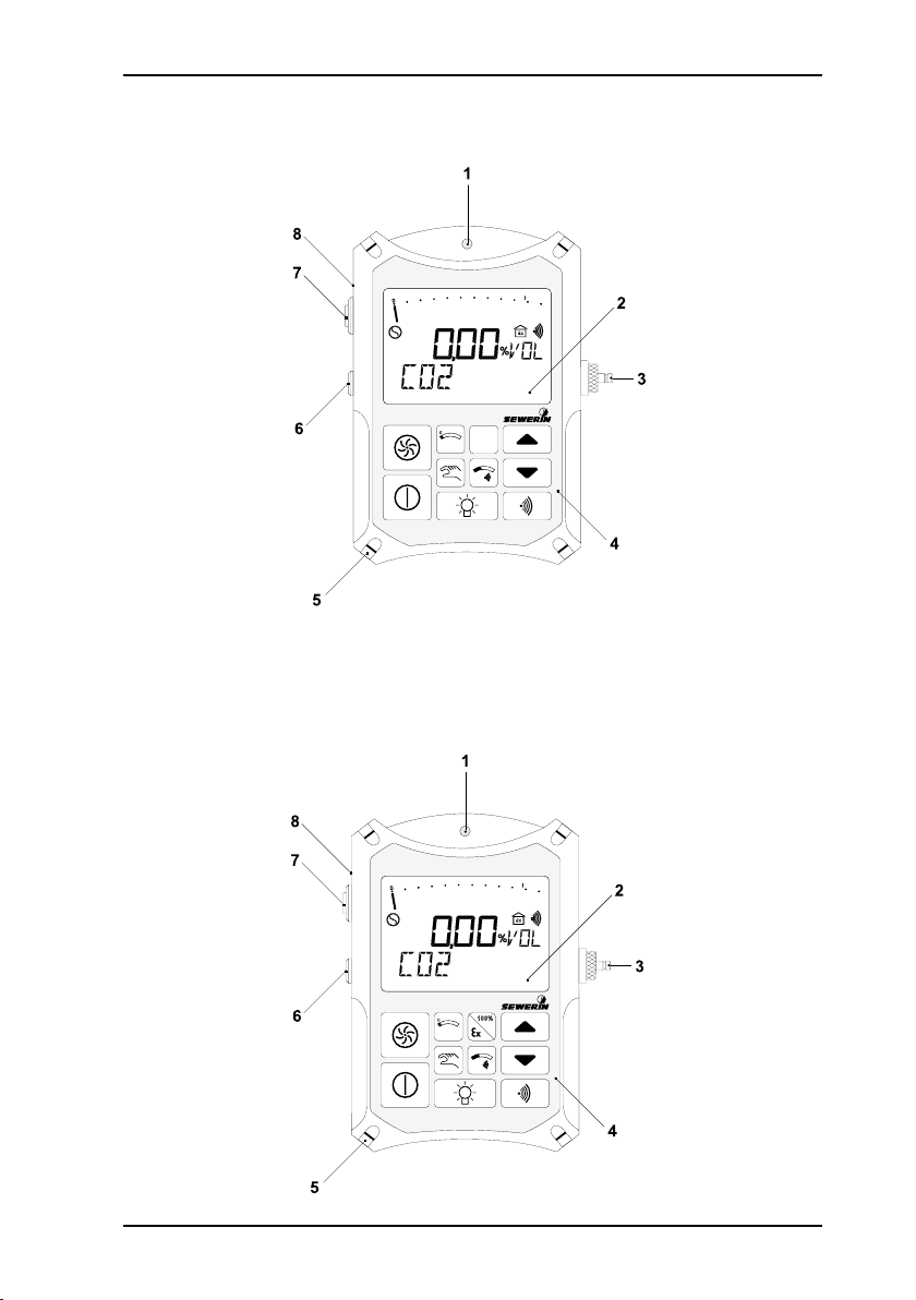
Illustration EX-TEC Combi
EX-TEC® Combi
EX-TEC® Combi
100%
Device variation 1
Device variation 2
Page 4
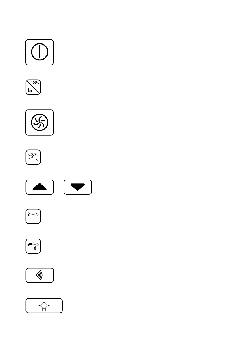
Brief operating instructions
EX-TEC Combi: brief operating instructions
Switch on/off
Toggle between GAS WARNING/GAS
MEASUR E M ENT op e rat i n g mo d es
(Device variation 2)
Device variation 1: Toggle between
GA S WAR NING/GAS MEASURE MENT operating modes
Switch pump on/off
(in GAS MEASUREMENT mode)
Toggle between automatic/manual gas
switching
Change the gas displayed (in manual
operation)
Zero-point correction for the gas displayed
Display gas alarm thresholds AL1 and
AL2
Acoustic clearance of the AL1 alarm
Switch LCD illumination on/off (switches
off automatically after about 4
Page 5

Operating Instructions
EX-TEC® Combi
15.06.2005 – V2.X – 103401 – en
Page 6

For your safety
This product may only be operated by appropriately-trained persons who
are familiar with the relevant operating manual.
It may only be used for its designated purpose, i.e. for industrial and commercial use.
Repair work may only be carried out by specialists or by persons who have
undergone appropriate training.
Any alterations or modifications to the product require the prior approval of
Hermann Sewerin GmbH. In the event of unauthorised alterations to the
product the manufacturer accepts no liability for damage.
Only Hermann Sewerin GmbH accessories may be used with the product.
Only spare parts approved by us may be used for repairs.
Hermann Sewerin GmbH accepts no liability for damage resulting from
non-compliance with the foregoing. The guarantee and liability provisions
in the Hermann Sewerin GmbH terms of sale and supply are not extended
by the foregoing.
We reserve the right to make changes in the context of continued technical development.
In addition to these instructions, please comply with generally applicable
safety and accident-prevention regulations!
Symbols used:
(⊗)
CAUTION!
This symbol warns of dangers that may threaten
the safety of the user or maty damage or destroy
the product.
Note:
This symbol flags information and hints extending
beyond the actual operation of the product .
This symbol will hereinafter identify all operating
modes and measuring techniques not tested by
DMT!
Page 7

Contents Page
1 EX-TEC Combi system ...........................................................1
1.1 Excess-gas warning and measuring instrument .......................1
1.2 Fields of application ..................................................................2
1.3 Test certificates .........................................................................4
1.4 Carrying equipment ...................................................................5
2 Safety .......................................................................................6
2.1 Safety notes .............................................................................. 6
3 Measuring operation ...............................................................8
3.1 Instrument description ...............................................................8
3.2 Switching on ..............................................................................9
3.3 Modes .....................................................................................13
3.4 Switching gases ...................................................................... 15
3.5 Alarms .....................................................................................16
3.6 Instantaneous value alarms (AL1, AL2, AL3) ..........................17
3.7 Short-term value alarm (KZW), long-term value alarm (LZW),
minimum and maximum values (MIN/MAX) ............................23
3.8 Zero point adjustment .............................................................26
3.9 Illumination and contrast ......................................................... 26
3.10 Operating hours display and battery alarm ............................. 27
3.11 Switching off ............................................................................28
4 Charging ................................................................................29
4.1 Charging and charge maintenance .........................................29
4.2 Self-discharge ......................................................................... 30
5 Testing/maintenance .............................................................31
5.1 Function testing, testing display accuracy, maintenance ........32
5.2 Test set ....................................................................................34
5.3 Test gases ...............................................................................35
5.4 Testing the pump power, zero point and sensitivity .................37
I
Page 8

Contents Page
6 Info menu ...............................................................................39
6.1 Menu structure ........................................................................ 39
6.2 Overview ................................................................................. 40
7 Adjustment menu ..................................................................43
7.1 Menu structure ........................................................................ 43
7.2 Setting the H2S sensor ............................................................44
7.3 Setting the CO sensor .............................................................45
7.4 Setting the O2 sensor ..............................................................46
7.5 Setting the CO2 sensor ............................................................47
7.6 Setting the CH4 sensor ............................................................48
7.7 Setting the measurement quantity ..........................................50
7.8 Setting the test gas concentration ...........................................51
7.9 Inspection confirmation ........................................................... 54
7.10 Leaving the adjustment menu .................................................55
8 Memory menu ........................................................................56
8.1 Menu structure ........................................................................ 56
8.2 Clearing memory .....................................................................57
8.3 Setting the memory interval ....................................................58
8.4 Setting the memory mode .......................................................60
8.5 Setting the short-term value interval .......................................61
8.6 Leaving the memory menu ......................................................62
9 System menu .........................................................................63
9.1 Menu structure ........................................................................ 63
9.2 Setting the date/time ............................................................... 64
9.3 Setting the inspection interval ................................................. 66
9.4 Setting the inspection block ....................................................69
9.5 Setting the 100 vol.% range ....................................................70
9.6 Setting the PIN code ............................................................... 71
9.7 Setting the alarm thresholds ..................................................73
9.8 Checking the LCD ...................................................................77
9.9 Leaving the system menu ....................................................... 77
II
Page 9

Contents Page
10 Application hints ...................................................................78
10.1 Application hints from report of suitability examination
PFG-No. 41300401P ...............................................................78
11 Technical aspects ................................................................. 80
11.1 Technical notices ..................................................................... 80
11.2 Technical data .........................................................................82
11.3 Error messages .......................................................................93
11.4 Error and Alarm properties ......................................................97
11.5 Wearing Parts .........................................................................98
11.6 Spare parts ..............................................................................98
11.7 EC-Sensor Disposal ................................................................98
12 Hints on Disposal ..................................................................99
13 Delivery variants and accessories ....................................100
13.1 Delivery variants ....................................................................100
13.2 Accessories ...........................................................................101
Appendix ............................................................................................108
EC-type-examination certificates .........................................................108
Declaration of Conformity .................................................................... 118
Inspection protocols ............................................................................ 119
III
Page 10
1
1 EX-TEC Combi system
1 EX-TEC Combi system
1.1 Excess-gas warning and measuring instrument
The EX-TEC Combi is a combined warning and measuring
instrument for a number of different gases. It consists of:
the basic instrument, incorpora ting a pum p and a dat a
memory for documentation
purposes
4 sensor sockets for the measurement of up to 5 different
gases
The following sensors are available:
methane CH
4
or
propane C3H8
or nonane C9H20 (*)
carbon dioxide CO
2
oxygen O
2
hydrogen sulphide H2S
carbon monoxide CO
combined H2S/CO sensor
(*) This operating manual only describes methane mea-
surement!
Page 11

2
1 EX-TEC Combi system
1.2 Fields of application
The EX-TEC Combi is suitable for use in the following fields:
WARNING mode
Workplace (atmospheric) monitoring in shafts and chambers in
these fields:
drinking-water supply (metering
and transfer shafts)
district-heating systems
telecommunications shafts
effluent-treatment systems
(sewage works, pump sumps,
digestion-tank areas, rainoverflow basins)
traffic areas
accessible culverts
Warning of explosive*) mixtures
- due to leaking gas pipes near the shaft
- due to the proximity of oil, coal, natural-gas or LPG storage
facilities
- due to the proximity of landfill sites, marshland, chemical
works, filling stations or refineries
- due to cleaning or coating work with substances containing
solvents
- due to the prohibited introduction of combustible substances
into the canal network (e.g. petrol leaks)
*) the EC prototype test certificate DMT01ATEX G 002 includes measurement functions
of the LEL methane/propane range
Warning of an oxygen defect /oxygen excess
- due to an increase in other gas components
- due to the decomposition of organic waste in shafts (e.g. wet
leaves)
Page 12

1 EX-TEC Combi system
- due to welding and heating processes with naked flames
- due to air depletion
Warning of toxic gases
- due to the formation of carbon dioxide by bacterial conversion
processes
- due to the formation of carbon dioxide in areas where there
is mineral water
- due to the formation of carbon dioxide in exhaled air
- due to the formation of hydrogen sulphide in effluent
- due to the formation of carbon monoxide from incomplete
combustion (e.g. poorly-adjusted gas-heating systems)
- due to the formation of carbon monoxide near highways or
car-parks
GAS-MEASURING mode *)
Determining gas concentrations
Localisation
- measuring gas concentration in probe holes
- determining which probe
hole has the maximum concentration
Gas injection
- monitoring filling with natural
gas and oxygen extraction
- measuring the methane and
oxygen concentration
Inertisation
- monito r ing flus h ing with
nitrogen and natural-gas
extraction
- measuring the methane and
oxygen concentration
*) No measuring function for explosion protection in accordance with guideline 94/4/EG.
3
Page 13

4
1 EX-TEC Combi system
1.3 Test certificates
Passive explosion protection
The EX-TEC Combi has been tested for explosion protection in
accordance with the European norm (CENELEC):
EC prototype test certificate:
Identification: II 2 G EEx ib d IIB T3
Testing institution: Physikalisch-Technische Bundesan-
Active explosion protection (measuring function)
The EX-TEC Combi has also been undergone a measurementfunction test in gas-warning mode:
EG prototype test certificate:
Test report: PFG n° 41300401
Testing institution: Deutsche Montan-Technologie GmbH
PTB 96 ATEX 2166, supplements 1
and 3
stalt, Braunschweig
DMT 01 ATEX G002, supplement 1
(measurement range 0 – 100 %LEL
methane/propane)
measurement range 0 – 25 vol.%
oxygen, measurement of oxygen
defect and excess,
measurement range 0 – 5 vol.% of
carbon dioxide,
measurement range 0 – 500 ppm of
carbon monoxide
measurement range 0 – 100 ppm of
hydrogen sulphide
(DMT), Essen
The test certificates can be found in the appendix.
Page 14

front view side view back view
front view side view back view
1.4 Carrying equipment
TRIANGEL carrying system
a quick and easy way of carrying the instrument, consisting of a
carrying strap and neck-pad
1 EX-TEC Combi system
CROSS-STRAP carrying system
a comfortable way to carry the instrument for longer periods,
consisting of 2 carrying straps crossed at the back
5
Page 15
6
2 Safety
2 Safety
2.1 Safety notes
CAUTION!
Always use original SEWERIN accessories with the
EX-TEC Combi.
CAUTION!
Always use a probe hose with a hydrophobic filter.
CAUTION!
Do not use other than the original SEWERIN fine
dust filters with the EX-TEC Combi. Never use ac-
tivated carbon filters, as these will collect H2S gas
particles, thus causing the warning feature to stop
working properly.
CAUTION!
Observe the permissible operating temperature of
-10 °C to +40 °C.
CAUTION!
The EX-TEC Combi may only be recharged in an
area not exposed to the danger of explosion.
Page 16
2 Safety
CAUTION!
Use the test gases only in well-ventilated areas,
as some concentrations exceed the pertinent MAK
values.
CAUTION!
The EX-TEC Combi satisfies the limits of the EMV
regulation. When using it near mobile radio equipment please also observe the instructions in their
manuals.
7
Page 17

8
3 Measuring operation
3 Measuring operation
3.1 Instrument description
Note:
Fold out the illustration inside the front cover!
Item description function
1 alarm lamp optical warning on:
2 LCD display of:
3 probe connection connection for:
4 keypad instrument operation
5 attachment for carrying systems:
6 outlet for the gas sample
7 buzzer acoustic warning on:
8 interface serial RS-232-interface for con-
breaching alarm thresholds
display of error messages
gas concentrations
menu items
operating conditions
error messages
probe hose
test set
Triangel
cross-strap
breaching alarm thresholds
display of error messages
nection to a PC
(⊗)
Page 18
3.2 Switching on
3 Measuring operation
always switch the instrument
on in “fresh air”
press the on/off key for about
3 seconds
the optical and acoustic control
signals (items 1 and 7) operate
for about 3 seconds
the LCD illumination automati-
cally switches on for about 4
minutes
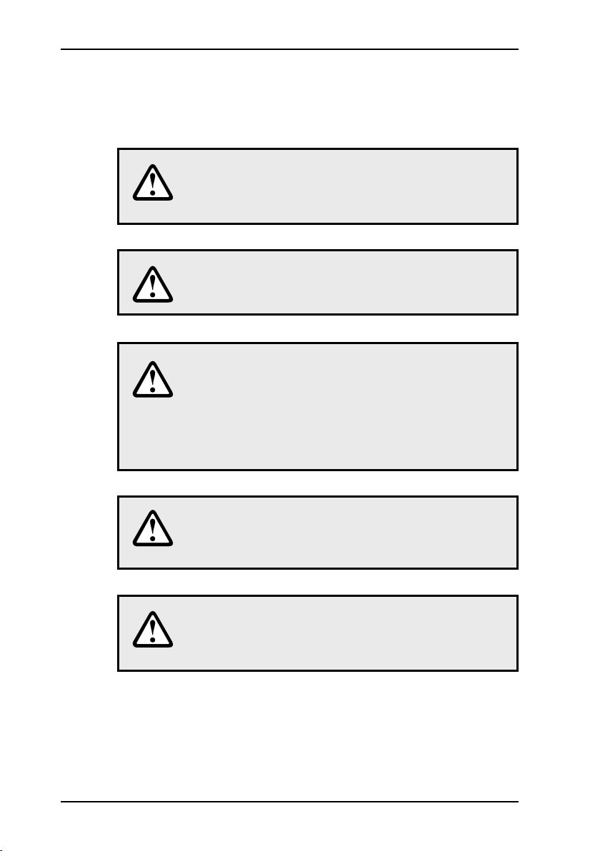
available operating hours are
displayed in the form of the
battery symbol and bars (e.g.:
5 hours = 5 bars)
the built-in pump runs at con-
stant power
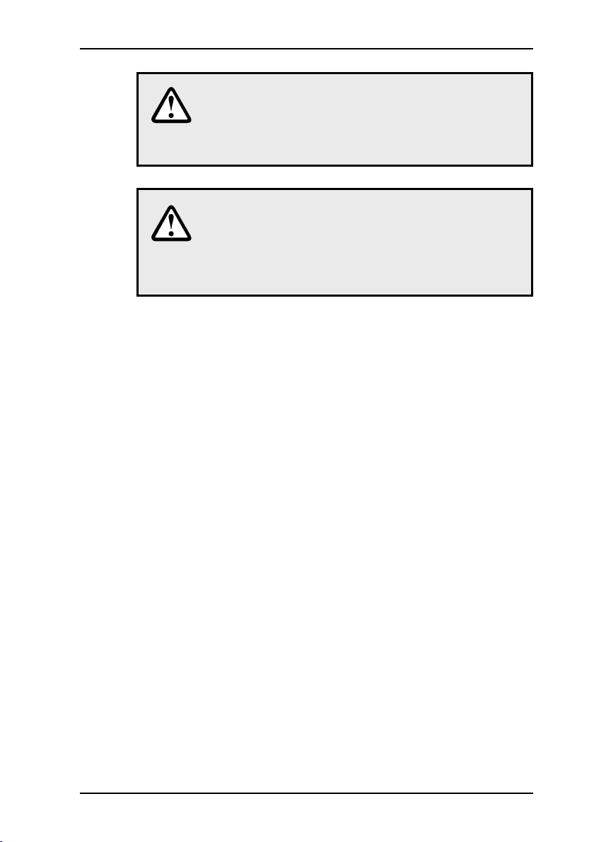
the software version number
(e.g. 2.1) and instrument type
(Combi) are displayed
Note:
All the following instrument displays assume that
the EX-TEC Combi is fully equipped for the measurement of 5 gases (CH4 - CO2 - O2 - H2S - CO).
9
Page 19
10
3 Measuring operation
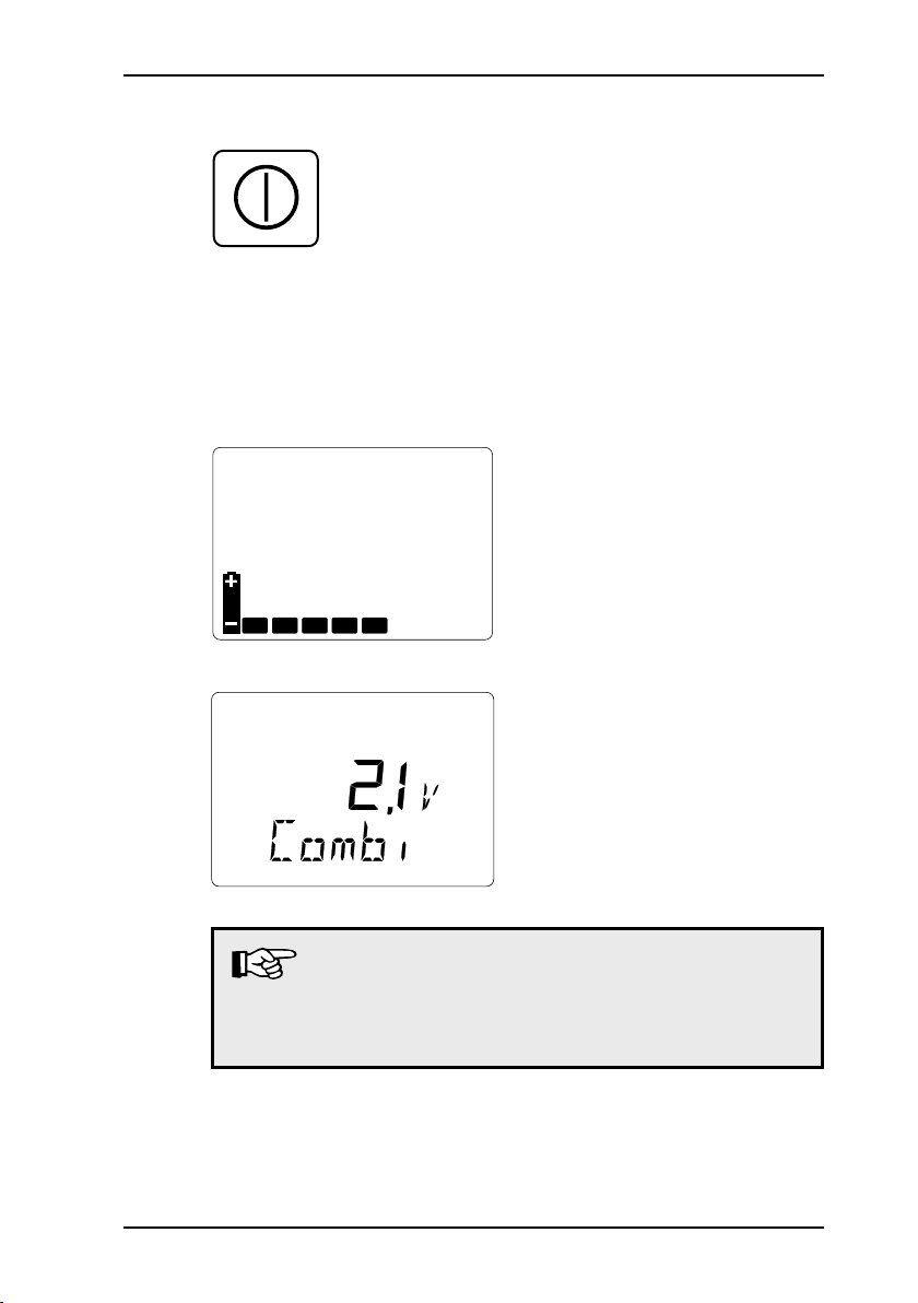
CH4 - methane
the measurement range for
methane is displayed:
0.00 – 4.40 %VOL
depending on your last setting
a display in the %UEG, %LEL,
%LIE, %VOL, %GAZ quanti-
ties may also be possible (cf.
section 7.6: Adjusting the CH4
sensor)
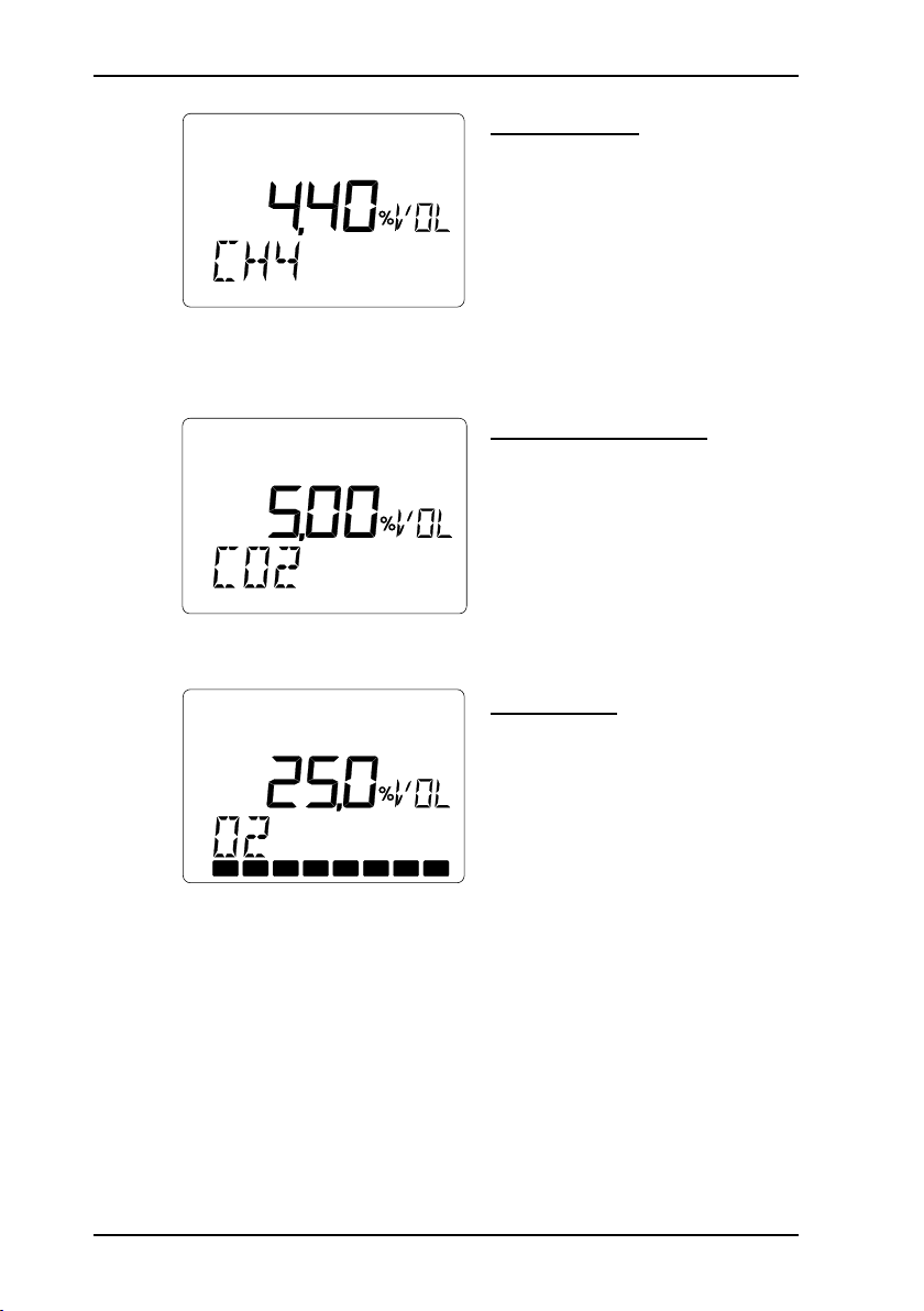
CO2 - carbon dioxide
the measurement range for
carbon dioxide is displayed:
0.00 – 5.00 %VOL
depending on your last setting
a display in the %VOL, %GAZ
quantities may be possible
(cf. section 7.7: Setting the
measurement quantity)
O2 - oxygen
the measurement range for
oxygen is displayed:
0.0 – 25.0 %VOL
depending on your last setting
a display in the %VOL, %GAZ
quantities may be possible
(cf. section 7.7: Setting the
measurement quantity)
display of the sensor lifetime
in the form of bars (cf. section
11.2: Technical data):
8 bars = 100 %
Page 20
3 Measuring operation
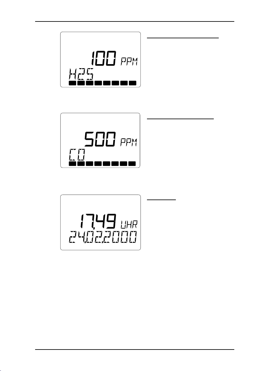
H2S - hydrogen sulphide
the measurement range for
hydrogen sulphide is displayed:
0 – 100 PPM
display of the sensor lifetime
in the form of bars (cf. section
11.2: Technical data):
8 bars = 100 %
CO - carbon monoxide
the measurement range for
carbon monoxide is displayed:
0 – 500 PPM
display of the sensor lifetime
in the form of bars (cf. section
11.2: Technical data):
8 bars = 100 %
Time/date
the current time (e.g.17:49)
and date (e.g. 24.02.2000) are
displayed
properly-set values are impor-
tant for the documentation of
your readings
you can correct any variances
(cf. section 9.2: Setting the
date/time)
11
Page 21
12
3 Measuring operation
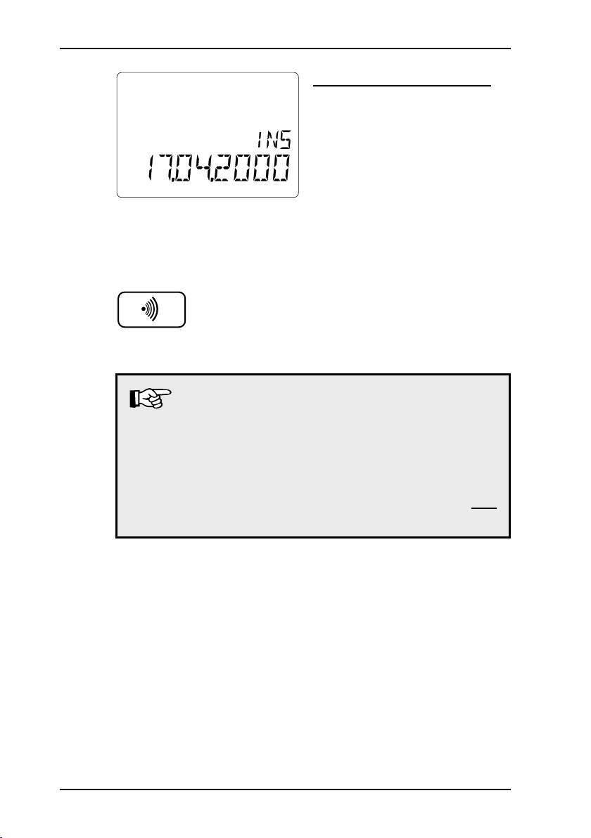
Next scheduled inspection
(display optional)
if you have set an inspection
interval, the next scheduled
inspection (e.g. 17.04.2000) is
displayed for about 3 seconds
(cf. section 9.3: Setting the
inspection interval)
depending on the date and
set schedule, the interval or
continuous alarm may also be
triggered (items 1 and 7)
clearing the alarm with the
buzzer key or waiting for 15
seconds switches to measuring
operation
Note:
If the EX-TEC Combi now automatically switches
off, the inspection date has passed with the inspection block switched on (cf. section 9.4: Setting the
inspection block).
The instrument does not revert to measuring operation until an inspection has been carried out and
confirmed.
Page 22
3.3 Modes
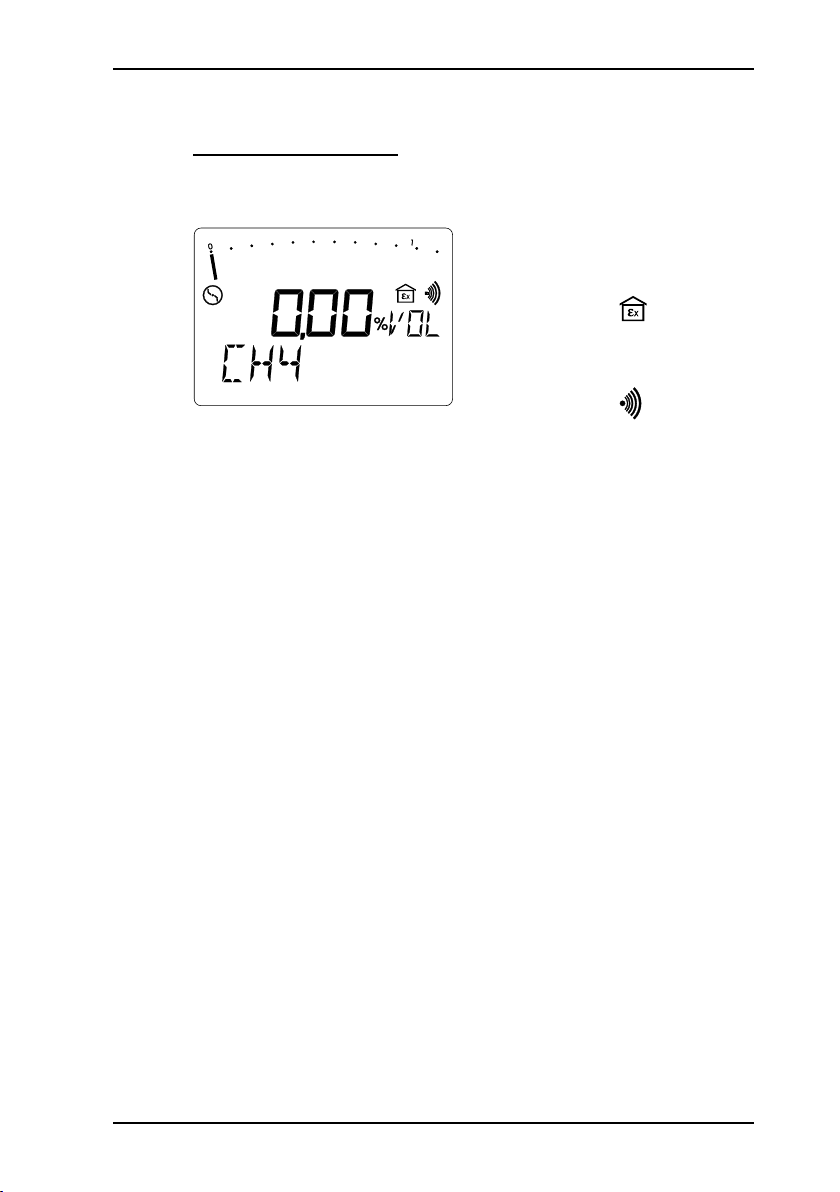
GAS-WARNING mode
Monitoring the atmosphere in shafts and chambers (cf. section 1.2: Fields of application)
CH4 - CO2 - O2 - H2S - CO
3 Measuring operation
im m edi at ely af t er bei ng
switched on the EX-TEC Combi
is always in warning mode
Indication:
all a la r m t hr es h ol ds ar e
activated
Indication:
each avail able gas is dis-
played for about 3 seconds
before switching to the next
Sequence:
Every 5 seconds an operating
signal is activated as a marker.
It is both, acoustic (item 7) and
optical (item 1). The optical
signal acts as a control that
the instrument is functioning
in gas-warning mode.
If the op e r a ting si g n al is
switched off, the monitoring
of the ga s conc e n t ra t i on
is no long er insur ed. The
endangered area must be left
immediately.
13
Page 23
14
3 Measuring operation
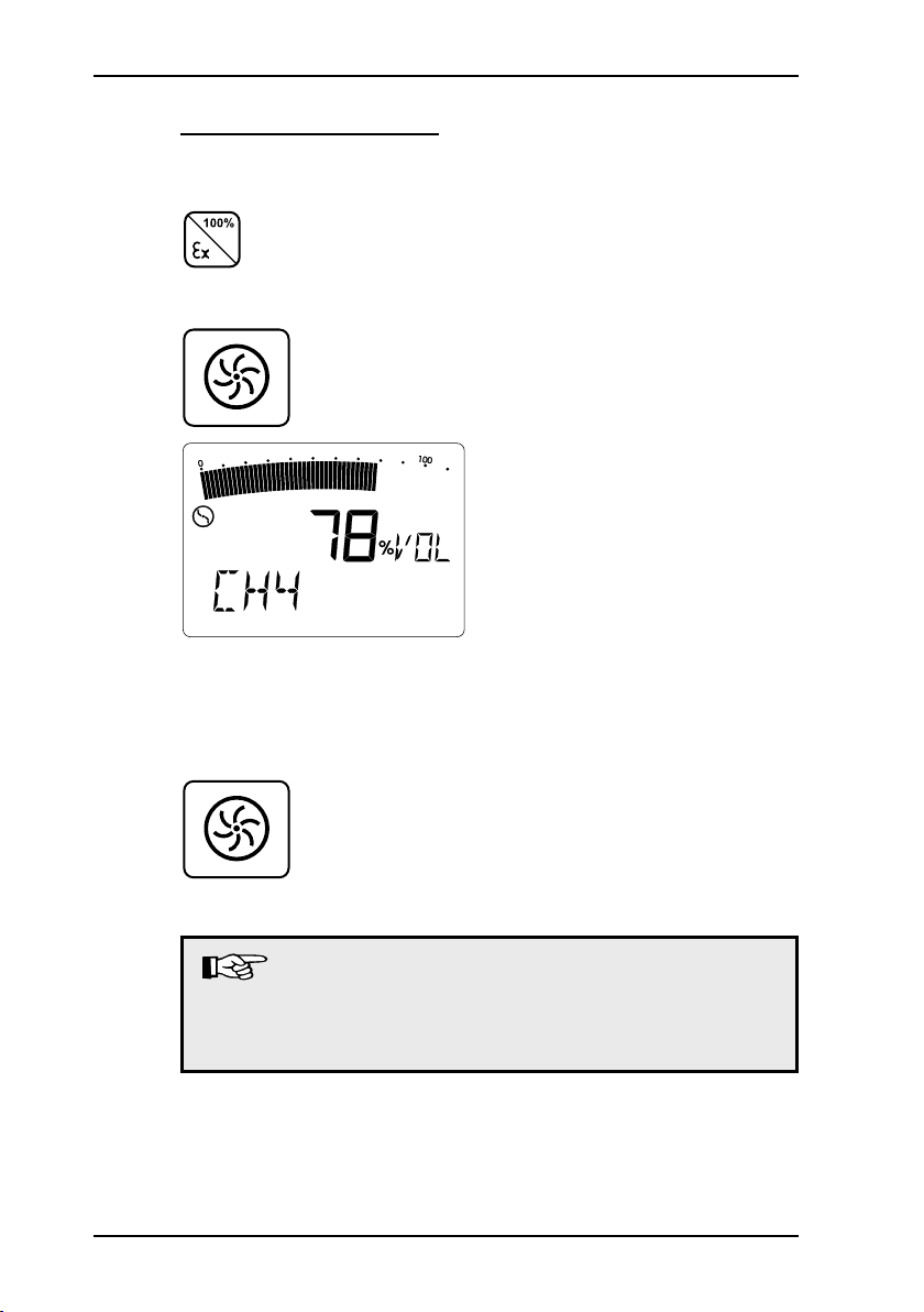
GAS-MEASURING mode (⊗)
Determining gas concentrations (cf. section 1.2: Fields of
application)
pressing the operating-mode
key (instruments variant 2)
for about 3 seconds switches
between the two modes
on instruments variant 1, the
switching is carried out by
pressing the pump-key for
about 3 seconds
in this mode all alarm thresholds
and the operating signal are
switched off
the pump now runs at maxi-
mum power
NB: (no symbols)
each avail able gas is dis-
played for about 3 seconds
before switching to the next
Sequence:
CH4 - CO2 - O2 - H2S - CO
in this mode, depending on
the task at hand, you can also
switch the instrument‘s pump
on and off by briefly pressing
the pump-key
Note:
If you wish to use the EX-TEC Combi purely as a warn-
ing device, you can deactivate GAS-MEASURING
mode (cf. section 9.5: Setting the 100 vol.% range)!
Page 24
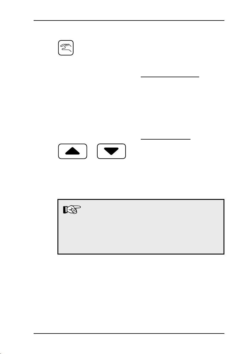
3.4 Switching gases
3 Measuring operation
repeatedly pressing the hand
key toggles between automatic and manual gas-type
switching
Automatic switching
each avail able gas is dis-
played for about 3 seconds
before switching to the next:
Sequence:
CH4 - CO2 - O2 - H2S - CO
Manual switching
each gas is displayed until a
arrow key is pressed
pressing a arrow key then
switches to the next gas:
Sequence (cursor up):
CH4 - CO2 - O2 - H2S - CO
Note:
In WARNING mode automatic switching always
has priority!
If the instrument is in manual switching mode and
no key has been pressed for about 10 seconds, it
shifts back to automatic switching!
15
Page 25

16
3 Measuring operation
3.5 Alarms
The „Technical Rules for Hazardous Substances (TRGS 402 and
900)“ require certain limit values to be monitored and adhered to
in the air in the workplace.
In WARNING mode only the EX-TEC Combi thus has three
different types of alarm: one optical (item 1), one acoustic (item
7) and one that takes the form of the LCD illumination (item 2)
switching on:
AL1, AL2, AL3 The instantaneous value alarm appears with
KZW The short-term value alarm appears with toxic
LZW The long-term value alarm appears with
all gases:
CH4 - CO2 - O2 - H2S - CO
when the measured gas concentration
exceeds or falls below a fixed threshold
value.
gases:
CO2 - H2S - CO
when the gas concentration averaged over an
adjustable time period (e.g. 15 minutes) has
exceeded an assessed limit value.
toxic gases:
CO2 - H2S - CO
when the gas concentration averaged over
an 8-hour working shift has exceeded a fixed
limit value.
Page 26
3 Measuring operation
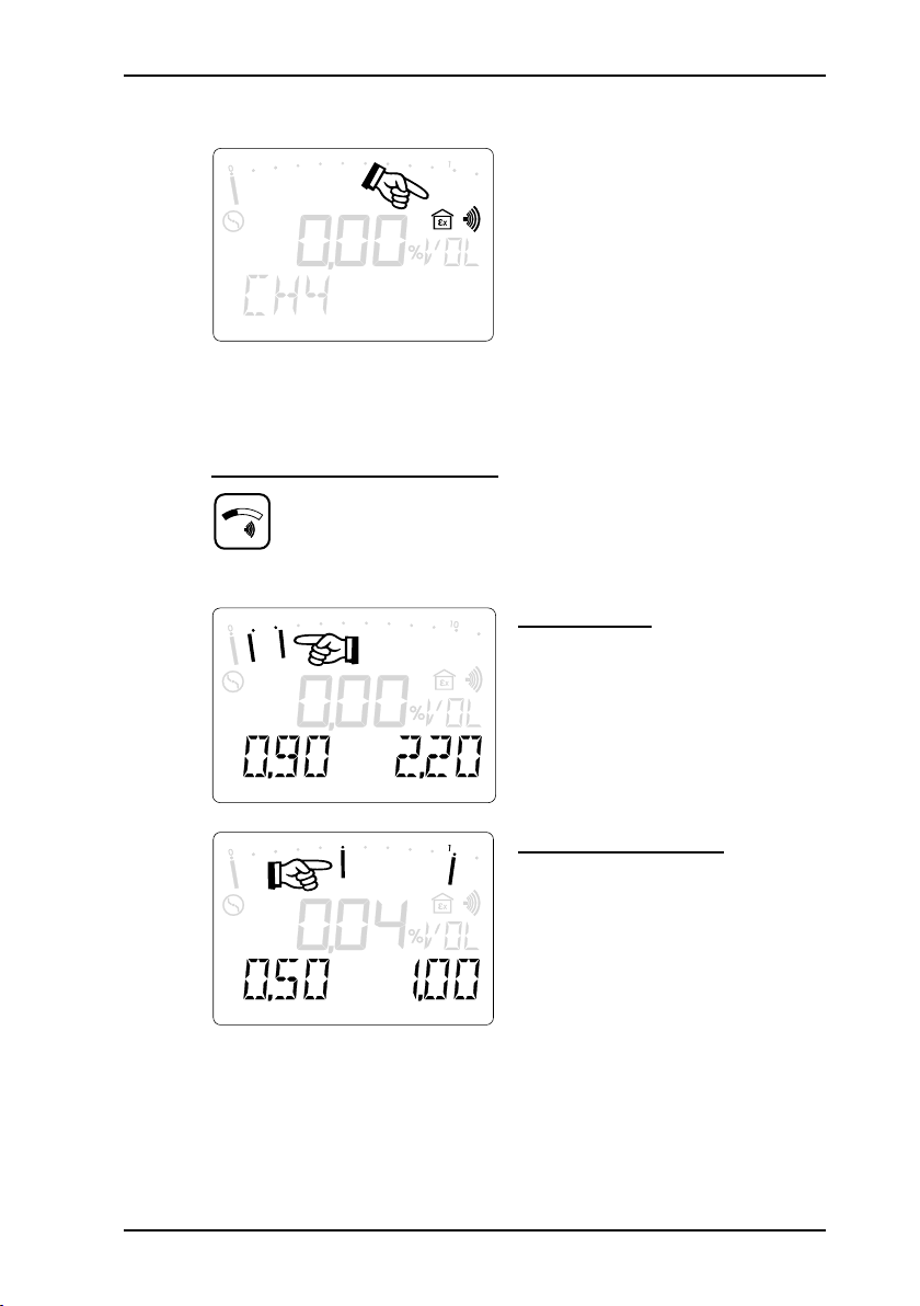
3.6 Instantaneous value alarms (AL1, AL2, AL3)
when in gas-warning mode
the EX-TEC Combi is constantly in alarm readiness
this is displayed in the LCD
by two symbols: Ex-area and
alarm threshold
the alarm is triggered as soon
as a threshold is breached
Display of alarm thresholds
holding down the threshold
value key displays the set
alarm thresholds for the pertinent gas
Methane CH
alarm thresholds (factory set-
4
tings):
AL1 = 0.90 %VOL = 20 %LEL
AL2 = 2.20 %VOL = 50 %LEL
Carbon dioxide CO
alarm thresholds (factory set-
4
tings):
AL1 = 0.50 %VOL (MAK value)
AL2 = 1.00 %VOL
17
Page 27
18
3 Measuring operation
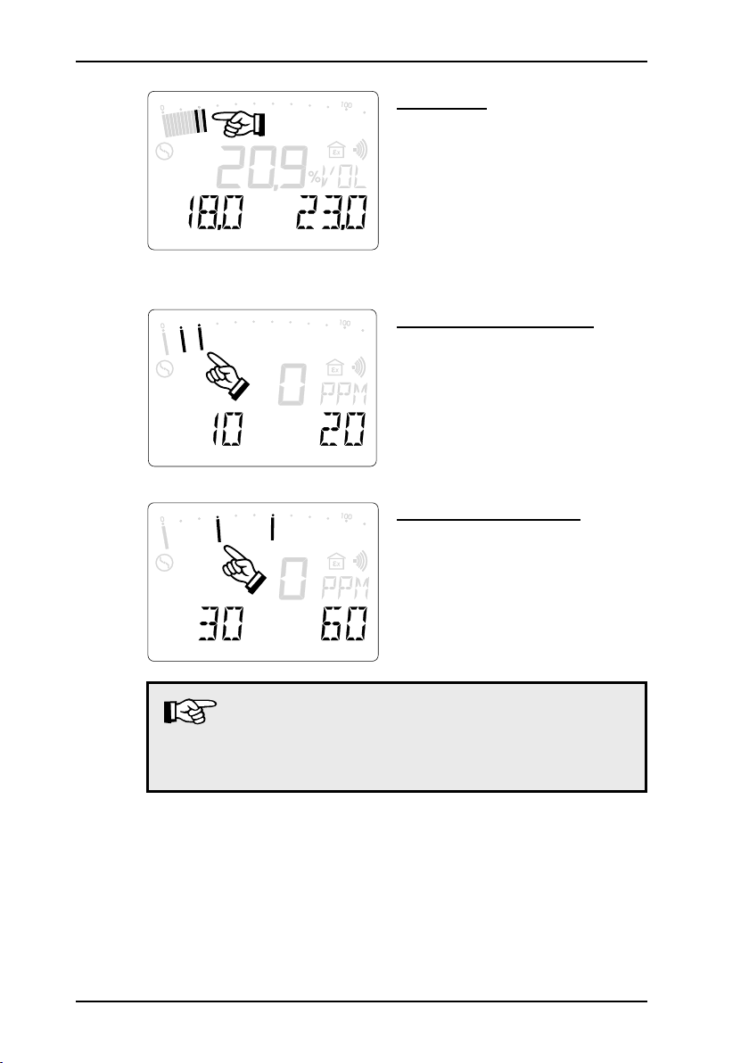
Oxygen O
alarm thresholds (factory set-
2
tings):
AL1 = 18.0 %VOL
AL2 = 23.0 %VOL
the AL1 alarm threshold is
triggered when the value falls
below the threshold
Hydrogen sulphide H2S
alarm thresholds (factory set-
tings):
AL1 = 10 PPM (MAK value)
AL2 = 20 PPM
Carbon monoxide CO
alarm thresholds (factory set-
tings):
AL1 = 30 PPM (MAK value)
AL2 = 60 PPM
Note:
You can alter the factory-set thresholds to your own
individual limits (cf. section 9.7: Setting the alarm
thresholds)!
Page 28
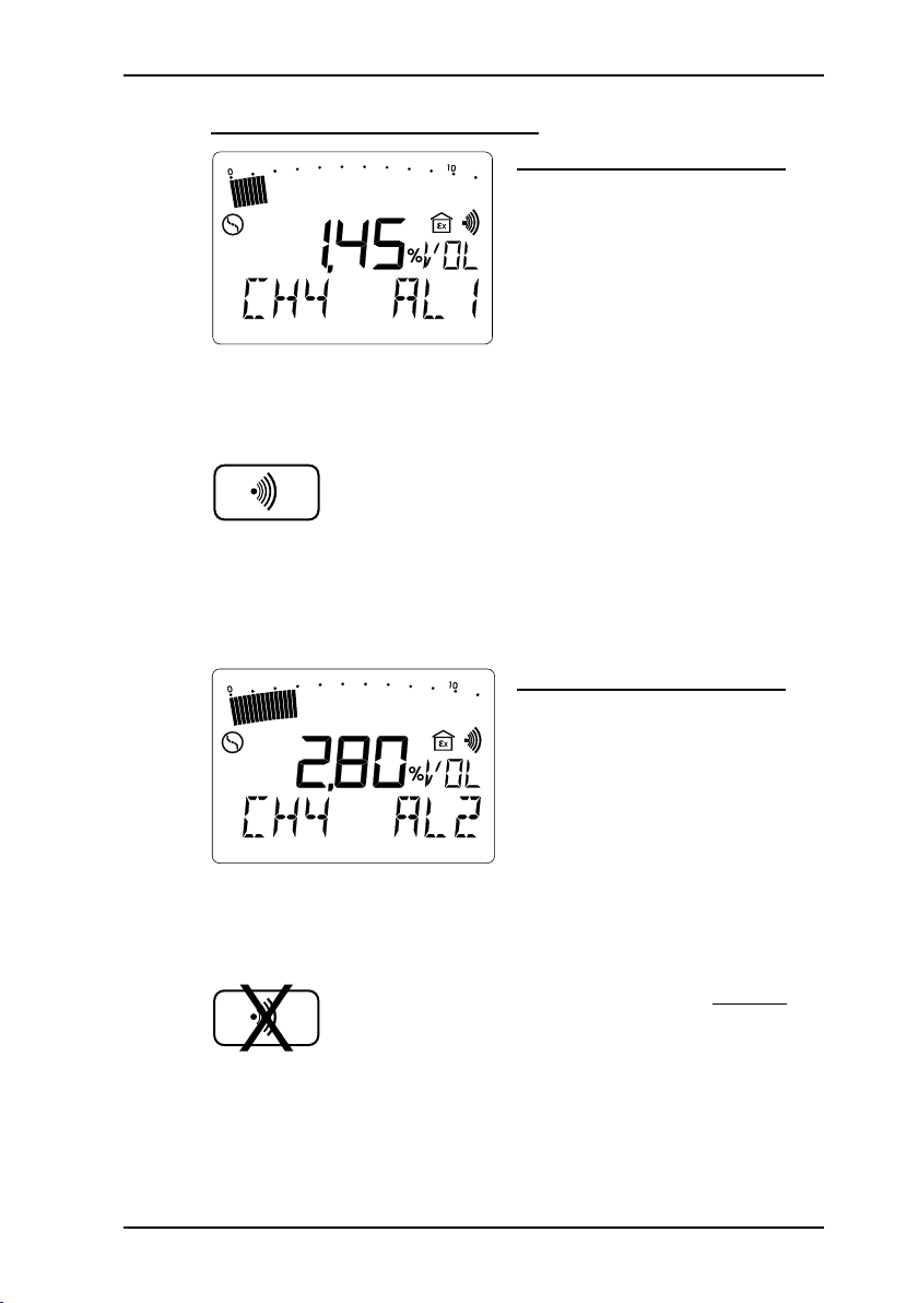
Triggering the alarm thresholds
AL1 alarm (Example: CH4)
AL2 alarm (Example: CH4)
3 Measuring operation
exceeding this alarm threshold
triggers:
- the optical alarm (item 1)
- the acoustic alarm (item 7)
- the appearance of AL1 in
the LCD
the interval tone is clearly dis-
tinguishable from the operating
signal
the AL1 alarm can be cleared,
th e optical ala rm (it em 1)
persists
if the concentration falls below
this alarm threshold, the optical and acoustic alarms (items
1 and 7) switch off
exceeding this alarm threshold
triggers:
- the optical alarm (item 1)
- the acoustic alarm (item 7)
- the appearance of AL2 in
the LCD
the continuous tone is clearly
distinguishable from the operating signal
the AL 2 alarm cannot be
cleared
if the concentration falls below this alarm threshold, the
alarm that sounds (AL1) can
be cleared
19
Page 29
20
3 Measuring operation
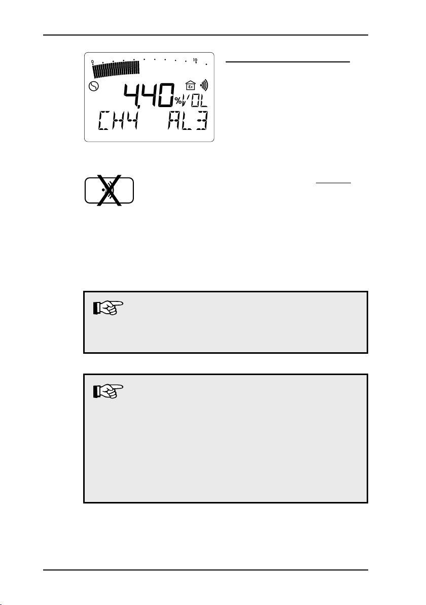
AL3 alarm (Example: CH4)
if the end of the measurement
range is exceeded, the optical
and acoustic alarms (items 1
and 7) are triggered and AL3
appears in the LCD
the continuous tone is clearly
distinguishable from the operating signal
the AL 3 alarm cannot be
cleared either
if the gas concetration falls be-
low the end of measurement
range, the AL3 alarm is reset
and the AL2 alarm activated
Note:
The AL3 alarm can be suppressed by switching
to GAS-MEASURING mode or switching off the
instrument!
Note:
In the GAS-WARNING mode, 0 – 100 %LEL methane
concetrations exceeding the upper measuring range
value can influence the accuracy of measurement.
After triggering the AL3 alarm in this measuring
range, the instrument must be inspected before any
further use (cf. section 5.1: Function testing, testing
display accuracy, maintenance). It is necessary to
repeat this operation the following days.
Page 30

3 Measuring operation
Note:
In the GAS-WARNING mode the following remarks
should be observed during operation at degrees below zero, high temperatures and high humidity:
Degrees below zero lead to a diminished display
(up to 4 % LEL at -10 °C) at the zero-point of the
methane and propane sensor. This can be compensated by a correspondingly lower adjustment
of the alarm thresholds.
When adjusting the methane sensor with dry gas,
high temperatures and high relative humidity (> 90 %)
could lead to a diminished display (up to 30 % of
measuring value). This can be compensated by
a correspondingly lower adjustment of the alarm
thresholds.
Note:
After triggering the AL3 alarm in the CO- or H2Smeasuring range, the instrument must be inspected
before any further use (cf. section 5.1: Function
testing, testing display accuracy, maintenance).
21
Page 31

22
3 Measuring operation
CH
C H
C H
4
3 8
9 20
Confirmation
CO
2
O *
2
H S
2
CO
End
of range
AL3
Main alarm
AL2
Pre-alarm
Al1
Alarm display
0.90 %VOL
20 %LEL
0.34 %VOL
2.20 %VOL
50 %LEL
0.86 %VOL
4,40 %VOL
100 %LEL
1.7 %VOL
0.50 %VOL 1.00 %VOL 5.00 %VOL
18.0 %VOL 23.0 %VOL 25.0 %VOL
10 PPM 20 PPM 100 PPM
30 PPM 60 PPM 500 PPM
X
X
NH
3
50 PPM 75 PPM 100 PPM
0.15 %VOL 0.35 %VOL 0.7 %VOL
Summary
All alarm thresholds (factory settings) and clearance facilities in
brief:
* Exception:
With oxygen O2 both thresholds take the form of a main alarm.
The AL1 alarm is triggered if the value falls below the threshold
of 18.0 vol.%.
Page 32

3 Measuring operation
3.7 Short-term value alarm (KZW), long-term value alarm (LZW), minimum and maximum values (MIN/MAX)
briefly press the on/off key in
gas-warning mode
MIN/MAX - minimum and maximum values
Often it is only the display of the minimum or maximum concentrations encountered so far that is of interest. These can be
displayed for all gases since the last time the instrument was
switched on.
MIN value (Example: CO2)
the minimum concentration
value (e.g. 0.25 %VOL) since
the last time the instrument
was switched on is displayed
MIN appears in the LCD
pressing the arrow-up key
brings you to the next display
MAX value (Example: CO2)
the maximum concentration
value (e.g. 0.75 %VOL) since
the last time the instrument
was switched on is displayed
MAX appears in the LCD
pressing the arrow-up key
brings you to the next display
23
Page 33

24
3 Measuring operation
KZW - short-term value alarm
This monitoring mode is based on an averaging period, usually 15 minutes (cf. section 8.5: Setting the short-term value
interval).
The total concentrations of the pertinent toxic gas over the averaging
period must not exceed the product of the MAK value and the
overshoot factor.
Gas MAK value Factor
carbon dioxide CO
hydrogen sulphide H2S 10 ppm 1
carbon monoxide CO 30 ppm 2
Example: a constant reading > 2.00 vol.% (= 4 x 0.50 vol.%) over
2
0.50 vol.% 4
15 minutes triggers the KZW alarm (main alarm),
which cannot be cleared.
KZW (Example: CO2)
the current short-term value
(e.g. 0.30 %VOL) since the
last time the instrument was
switched on is displayed
KZW appears in the LCD
pressing the arrow-up key
brings you to the next display
Page 34

3 Measuring operation
LZW - long-term value alarm
This monitoring mode is based on a shift length of 8 hours.
The total concentrations of the pertinent toxic gas over the length
of the shift must not exceed the MAK value.
Example: a constant reading > 0.50 vol.% over 8 hours trig-
gers the LZW alarm (main alarm), which cannot be
cleared
LZW (Example: CO2)
the current long-term value
(e.g. 0.10 %VOL) since the
last time the instrument was
switched on is displayed
LZW ap p ears in the LCD
(item 2)
the display of these values
disappears:
- if the on/off key is briefly
pressed
- if no key is pressed for about
10 seconds
Note:
Both alarms (KZW and LZW) can be suppressed
by switching to GAS-MEASURING mode or turning
the instrument off.
25
Page 35

26
3 Measuring operation
3.8 Zero point adjustment
if the EX-TEC Combi deviates
from its zero point after flushing with „fresh air“ (observe
tolerances), this can be corrected manually
pressing the zero point key
sets the zero point for the
gas displayed (max. 5% from
the end of the measurement
range)
if the zero point cannot be set,
the sensor must be adjusted
(cf. section 7: Adjustment
menu)
CO2 zero point
the zero point for carbon di-
oxide is 0.04 %VOL, as this
is the concentration found in
normal fresh air
3.9 Illumination and contrast
Illumination
repeatedly pressing the light
key switches the LCD illumination on and off
after about 4 minutes the illu-
mination automatically switches off again
Page 36

3 Measuring operation
Contrast
simultaneously pressing the
light key and a arrow key
increases or reduces the contrast of the LCD
your last setting is preserved
even when the instrument is
switched off
3.10 Operating hours display and battery alarm
Operating hours display
simultaneously pressing both
arrow keys during measuring
operation displays the number
of operating hours remaining
(e.g. 5 hours)
this display (battery symbol and
bars) disappears automatically
after about 10 seconds
Battery alarm
when the charge falls below
a threshold value the battery
symbol appears, the alarm
lamp flashes and an acoustic
signal sounds.
the battery alarm ca n be
cleared
when the battery symbol is
triggered, there is at least
another 15 minutes‘ operating
time remaining.
27
Page 37

28
3 Measuring operation
3.11 Switching off
this period of time is empha-
sized acoustically by a double
beep tone
after that the instrument must
be recharged (cf. section 4:
Charging)
press the on/off key for about
3 seconds
the optical and acoustic control
signals (items 1 and 7) operate
for about 3 seconds
remaining operating hours are
displayed in the form of the
battery symbol and bars (e.g.
5 hours = 5 bars)
Page 38

4 Charging
4.1 Charging and charge maintenance
Charging
When fully charged the instrument has a maximum of 9.5 hours‘
operating time with the pump running.
To charge the instrument you will need the docking station HS
1.2 A (see illustration), which can be used in the workshop or the
emergency vehicle.
The following connection sockets
can be found on the side of the
docking station HS 1.2 A:
AC/DC adapter M4 100 – 240 V~,
Car cable M4 12 V= mounting,
Car cable M4 12 V= mobile,
Car cable M4 24 V= mounting.
Switch the EX-TEC Combi off and place it in the charger. A display on the following lines appears:
the instrument still has 5 ope-
rating hours left (= 5 bars) and
will take another 3 hours to be
fully recharged
if it is fully charged, all the bars
appear and the numerical display disappears
4 Charging
Charge maintenance
As soon as the instrument is fully charged it automatically switches
to charge maintenance. It an be left in the charging adapter until
the next time it is needed.
29
Page 39

30
4 Charging
4.2 Self-discharge
If the instrument is not placed in the charging adapter when it is
switched off, this will cause the nickel-cadmium battery to selfdischarge, reducing the remaining operating time.
After a maximum of 30 days the instrument indicates no remaining
operating hours and it must be recharged.
Note:
Brief periods of use and protracted disuse may in
the long term lead to the co-called „memory effect“,
which means that the actual battery capacity available is less than what is shown in the display!
You can counteract this by fully discharging the
EX-TEC Combi regularly (e.g. once a month):
leave it switched on until it switches itself off, then
recharge it!
Page 40

5 Testing/maintenance
Note:
Gas warning instruments must always be tested by
the user before use or before each shift.
But at a minimum all 4 month. The test must
cover:
the battery charge
the display with environmental gas conditions
and test gases
(Technical bulletin BGI 518)
Note:
DIN EN 50073 and EN 45544-4 provides that portable gas warning instruments (of which the EX-TEC
Combi is one) must be tested as stipulated in their
operating instructions and immediately before use.
Items that the test is required to cover include the
zero point and display sensitivity with a field calibration instrument and test gas.
5 Testing / maintenance
Note:
In case of calibration data to multiple gas types are
stored, tests of display accuracy must be carried out
for all existing calibrations using corresponding test
gases (see section 5.3).
31
Page 41

32
5 Testing / maintenance
5.1 Function testing, testing display accuracy, maintenance
Please consider the necessary and prescribed instruments control according to:
EN 50073
EN 45544-4
BGI 518 (T023)
BGI 836 (T021)/Applicable only in Germany
DVGW worksheet G 465-4/Applicable only in Germany
Testing must also cover accessories used. Tests carried out and
other activities must be documented and the documentation retained for at least one year. The instrument tests required and
prescribed by DVGW G 465-4 (Technical Communications, reference) are divided into the following sections:
What ? Who ? When ?
function testing user prior to start working
testing display accuracy (adjustment)
servicing
(maintenance, any
repairs required)
specialist or specialist company
SEWERIN,
specialist or authorised company
daily to half-yearly
annual;
on defective instruments
Function testing
This is the simplest form of instrument test, which must be carried out by the user before starting work. It covers the following
items:
external condition including probe systems
function-testing the controls
battery charge
inspecting the pump and suction inlet
pump function
zero point
display of test gas feeding
Page 42

5 Testing / maintenance
Testing display accuracy (adjustment)
The frequency of the tests must be fixed depending on the sensors built-in and intensity of use.
The test must be carried out by a gas-supply company specialist,
a specialist company or by SEWERIN itself.
The test gas described (see section 5.3: Test gases) must be
used. The guidelines on the selection, installation, application
and maintenance of appliances for the detection and measuring
of flammable gases, oxygen or toxic gases (EN 50073 and
EN 45544-4) need to be observed
Moreover, national regulations BGI 518 and BGI 836 must be
complied with!
A full function test must also be carried out.
Servicing - maintenance and repair
Instruments must be serviced (and any necessary repairs carried out) at least once a year, by SEWERIN Service, a specialist
company authorised by SEWERIN or an authorised specialist of
the gas-supply company.
These activities must be documented in writing.
The test plaque on the instrument gives the date of the last
service and the scheduled date
of the next (e.g. 5/00 = May
2002).
Annual maintenance and repair must include at least the specialist care of the instrument, its settings and the replacement of
components with a limited lifetime.
Note:
Where instruments feature explosion protection
the applicable regulations must be observed!
Servicing operatives must be SEWERIN-
trained!
33
Page 43

34
5 Testing / maintenance
5.2 Test set
The test set SPE VOL is available to test the pump power, zero
point and sensitivity:
E
C
D
A
G
F
B
(Fig. 1)
Item description function
A device connection connection with:
probe connection
test heads
B test gas connection connection for:
test gas cans
pressure hose adapter
(in conjunction with pressure cylinder and pressure reducer)
C manometer Display of remaining pressure
inside the test gas container
D release button release of test gas
E fresh air supply opening for:
aspirating fresh air
fresh air hose
F needle valve with
flowmeter
reading the pump power in litres
per hour (l/h)
G connection hose connected to:
device
Page 44

5.3 Test gases
The following test gases are used in conjunction with the test set
SPE VOL tester to test zero point and sensitivity:
Gas Test gas
Methane CH
zero point: - fresh air
sensitivity 1:- 2.2 vol.% (50 %LEL) CH4 in synth. air
sensitivity 2: - 100 vol.% CH
Propane C3H
zero point:- fresh air
sensitivity- 1.0 vol.% (59 %LEL) propane (C3H8)
Nonane C9H
zero point:- fresh air
sensitivity- repla cement test gas 0.30 vol .%
Carbon dioxide CO
zero point:- fresh air
sensitivity- 2.0 vol.% (CO2) in synth. air
Oxygen O
zero point:- 100 vol.% methane (CH4)
sensitivity- fresh air
Hydrogen sulphide H2S
zero point:- fresh air
sensitivity- 40 ppm hydrogen sulphide (H2S) in
Carbon monoxide CO
zero point:- fresh air
sensitivity- 40 ppm carbon monoxide (CO) in
Ammonia NH
zero point:- fresh air
sensitivity- 50 ppm Ammonia (NH3) in Nitrogen
5 Testing / maintenance
4
4
8
in synth. air
(⊗)
20
propane (C3H8) in synth. air (reading to
be a returned when replacement test
gas: 0.35 vol.%)
2
2
synth. air
synth. air
(⊗)
3
35
Page 45

36
5 Testing / maintenance
These gases are supplied in 6 test gas cans:
2.2 vol.% CH4, 2.0 vol.% CO2, 17.5 vol.% O2, 40 ppm CO
1.0 vol.% C3H
0.3 vol.% C3H
40 ppm H2S
50 ppm NH
100 vol.% CH
8
8
3
4
Page 46

5 Testing / maintenance
5.4 Testing the pump power, zero point and sensitivity
Proceed as follows:
screw the selected test gas can onto the test set SPE VOL as
far as it will go (fig. 1, item B)
connect the instrument‘s probe connection (item 3) with the
hose of the test set SPE VOL (fig. 1, item A)
switch the instrument on; the pump aspirates fresh air through
the test set SPE VOL (fig. 1, item E)
enter your test results in the Inspection protocol
Pump power
use the needle valve (fig. 1, item F) to set the flow to maximum;
it must be greater than 30 l/h
Zero point
wait for the instrument to settle at a stable zero point; permis-
sible tolerances with fresh air are:
Gas
Methane CH
4
Tolerance
-0.15 – +0.15 vol.%
(-3 – +3 %LEL)
Propane C3H
8
-0.06 – +0.06 vol.%
(-3 – +3 %LEL)
Nonane C9H
20
(⊗)
-0.05 – +0.05 vol.% or
(-3 – +3 %LEL)
Carbon dioxide CO
2
+0.04 – +0.10 vol.%
Hydrogen sulphide H2S -3 – +3 ppm
Carbon monoxide CO -3 – +3 ppm
Ammonia NH
3
-3 – +3 ppm
(⊗)
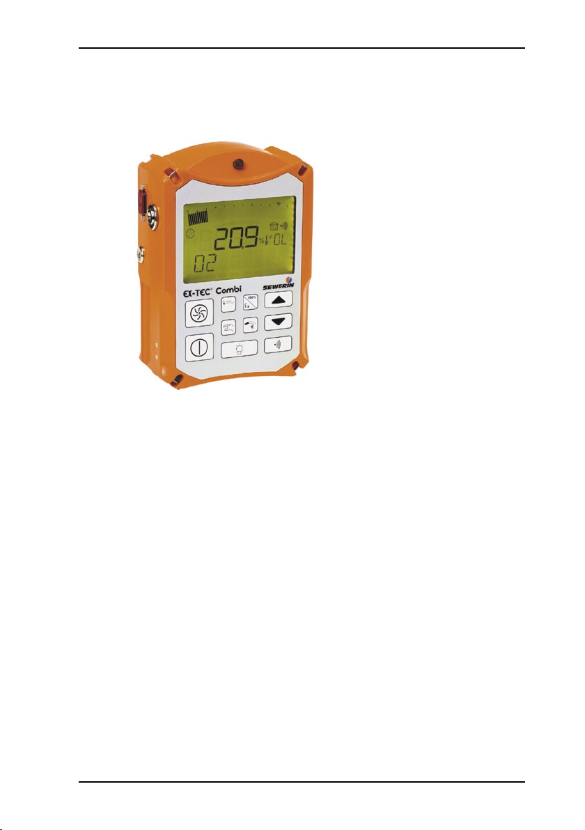
In a fresh air environment, the display of the oxygen sensor will
indicate a nominal value of 20.9 vol.%.
For zero calibration, the sensor is exposed to a pure CH4 environment (100 % by volume).
Tolerances:
Oxygen O2 -0.5 – +0.5 vol.%
37
Page 47

38
5 Testing / maintenance
If display values are outside these tolerances the pertinent sensor
must be readjusted (cf. section 7: Adjustment menu).
Sensitivity
press the release key (fig. 1, item D) on the test set SPE VOL
and adjust the flow to the fresh air value (fig. 1, item F)
hold down the release key until the displayed concentration
has settled at a stable value; permissible tolerances with test
gases:
Gas
Methane CH
Propane C3H
Nonane C9H
4
20
8
(⊗)
Carbon dioxide CO
2
Tolerance
2.0 – 2.4 vol.% (45 – 55 %LEL)
0.90 – 1.10 vol.% (54 – 64 %LEL)
0.35 – 0.40 vol.% (50 – 57 %LEL)
1.8 – 2.2 vol.%
Hydrogen sulphide H2S 37 – 43 ppm
Carbon monoxide CO 37 – 43 ppm
Ammonia NH
3
47 – 53 ppm
(⊗)
The oxygen sensor is tested for its sensitivity in a fresh air environment.
Tolerances:
Oxygen O2 20.4 – 21.4 vol.%
If display values are outside these tolerances the pertinent sensor
must be readjusted (cf. section 7: Adjustment menu).
Page 48

INFO V2.1
JUSTAGE
H2S 0 PPM
H2S 40 PPM
CO 0 PPM
CO 30 PPM
O2 0 VOL.%
O2 20,9 VOL.%
CO2 0 VOL.%
CO2 2,00 VOL.%
CH4 0 %UEG
CH4 50 %UEG
CH4 100 %VOL
CH4 %UEG %LEL %LIE %VOL %GAZ
%VOL %GAZ
PRÜFGAS
INS-OK
EXIT >
MEM-CLR
MEM-INT
MEM-STOP
KZW-INT
EXIT >
DAT/UHR
INS-INT
INS-STOP
100
%VOL
PIN-CODE
ALARM
LCD
EXIT
>
MEMORY
SYSTEM
EXIT
6 Info menu
6.1 Menu structure
6 Info menu
39
Page 49

40
6 Info menu
6.2 Overview
The info menu is accessible only when the EX-TEC Combi is
switched off.
now simultaneously press the
following 3 keys
you are now in the INFO menu
item (cf. menu structure)
the software version number
(e.g. V2.1) is displayed and
the LCD illumination automatically switches on for about 4
minutes
you must now enter your PIN
code (cf. section 9.6: Setting
the PIN code)
0001 = factory settings
only now do you have access
to all menu items
the pump runs at constant
power; it can be switched on
or off with the pump key at
any time
the arrow-up key returns you
to the menu structure
Page 50

6 Info menu
you are now in the ADJUST-
MENT menu item (cf. section
7: Adjustment menu)
the arrow-up key brings you
to the next display
you are now in the MEMORY
me n u item (cf. secti o n 8:
Memory menu)
the arrow-up key brings you
to the next display
you are now in the menu item
SYSTEM (cf. section 9: System menu)
the arrow-up key brings you
to the next display
41
Page 51

42
6 Info menu
... or
you are now in the EXIT menu
item
there are now 2 ways of con-
tinuing to navigate through the
menu structure
pressing the arrow-up key
returns you to the ADJUSTMENT menu item (cf. menu
structure)
briefly pressing the on/off key
leaves the menu structure and
the instrument switches to
measuring operation
Page 52

JUSTAGE
H2S 0 PPM
H2S 40 PPM
CO 0 PPM
CO 30 PPM
O2 0 VOL.%
O2 20,9 VOL.%
CO2 0 VOL.%
CO2 2,00 VOL.%
CH4 0 %UEG
CH4 50 %UEG
CH4 100 %VOL
CH4 %UEG %LEL %LIE %VOL %GAZ
%VOL %GAZ
PRÜFGAS
INS-OK
EXIT >
7 Adjustment menu
7.1 Menu structure
7 Adjustment menu
you are in the ADJUSTMENT
menu item
briefly pressing the on/off key
brings you to the adjustment
menu
43
Page 53

44
7 Adjustment menu
7.2 Setting the H2S sensor
H2S - zero point 0 PPM
release fresh air from the
SPE VOL
wait for the display to settle at
a stable value and confirm the
adjustment with the on/off key
(OK appears in the LCD)
pressing the arrow-up key
brings you to the next display
H2S - sensitivity 40 PPM
now release test gas 40 PPM
H2S from the SPE VOL (cf.
section 7.8: Setting the test
gas concentration)
wait for the display to settle at
a stable value and confirm the
adjustment with the on/off key
(OK appears in the LCD)
once this has happened, turn
off the test gas feed
pressing the arrow-up key
brings you to the CO-sensor
setting facility
Page 54

7.3 Setting the CO sensor
7 Adjustment menu
CO - zero point 0 PPM
now release fresh air from the
SPE VOL
wait for the display to settle at
a stable value and confirm the
adjustment with the on/off key
(OK appears in the LCD)
pressing the arrow-up key
brings you to the next display
CO - sensitivity 40 PPM
now release test gas 40 PPM
CO from the SPE VOL (cf. section 7.8: Setting the test gas
concentration)
wait for the display to settle at
a stable value and confirm the
adjustment with the on/off key
(OK appears in the LCD)
once this has happened, turn
off the test gas feed
pressing the arrow-up key
brings you to the O2-sensor
setting facility
45
Page 55

46
7 Adjustment menu
7.4 Setting the O2 sensor
O2 - zero point 0 %VOL
now release test gas 100 vol.%
CH4 from the SPE VOL
wait for the display to settle at
a stable value and confirm the
adjustment with the on/off key
(OK appears in the LCD)
once this has happened, turn
off the test gas feed
pressing the arrow-up key
brings you to the next display
O2 - sensitivity 20.9 %VOL
now release fresh air from
the SPE VOL (cf. section 7.8:
Setting the test gas concentration)
wait for the display to settle at
a stable value and confirm the
adjustment with the on/off key
(OK appears in the LCD)
pressing the arrow-up key
brings you to the CO2-sensor
setting facility
Page 56

7.5 Setting the CO2 sensor
7 Adjustment menu
CO2 - zero point 0 %VOL
now release fresh air from the
SPE VOL through a carbon
dioxide filter (Sewerin accessory, see section 13.2)
wait for the display to settle at
a stable value and confirm the
adjustment with the on/off key
(OK appears in the LCD)
pressing the arrow-up key
brings you to the next display
CO2 - sensitivity 2.00 %VOL
now release test gas 2.00
%VOL CO2 from the SPE VOL
(cf. section 7.8: Setting the test
gas concentration)
wait for the display to settle at
a stable value and confirm the
adjustment with the on/off key
(OK appears in the LCD)
once this has happened, turn
off the test gas feed
pressing the arrow-up key
brings you to the CH4-sensor
setting facility
47
Page 57

48
7 Adjustment menu
7.6 Setting the CH4 sensor
CH4 - zero point 0 %VOL
now release fresh air from the
SPE VOL
wait for the display to settle at
a stable value and confirm the
adjustment with the on/off key
(OK appears in the LCD)
pressing the arrow-up key
brings you to the next display
CH4 - sensitivity 2.20 %VOL
now release test gas 2.20 %VOL
(50 %UEG) CH4 from the SPE
VOL (cf. section 7.8: Setting
the test gas concentration)
wait for the display to settle at
a stable value and confirm the
adjustment with the on/off key
(OK appears in the LCD)
once this has happened, turn
off the test gas feed
pressing the arrow-up key
brings you to the next display
Page 58

7 Adjustment menu
CH4 - sensitivity 100 %VOL
now release test gas 100 %VOL
CH4 from the SPE VOL
alternatively you can dispense
with the SPE VOL and use
natural gas from the local
supply instead
wait for the display to settle at
a stable value and confirm the
adjustment with the on/off key
(OK appears in the LCD)
once this has happened, turn
off the test gas feed
Note:
Before switching to the next step, please wait until
the displayed concentration has reached the value
of 0 vol.%!
pressing the arrow-up key
brings you to the next display
CH4 - %UEG-range language
repeatedly pressing the on/off
key switches between the following displays in the %UEG
range:
%UEG - display in Untere Explosionsgrenze (D)
%LEL - display in Lower Explosive Limit (GB)
%LIE - display in Limite Inférieure d´Explosion (F)
%VOL - display in %VOL (D/GB)
%GAZ - display in %GAZ (F)
49
Page 59

50
7 Adjustment menu
conf i r m th e d i s pl a y, e. g .
%VOL, with the on/off key
(OK appears in the LCD)
this se t t in g is pre s er v e d
even when the instrument is
switched off
pressing the arrow-up key
brings you to the measurement-quantity setting facility
7.7 Setting the measurement quantity
CH4, CO2, O2 %VOL-range language
repeatedly pressing the on/off
key switches between the following displays in the vol.%
range:
%VOL - display in %VOL (D/GB)
%GAZ - display in %GAZ (F)
conf i r m th e d i s pl a y, e. g .
%VOL, with the on/off key
(OK appears in the LCD)
this se t t in g is pre s er v e d
even when the instrument is
switched off
pressing the arrow-up key
brings you to the test gas concentration setting facility
Page 60

CH4 GAS
CO2 GAS
O2 GAS
H2S GAS
CO GAS
EXIT >>
PRÜFGAS
7.8 Setting the test gas concentration
if you use use test gases
other than those supplied by
SEWERIN, the concentration
must be set accordingly
you are in the TEST GAS
menu item
7 Adjustment menu
briefly pressing the on/off
key brings you to the test gas
menu
Example: CH
you are now in the CH4 GAS
menu item
4
51
Page 61

52
7 Adjustment menu
briefly pressing the on/off key
brings you to the CH4 test gas
concentration setting facility
the current concentration is
displayed (e.g.: 50 %UEG =
2.20 %VOL)
you can set the desired con-
cen t r at i on by re p ea t ed ly
pressing or holding down a
arrow key
the selected concentration is
displayed (e.g.: 45 %UEG =
2.00 %VOL)
confirm the concentration with
the on/off key
this se t t in g is pre s er v e d
even when the instrument is
switched off
the adjustment ranges of the
individual test gas concentrations are:
Page 62

7 Adjustment menu
test gas 2.20 vol.% (50%LEL) methane CH
adjustment range:- 1.75 – 3.50 vol.% (40 – 80 %LEL)
step size- 0.05 vol.% (1 %LEL)
test gas 1.0 vol.% (59 %LEL) propane C3H
adjustment range- 0.68 – 1.36 vol.% (40 – 88 %LEL)
step size- 0.02 vol.% (1 %LEL)
test gas
for nonane C9H
20
(⊗)
replacement test gas 0.3 vol.%
propane (C3H8)
adjustment range- 0.30 – 0.50 vol.% (40 – 80 %LEL)
step size- 0.05 vol.% (1 %LEL)
test gas 2.00 vol.% carbon dioxide CO
2
adjustment range- 0.90 – 4.10 vol.%
tep size- 0.02 vol.%
test gas 20.9 vol.% oxygen O
2
adjustment range- 17.0 – 22.0 vol.%
tep size- 0.1 vol.%
test gas 40 ppm hydrogen sulphide H2S
adjustment range- 10 – 100 ppm
step size- 1 ppm
test gas 40 ppm carbon monoxide CO
adjustment range- 10 – 150 ppm
step size- 1 ppm
test gas
50 ppm Ammoniak NH
(⊗)
3
adjustment range- 10 – 100 ppm
step size- 1 ppm
4
8
repeatedly pressing a arrow
key brings you to the exit from
the test gas menu
53
Page 63

54
7 Adjustment menu
7.9 Inspection confirmation
EXIT >>
signpost (>>) to menu level 2
pressing the on/off key leaves
the test gas menu
pressing the arrow-up key
brings you to the inspection
INSPECTION OK
the EX-TEC Combi can re-
mind you of scheduled inspection and adjustment dates
this requires the inspection
interval and the inspection
block to be set in the system
menu (cf. sections 9.3 „Setting the inspection interval“
and 9.4 „Setting the inspection
block“)
confirm the inspection or ad-
justment you have carried
out with the on/off key (OK
appears in the LCD):
this date is stored as a function
of the set date (cf. section 9.2
„Setting the date/time“)
Page 64

7.10 Leaving the adjustment menu
7 Adjustment menu
the next inspection or adjust-
ment date is calculated in accordance with the set inspection interval
pressing the arrow-up key
brings you to the exit from the
adjustment menu
EXIT >
signpost (>) to menu level 1
pressing the on/off key leaves
the adjustment menu
you are now back at the top
ma i n -menu level an d can
switch between the following
menu items:
- JUSTAGE
- MEMORY
- SYSTEM
- EXIT
55
Page 65

56
8 Memory menu
MEM-CLR
MEM-INT
MEM-STOP
KZW-INT
EXIT >
MEMORY
8 Memory menu
8.1 Menu structure
the EX-TEC Combi continu-
ously stores readings from the
sensors that are present
these can later be read out
with the appropriate evaluation software (separate user
manual) via the RS-232-interface (item 8)
you are in the MEMORY menu
item
briefly pressing the on/off
key brings you to the memory
menu
Page 66

8 Memory menu
8.2 Clearing memory
(⊗)
MEMORY CLEAR
if you have set the memory
mode = stack memory (cf.
section 8.4: Setting memory
mode), this function enables
you to clear the entire readings
memory
confirm the clearance with
the on/off key (OK appears
in the LCD)
pressing the arrow-up key
brings you to the memory-interval setting facility
57
Page 67

58
8 Memory menu
8.3 Setting the memory interval
(⊗)
MEMORY INTERVAL
briefly pressing the on/off key
brings you to the memory-interval setting facility
by repe atedly pres sing or
holding down a arrow key
you can select the following
memory intervals:
Seconds range:
- 1 second
- 10 seconds
- 20 seconds
- 30 seconds
Minutes range:
- 1 minute
- 2 minutes
- 3 minutes
- 5 minutes
- 10 minutes
- 20 minutes
- 30 minutes
Page 68

8 Memory menu
Data-memory capacity
the EX-TEC Combi stores the following values in its data
memory:
- readings for each gas (instantaneous values at the moment
of scanning)
- event values for each gas (MIN, MAX, KZW, LZW values and
alarm overshoots)
- special error displays, alarms
depending on the set memory interval and the number of gases,
data memory can continuously record the following periods
(times in hh:mm):
M e m o r y
3 gases 4 gases 5 gases
interval
1 sec 01:02 00:41 00:29
10 sec 10:28 06:58 04:51
20 sec 20:56 13:56 09:43
30 sec 31:25 20:54 14:35
1 min 62:50 41:48 29:11
2 min 125:40 83:37 58:23
3 min 188:30 125:25 87:34
5 min 314:10 209:02 145:58
10 min 628:20 418:05 291:56
20 min 1256:40 836:10 583:52
30 min 1885:00 1254:15 875:48
Example: when the instrument is set to warn for 4 gases and with
the memory interval set to 1 minute you can record
event values over a period of 41 hours 48 minutes.
59
Page 69

60
8 Memory menu
confirm the interval with the
on/off key
this se t t in g is pre s er v e d
even when the instrument is
switched off
pressing the arrow-up key
brings you to the memorymode setting facility
8.4 Setting the memory mode
(⊗)
MEMORY STOP
you have the possibility to
choose the memory mode
between the ring memory or
the stack memory
briefly pressing the on/off key
brings you to the memorymode setting facility
by repeatedly pr e s s i ng a
arrow key you can select the
following memory modes:
OFF (ring memory)
readings are continuously written
to memory; when memory is
full the oldest values are overwritten
Page 70

ON (stack memory)
readings ar e only written to
memory until it is full, thus writeprotecting the oldest values
confirm the memory mode with
the on/off key
this se t t in g is pre s er v e d
even when the instrument is
switched off
pressing the arrow-up key
brings you to the short-term
value-interval setting facility
8.5 Setting the short-term value interval
SHORT-TERM VALUE INTERVAL
for the meaning of the KZW
alarm (cf. section 3.7 Shortterm value alarm (KZW), longterm value alarm (LZW), minimum and maximum values
MIN / MAX)
8 Memory menu
briefly pressing the on/off key
brings you to the short-term
value-interval setting facility
by repeatedly pressing or hold-
ing down a arrow key you can
select the following short-term
value-interval settings:
Adjustment range:
- 1 – 30 minutes
- 1 minute step size
61
Page 71

62
8 Memory menu
8.6 Leaving the memory menu
the usual setting is for a 15
minutes averaging interval
confirm the interval with the
on/off key
this se t t in g is pre s er v e d
even when the instrument is
switched off
pressing the arrow-up key
brings you to the exit from the
memory menu
EXIT >
signpost (>) to menu level 1
pressing the on/off key leaves
the memory menu
you are now back at the top
ma i n -menu level an d can
switch between the following
menu items:
- JUSTAGE
- MEMORY
- SYSTEM
- EXIT
Page 72

DAT/UHR
INS-INT
INS-STOP
100 %VOL
PIN-CODE
ALARM
LCD
EXIT
>
SYSTEM
9 System menu
9.1 Menu structure
9 System menu
you are in the SYSTEM menu
item
briefly pressing the on/off
key brings you to the system
menu
63
Page 73

64
9 System menu
9.2 Setting the date/time
DATE/TIME
briefly pressing the on/off key
brings you to the date/time
setting
Date
the last day (24 - flashing)
and month (02) to be set are
displayed
by repe atedly pres sing or
holding down a arrow key ...
... and confirming with the
on/off key you can first set the
day and then the month to the
current date
Year
the last year (2000 - flashing)
to be set is displayed
Page 74

9 System menu
by repe atedly pres sing or
holding down a arrow key ...
... and confirming with the
on/off key you can set the
current year
Time
the last hours (17 - flashing)
and minutes (49) to be set are
displayed
by repe atedly pres sing or
holding down a arrow key ...
... and confirming with the
on/off key you can first set the
hours and then the minutes to
the current time
these settings are preserved
even when the instrument is
switched off
pressing the arrow-up key
brings you to the inspectioninterval setting facility
65
Page 75

66
9 System menu
9.3 Setting the inspection interval
INSPECTION INTERVAL
the EX-TEC Combi can re-
mind you of regular scheduled
tests (e.g. inspections, adjustments)
this reminder is based on the
inspection interval
briefly pressing the on/off key
brings you to the inspectioninterval setting facility
Inspection interval = 0 – 52 CW
the last interval to be set is
displayed in CW (calendar
weeks), e.g.:
- 0 CW = function inactive
- 4 CW = monthly
- 52 CW = annual
by repe atedly pres sing or
holding down a arrow key ...
... and confirming with the
on/off key you can set the
desired interval
this se t t in g is pre s er v e d
even when the instrument is
switched off
pressing the arrow-up key
brings you to the inspectionblock setting facility
Page 76

9 System menu
Example: inspection interval
selected inspection interval:
04 weeks
inspection routine started
(i.e. inspection confirmed, see section 7.9):
10.02.2004
from these settings follows:
the next inspection has to be effected
between 09. – 15.03.2004
During the next 3 weeks the EX-TEC Combi will display the following references to the inspection date:
24.02.2004 – 01.03.2004 (> 1 week before)
LCD: the coming inspection date is
displayed for about 3 seconds
on switch-on
lamp/buzzer: inactive
instrument: the instrument then automati-
ca lly swit ches to meas uring
operation
02.03.2004 – 08.03.2004 (1 week before)
LCD: the coming inspection date is
displayed for about 3 seconds
on switch-on
lamp/buzzer interval lamps / interval tone
instrument: the instrument then automati-
ca lly swit ches to meas uring
operation
67
Page 77

68
9 System menu
09.03.2004 – 15.03.2004 (scheduled)
LCD: the due inspection date is dis-
lamp/buzzer: interval light/sound
instrument: when the display is cleared with
16.03.2004 – ... (from 1 week later)
LCD: the overdue inspection date is
lamp/buzzer: interval light/sound
instrument: depending on the setting of the
played on switch-on
the buzzer key (item 4) or after
waiting for about 15 seconds the
instrument automatically switches
to measuring operation.
displayed on switch-on
INS-STOP function (cf. section
9.4: Setting the inspection block)
the following conditions are possible:
INS-STOP = OFF
when the display is cleared with
the buzzer key (item 4) or after
waiting for about 15 seconds the
instrument automatically switches
to measuring operation
INS-STOP = ON
when any key is pressed (item
4) or after waiting for about 15
seconds the instrument automatically switches off.
Page 78

9.4 Setting the inspection block
9 System menu
INSPECTION STOP
to make sure your EX-TEC
Combi is regularly checked
you can activate an inspection block
this block does not become
active until the next inspection
date has passed (cf. section
9.3: Setting the inspection
interval)
after that you cannot use the
instrument until the inspection
has been carried out and
confirmed (cf. section 7.9:
Inspection confirmation)
briefly pressing the on/off key
brings you to the inspectionblock setting facility
Inspection-block condition
the last setting is displayed,
e.g.:
- OFF = block inactive
- ON = block active
by repeatedly pr e s s i ng a
arrow key ...
... and confirming with the on/
off key you can set the desired
condition
69
Page 79

70
9 System menu
9.5 Setting the 100 vol.% range
this se t t in g is pre s er v e d
even when the instrument is
switched off
pressing the arrow-up key
brings you to the operatingsignal setting facility
100 %VOL (GAS-MEASURING)
th e EX- T EC Com b i has
two modes (cf. section 3.3:
Modes):
WARNING mode
monitoring the atmosphere
(w o r kplace moni t o ring) in
shafts and chambers
GAS-MEASURING mode
determining gas concentrations
if you wish to use the instrument
purely as a warning device, you
can switch off the 100 %VOL
(GAS-MEASURING) range
briefly pressing the on/off key
brings you to the 100 %VOL
range setting
100 %VOL range condition
the last setting is displayed:
- OFF = 100 %VOL inactive
- ON = 100 %VOL active
Page 80

9.6 Setting the PIN code
9 System menu
by repeatedly pr e s s i ng a
arrow key ...
... and confirming with the on/
off key you can set the desired
condition
this se t t in g is pre s er v e d
even when the instrument is
switched off
pressing the arrow-up key
brings you to the setting of the
PIN-code
PIN CODE
you can set your EX-TEC
Combi so that only authorised
persons, e.g.:
- instrument technicians
- experts
have access to the info menu
with all its subfunctions
this involves setting a PIN
code that must be entered
every time the info menu is
called
when an incorrect PIN code is
entered the instrument reverts
to its switch-on routine
briefly pressing the on/off key
brings you to the PIN-code
setting facility
71
Page 81

72
9 System menu
Setting the PIN CODE
the last PIN code to be set
(0001 = factory setting) appears in the LCD
we recommend you to use a
different PIN code
by repe atedly pres sing or
holding down a arrow key ...
... and confirming with the
on/off key you can set each
of the 4 digits from left to right
to the desired PIN code
PIN code = 0000
the function is inactive, every
user has access to the info
menu
PIN code = 0001 – 9999
the function is active, only
persons who know the set
PIN code have access to the
info menu
this se t t in g is pre s er v e d
even when the instrument is
switched off
pressing the arrow-up key
brings you to the alarm-threshold setting facility
Note:
Make a note of your PIN code and only give it to
authorised persons.
If you forget your PIN, please contact SEWERIN
Service.
Page 82

CH4 AL1
CH4 AL2
CO2 AL1
CO2 AL2
O2 AL1
O2 AL2
H2S AL1
H2S AL2
CO AL1
CO AL2
EXIT >>
ALARM
9.7 Setting the alarm thresholds
9 System menu
you can set your own alarm
thresholds if you do not wish to
use those pre-set by SEWERIN
you are in the ALARM menu
item
briefly pressing the on/off
key brings you to the alarmthresholds menu
73
Page 83

74
9 System menu
Example: CH4 alarm threshold 2
you are now in the CH4 AL2
menu item
briefly pressing the on/off key
brings you to the facility to set
alarm threshold 2 for methane
CH
4
the current alarm threshold is
displayed
(e.g.: 50 %UEG = 2.20 %VOL)
by repe atedly pres sing or
holding down a arrow key
you can set the desired alarm
threshold
the selected alarm threshold
is displayed (e.g. 40 %UEG =
1.75 %VOL)
the setting ranges for the in-
dividual alarm thresholds are:
(factory settings in bold):
Page 84

9 System menu
Gas AL1 threshold AL2 threshold
Methane CH4 (vol.%) 0.90 vol.% 2.20 vol.%
adjustment range:- 0.45 – 4.15 vol.% 0.50 – 4.20 vol.%
step size:- 0.05 Vol.% 0.05 Vol.%
Methane CH4 (%LEL) 20 %LEL 50 %LEL
adjustment range:- 10 – 94 %LEL 11 – 95 %LEL
step size:- 1 %LEL 1 %LEL
Propane C3H8 (vol.%) 0.34 vol.% 0.86 vol.%
adjustment range:- 0.18 – 1.60 vol.% 0.20 – 1.62 vol.%
step size:- 0.02 vol.% 0.02 vol.%
Propane C3H8 (%LEL) 20 %LEL 50 %LEL
adjustment range:- 10 – 94 %LEL 11 – 95 %LEL
step size:- 1 %LEL 1 %LEL
Nonane C9H20 (%LEL) (⊗) 0.15 vol.% 0.35 vol.%
adjustment range- 0.05 – 0.60 vol.% 0.10 – 0.65 vol.%
step size:- 0.05 vol.% 0.05 vol.%
Carbon dioxide CO
0.50 vol.% 1.00 vol.%
2
adjustment range:- 0.10 – 4.90 vol.% 0.20 – 5.00 vol.%
step size:- 0.10 vol.% 0.10 vol.%
Oxygen O
2
18.0 vol.% 23.0 vol.%
adjustment range:- 15.0 – 24.9 vol.% 15.1 – 25.0 vol.%
step size:- 0.1 vol.% 0.1 vol.%
Hydrogen sulphide H2S 10 ppm 20 ppm
adjustment range:- 5 – 99 ppm 6 – 100 ppm
step size:- 1 ppm 1 ppm
Carbon monoxide CO 30 ppm 60 ppm
adjustment range:- 5 – 199 ppm 6 – 200 ppm
step size:- 1 ppm 1 ppm
Ammonia NH3 (⊗) 50 ppm 75 ppm
adjustment range- 5 – 99 ppm 6 – 100 ppm
step size:- 1 ppm 1 ppm
75
Page 85

76
9 System menu
confirm the alarm threshold
with the on/off key
this setting is preserved even
when the instrument is switched
off
repeatedly pressing a arrow
key brings you to the exit from
the alarm-threshold menu
EXIT >>
signpost (>>) to menu level 2
pressing the on/off key leaves
the alarm thresholds menu
pressing the arrow-up key
brings you to the LCD-check
facility
Page 86

9.8 Checking the LCD
9.9 Leaving the system menu
9 System menu
with this function you can carry
out a visual check that all
segments of the LCD are in
working order
confirm the LCD check with
the on/off key
all the possible LCD characters
and symbols are activated
pressing the arrow-up key
brings you to the exit from the
menu
EXIT >
signpost (>) to menu level 1
pressing the on/off key leaves
the memory menu
you are now back at the top
ma i n -menu level an d can
switch between the following
menu items:
- JUSTAGE
- MEMORY
- SYSTEM
- EXIT
77
Page 87

78
10 Application hints
10 Application hints
10.1 Application hints from report of suitability examination PFG-No. 41300401P
On the basis of the measurement results and remarks contained
in the test report PFG-No 41300401P, the EX-TEC portable
gas warning device from Hermann Sewerin GmbH is suitable
for measuring carbon monoxide up to 500 ppm CO, hydrogen
sulphide up to 100 ppm H2S, oxygen up to 25 % O2 (with respect
to the use of the device to monitor the ambient air for oxygen deficit
or excess) and carbon dioxide at concentrations up to 5 % CO2,
provided that its properties and version correspond to the
documents specified in the test report PFG-No 41300401P, and
that it is operated accordingly and that the following requirements
are fulfilled:
The operating manual submitted and tested by the DMT must
be followed in every respect.
When using the gas warning device it is essential to check
whether the response times are short enough to enable its
warning function to be triggered quickly enough to avoid
potentially hazardous situations. If necessary the alarm threshold
should be set substantially below the safety threshold.
Please keep in mind that if the device is used in a location with
high temperatures and high humidity, the measured value in
the oxygen-mesurement range will be considerably increased.
If necessary, recalibrate the device before use under these
conditions.
The device must be checked regularly, particularly for the
measurement ranges 0 – 100 ppm H2S and 0 – 500 ppm CO, to
insure that its display for dummy and test gases is accurate.
The devices are to be provided with a permanent name plate
where the manufacturer, type and serial number and the
following inscription is to be included:
„PFG-No. 41300401“
Page 88

10 Application hints
Other indentification regulations, especially those of ElexV, remains unaffected. By attaching this name plate, the manufacturer
confirms that the devices meet the properties and technical requirements described in this report. Any device not bearing this
name plate does not conform to the present report.
Upon request, the operator must be supplied with a copy of this
report and test report PFG-No. PFG-Nr. 41300401P.
79
Page 89

80
11 Technical aspects
11 Technical aspects
11.1 Technical notices
Heavy gas
When working in probe holes (GAS-MEASURING mode), you
may find that carbon dioxide CO2 (heavy gas) overlays the
methane CH4 (light gas). In this event the instrument will indicate
no concentration (0 vol.%).
If it is carbon dioxide (monitoring over the CO2 measurement
range), we recommend the use of a CO2 filter (accessory kit) to
suppress the heavy-gas component.
High CO2 concentrations (from approx. 5 vol.% on) will have a
damaging effect on the CO2 sensor.
Gas injection/blanketing
If you wish to carry out a gas injection (an increase in concentration to 100 vol.%) or blanketing (a reduction in concentration to
0 vol.%), select GAS-MEASURING mode (device variation 1)
with the pump key (device variation 2) (cf. section 9.5: Setting
the 100 vol.% range).
Only in this mode can measurement be reliably monitored.
Probe hoses
The rule of thumb is: the concentration display is delayed by about
1 second per metre of hose.
Always use SEWERIN probe hoses 1 m, 2 m or 6 m long. The
maximum length of 12 m should not be exceeded.
Sensitivity of the thermal-shading sensor
The sensor sensitivity of the thermal-shading sensor can be falsified under the following conditions:
an atmosphere low in oxygen will lead to the reduction of the
value displayed (the sensor will choke).
the device may not be operated in an oxygen-enriched atmos-
phere due to the explosion protection.
Page 90

11 Technical aspects
The operation of the sensors is impaired by gaseous components,
e.g. of silicons, oils and phosphate esters. These irreversibly
reduce sensitivity.
Sensor sensitivity is also reduced by pollution of the measuring
environment, e.g. by halogens, burnt neoprene, PVC or
trichloroethylene - but not irreversibly.
Cleaning
The instrument should be cleaned with a damp cloth. Use no
solvents, benzene or similar substances.
Static charge
Electrostatic charges should generally be avoided. Electrostatically
floating objects (like metallic housings with no earth connection,
for example) are unprotected against charges transferred from
dust, aerosols and the like.
Fine dust filters
There are fine dust filters in the removable probe connection (item 3)
and in most probes.
Note:
Heavily-soiled filters should be replaced (cf. section
11.5: Wearing parts)!
CAUTION!
Do not use other than the original SEWERIN fine
dust filters with the EX-TEC Combi. Never use ac-
tivated carbon filters, as these will collect H2S gas
particles, thus causing the warning feature to stop
working properly.
81
Page 91

82
11 Technical aspects
11.2 Technical data
Instrument data
Serial no.: 045 01 0001 (type - model - number)
Dimensions: 129 x 192 x 65 mm (W x H x D)
Weight: 1500 g (depending on sensor equipment)
Type of protection: IP 54
Fields of application
Operating temperature: -10 °C – +40 °C
Storage temperature: -20 °C – +40 °C
Humidity range: 15% r.h. – 90% r.h. (not condensing)
Pressure range: 800 hPa – 1200 hPa
Explosion protection (CENELEC)
Testing institution: Physikalisch-Technische Bundesanstalt,
Test number: PTB 96 ATEX 2166, 1. + 3. supplement
Identification mark: II 2 G EEx ib d IIB T3
(5 % r.h. – 90% r.h. short-time)
Braunschweig
Measuring function
Testing institution: DMT GmbH, Essen
Test number DMT 01 ATEX G 002, 1. supplement
Measuring range 0 – 100 %LEL methane/
propane
PFG-Number 41300401
Power supply
Operating time: min. 9,5 h
Battery type: NiCd, rechargeable
Charging voltage: 12 V=
Charging current: 380 mA
Charging time: 13 h
Page 92

11 Technical aspects
Pump performance
Gas-warning: > 30 l/h and >150 mbar
Gas-measuring: > 50 l/h and >150 mbar
Sensors warm-up time
for all sensors: < 60s
83
Page 93

84
11 Technical aspects
Sensor - Methane CH
4
Sensor data
measurement principle:- combined sensor, thermal shad-
ing (TS) and thermal conductivity
(TC)
measurement range:- 0 – 4.40 vol.% (AL3) in 0.05 vol.%
steps or
0 – 100 %LEL (AL3) in 1 %LEL
steps
t90 time:- < 30 seconds
storage temperature:- -20 °C – +60 °C (for repl. sensors)
Alarm thresholds (factory settings)
CH4:- AL1 = 0.90 vol.% AL2=2.20 vol.%
or
AL1 = 20 %LEL AL2 = 50 %LEL
Lifetime
garanteed:- 1 year
expected:- 5 years
Test gases
zero point:- fresh air
sensitivity 1:- 2.20 vol.% (50 %LEL) CH4 in synth. air
sensitivity 2:- 100 vol.% CH
4
Page 94

11 Technical aspects
Sensor - Carbon dioxide CO
2
Sensor data
measurement principle:- infra-red sensor (IR)
measurement range:- 0.06 – 5.00 vol.% (AL3) in 0.02 vol.%
steps
zero point drift:- 0.12 vol.%
t90 time:- < 20 seconds
storage temperature:- -20 °C – +60 °C (for repl. sensors)
Alarm thresholds (factory settings)
CO2:- AL1 = 0.50 vol.% AL2=1.00 vol.%
Temperature influence
zero point:- up to 40 ppm CO2/°C
sensitivity- up to 1.3 % of the measuring value/°C
Time drift: < 70 ppm/month
Cross-sensivity
none known-
Lifetime
garanteed:- 2 years
expected:- 5 years
Test gases
zero point:- fresh air
sensitivity:- 2.00 vol.% CO2 in synth. air
85
Page 95

86
11 Technical aspects
Sensor - Oxygen O2
Sensor data
measurement principle:- electrochemical sensor (EC)
measurement range:- 0 – 25.0 vol.% (AL3) in 0.1 vol.%
t90 time:- < 30 seconds
storage temperature:- -0 °C – +20 °C (for repl. sensors)
Alarm thresholds (factory settings)
O2:- AL1 = 18.0 vol.% AL2=23.0 vol.%
Temperature influence
sensitivity- < 0.3 % Signal/°C
Cross-sensivity
CO2:- at 5 vol.% CO2 in 23 vol.% O2 <= 1 % O
Lifetime
garanteed:- 20 months
expected:- 24 months
steps
2
Test gases
zero point:- 100 vol.% CH
sensitivity:- fresh air
4
Page 96

11 Technical aspects
Sensor - Hydrogen sulphide H2S
Sensor data
measurement principle:- electrochemical sensor (EC)
measurement range:- 2 – 100 ppm (AL3) in 1 ppm steps
zero point drift:- 3 ppm
t90 time:- < 30 seconds
storage temperature:- -0 °C – +20 °C (for repl. sensors)
Alarm thresholds (factory settings)
H2S:- AL1 = 10 ppm AL2 = 20 ppm
Temperature influence
zero point- no temperature influence
sensitivity- < 0.5 % Signal/°C
Time drift < 0.3 ppm/month
Cross-sensivity at 20 °C
100 ppm CO:- ~ +3 ppm H2S
20 ppm CL2:- ~ -1 ppm H2S
500 ppm C2H4:- ~ +2 ppm H2S
2 Vol.-% H2:- ~ +100 ppm H2S
10 ppm SO2:- ~ +3 ppm H2S
none known-
Lifetime
garanteed:- 2 years
expected:- 3 years
Test gases
zero point:- fresh air
sensitivity:- 40 ppm H2S in synthetic air
87
Page 97

88
11 Technical aspects
Sensor - Carbon monoxide CO
Sensor data
measurement principle:- electrochemical sensor (EC)
measurement range:- 2 – 500 ppm (AL3) in 1 ppm steps
zero point drift:- 4 ppm
t90 time:- < 30 seconds
storage temperature:- -0 °C – +20 °C (for repl. sensors)
Alarm thresholds (factory settings)
CO:- AL1 = 30 ppm AL2 = 60 ppm
Temperature influence
zero point- < 5 ppm
sensitivity- 1.4 % Signal/°C
Time drift < 0.3 ppm/month
Cross-sensivity at 20 °C
1000 ppm H2:- ~ +450 ppm CO
100 ppm NO:- ~ +25 ppm CO
none known-
Lifetime
garanteed:- 2 years
expected:- 3 years
Test gases
zero point:- fresh air
sensitivity:- 40 ppm CO in synthetic air
Page 98

11 Technical aspects
Sensor - Hydrogen sulphide H2S/Carbon monoxide CO
Sensor data
measurement principle:- electrochemical combined sensor
(EC)
measurement range H2S:- 2 – 100 ppm (AL3) in 1 ppm steps
measurement range CO:- 2 – 500 ppm (AL3) in 1 ppm steps
zero point drift H2S:- 3 ppm
zero point drift CO:- 4 ppm
t90 time:- < 60 seconds for H2S
< 50 seconds for CO
storage temperature:- -0 °C – +20 °C (for repl. sensors)
Alarm thresholds (factory settings)
H2S:- AL1 = 10 ppm AL2 = 20 ppm
CO:- AL1 = 30 ppm AL2 = 60 ppm
Temperature influence
H2S zero point:- no influence for H2S
H2S sensivity:- < 0.5 % Signal/°C
CO zero point:- < 5 ppm
CO sensivity:- 1.4 % Signal/°C
Time drift
H2S:- < 0.3 ppm/month
CO:- < 0.3 ppm/month
Cross-sensivity at 20 °C
300 ppm CO:- < +3 ppm on H2S
~ +300 ppm on CO
15 ppm H2S:- ~ +15 ppm on H2S
< +11 ppm on CO
100 ppm H2:- ~ +30 ppm on CO
5 ppm NO2:- ~ -1 ppm on H2S
~ -1 ppm on CO
none known-
Lifetime
garanteed:- 3 years
expected:- 3 years
Test gases
zero point:- fresh air
H2S sensivity:- 40 ppm H2S in synthetic air
CO sensivity:- 40 ppm CO in synthetic air
89
Page 99

90
11 Technical aspects
Sensor - Propane C3H
8
Sensor data
measurement principle:- combined sensor catalytic com-
bustion and thermal conductivity
measurement range:- 0 – 1.70 vol.% (AL3) in 0.05 vol.%
steps or
0 – 100 %LEL (AL3) in 1 %LEL
steps
t90 time:- < 30 seconds
storage temperature:- -20 °C – +60 °C (for repl. sensors)
Alarm thresholds (factory settings)
C3H8:- AL1 = 0.35 vol.% AL2=0.85 vol.%
or
AL1 = 20 %LEL AL2 = 50 %LEL
Lifetime
garanteed:- 1 year
expected:- 5 years
Test gases
zero point:- fresh air
sensitivity 1:- 1.00 vol.% (50 %LEL) C3H8 in
synth. air
sensitivity 2:- 100 vol.% C3H
8
Page 100

11 Technical aspects
Sensor - Nonane C9H20 (⊗)
Sensor data
measurement principle:- combined sensor catalytic combus-
tion and thermal conductivity
measurement range:- 0 – 0.70 vol.% (AL3) in 0.05 vol.%
steps or
0 – 100 %LEL (AL3) in 1 %LEL
steps
t90 time:- < 30 seconds
storage temperature:- -20 °C – +60 °C (for repl. sensors)
Alarm thresholds (factory settings)
C9H20:- AL1 = 0.15 vol.% AL2=0.35 vol.%
or
AL1 = 20 %LEL AL2 = 50 %LEL
Lifetime
garanteed:- 1 year
expected:- 5 years
Test gases
zero point:- fresh air
sensitivity 1:- 0.35 vol.% (50 %LEL)
at 0.30 vol.% propane (replace-
ment gas)
Note:
100 vol.% measurement range not available!
91
 Loading...