

SEVentilation SEVi 160L, SEVi 160DUO, SEVi 160U, SEVi 160R, SEVi 160CE Operating Manual
...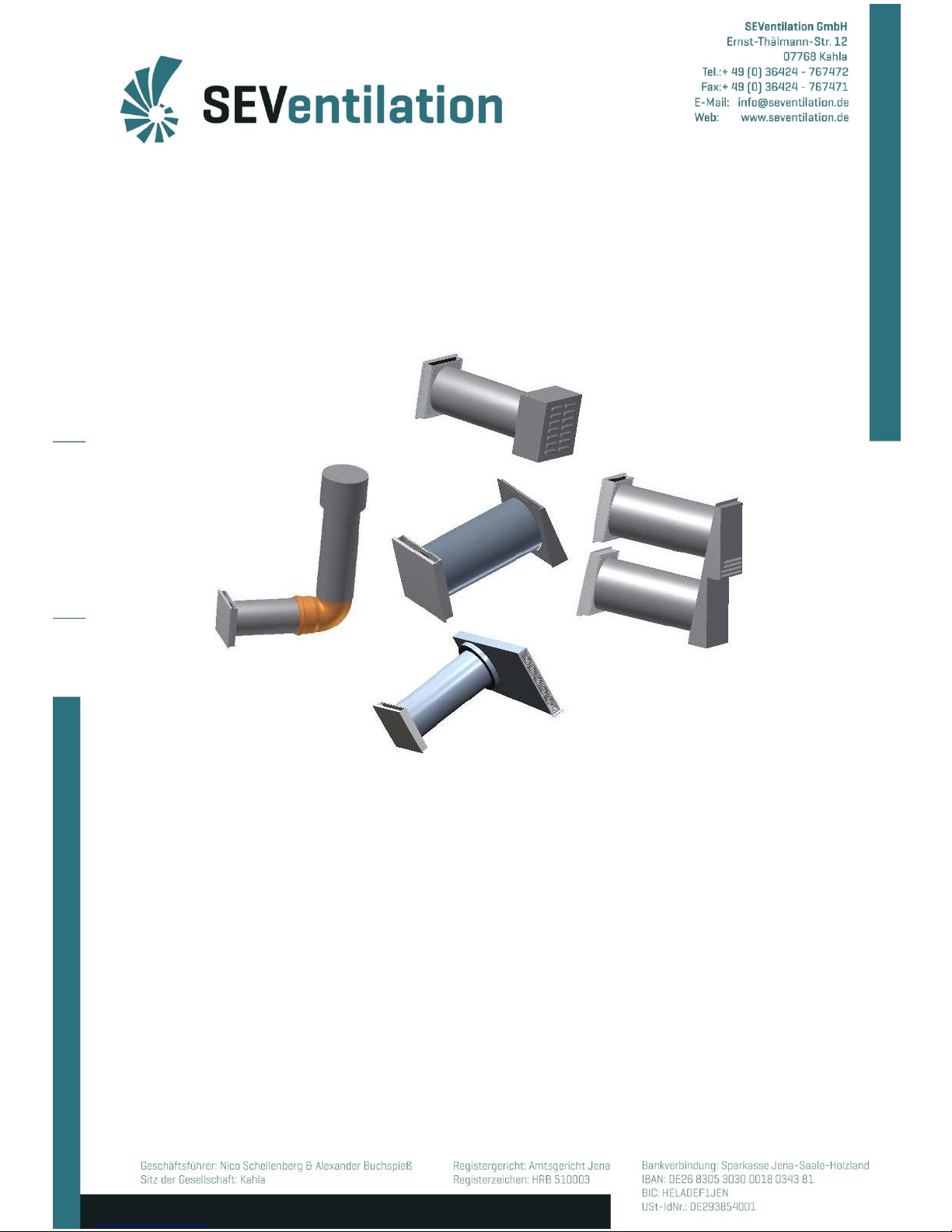
Operating Manual
SEVi 160 Series
(Intelligent ventilation system with heat recovery)
Production:
SEVentilation GmbH
E.-Thälmann-Str. 12
07768 Kahla
Tel.: +49 36424 767472 Fax: +49 36424 767471 Email: info@seventilation.de
As at: 10/2016
2
Notes
Explanation of the safety-relevant symbols and terms used in this manual:
Danger:
indicates a danger with a high risk which can cause
death or serious injuries if it is not avoided.
Warning:
indicates a danger with a mean level of risk which
can cause death or serious injuries if it is not
avoided.
Caution:
indicates a danger with a low level of risk which can
cause slight or moderate injuries if it is not avoided.
Note:
Failure to adhere to the instruction or guideline can
damage the device or affect the proper functioning
of the device.
For the purpose of this manual, the term qualified personnel refers to
persons who have the appropriate professional education to perform the
activities required (e.g. electrical installation, heating and ventilation
installation) and know the relevant standards and regulations.
For proper disposal of packaging, separate it according to the
specific material! If you want to dispose of the system, observe
the current provisions! Contact the local authority for detailed
information!
3
Contents
1. General information concerning the Operating Manual......................................................... 4
2. Operation ................................................................................................................................ 6
2.1 SEC-20 central control unit .............................................................................................. 6
2.2 SEC-Basic and SEC-20-BF .............................................................................................. 7
2.2.1 Determining the device type when using SEC-Basic .................................................... 8
2.2.2 Determining the device type when using SEC-20-BF .................................................. 8
3. Maintenance and service ...................................................................................................... 12
3.1 Maintenance intervals .................................................................................................... 12
3.2 Maintenance guidelines .................................................................................................. 13
3.3 Fault tracking .................................................................................................................. 15
Please, also observe the instructions given in the assemblymanuals
of the ventilation systems!
4
1. General information concerning the Operating Manual
Check the product for completeness (see packing slip) and transport damage immediately
after receiving it! The product must be stored at a safe and dry place!
Adhere to the instructions in this Operating Manual!
Please, observe the approval regulations and the applicable construction provisions as well
as the fire prevention regulation and accident prevention regulations of the Employers’
Liability Insurance Association when planning, installing and operating the system. When
planning the ventilation system, details must be discussed with the responsible chimney
sweeper and construction manager!
Before installation, contact your planner to get to know whether a RAL installation is
required.
Assembly works and electrical installations are to be carried out by qualified personnel!
Use the ventilation system only in compliance with the applications described in this
documentation and only in connection with components which have been recommended
and approved by the company SEVentilation and are specified in this documentation.
Modifications or reconstructions of the ventilation system are not permitted. The correct and
safe operation of the ventilation system is only possible, if it is properly transported, stored
and mounted as well as carefully operated and maintained. This documentation is part of the
ventilation system and must always be at hand. Observe all safety regulations included in this
documentation.
The manufacturer shall not be held liable for damages caused by improper installation,
connection and use of the system. The warranty will expire. The legal warranty periods shall
apply according the General Terms and Conditions!
Product description and instructions for use
The SEVi 160 ventilation system with heat recovery available in different variants is used for
controlled living space ventilation.
A SEVi 160 ventilation system includes at least 2 SEVi 160 fans and a control unit SEC-20.
Ideally, an even number of devices is to be installed (exception: SEVi 160 DUO).
Principle of heat recovery
5
The devices belonging to the ventilation systemare operated in opposite directions in the
heat recovery mode. This means that in pairwise operation each fan alternatively expels used
room air to the outside and replaces it by fresh air which has been pre-heated in the heat
accumulator. The direction of the fan is changed in intervals of 75 seconds. The ventilation
system is operated with 12 V and exclusively consists of high-quality materials.
In addition to the heat recovery mode, intensive brief ventilation is possible (permanent
intensive brief ventilation at fan stage 4) in which, depending on the installation condition of
the fans, a constant air stream is provided towards one direction to ventilate the room
without opening the window (noise protection).
The operation of the ventilation system is recommended throughout the year. In the
seasonsin which heating appliances are not necessary, the ventilation system acts in a
contrary manner. Here, summer operation (intensive brief ventilation, passive cooling) is
recommended, and in this mode, the generally lower inside air temperature of the morning
hours is maintained in the living space analogue to the principle of heat recovery.
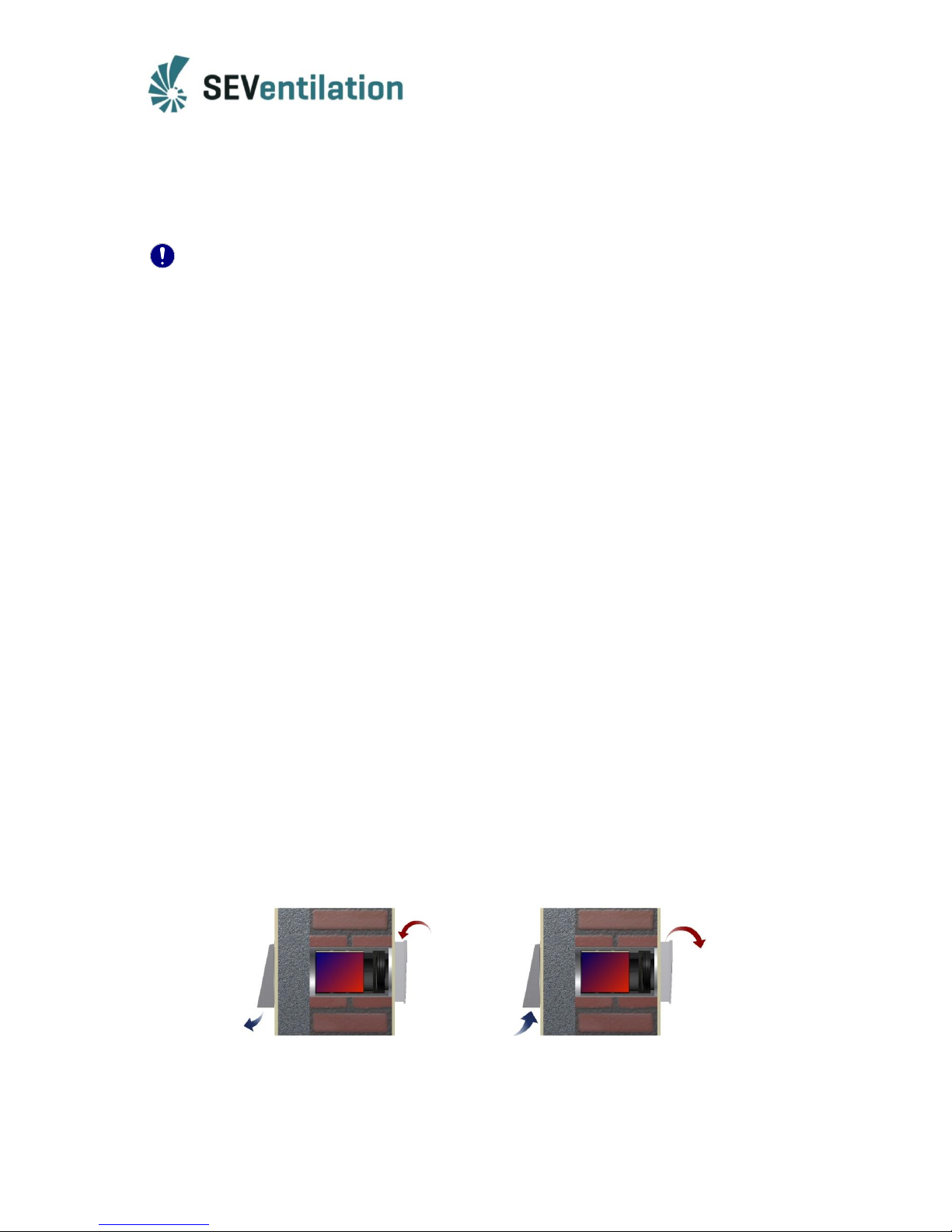
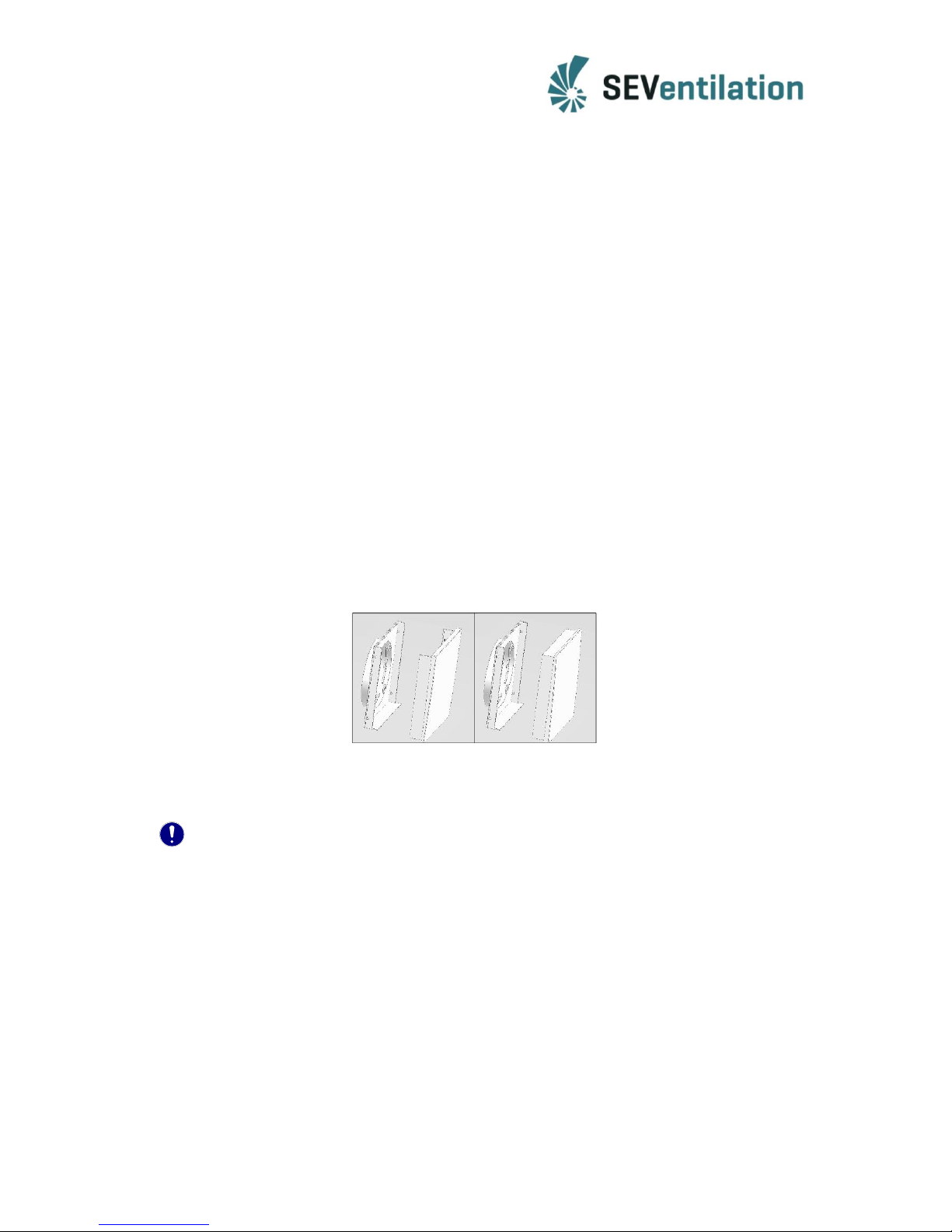
When the ventilation system is not in use (important during the heating season), the upper
part of the interior panel is to be turned by 180° to close the interior panel to avoid, for
example, that heat escapes out of the building in an uncontrolled manner and cold air enters
through the ventilation device in case of power failure or in special winter conditions.
Closure of the interior panel
Ideally, the opening of the interior panel faces upwards (avoidance of draught below the
interior panel).
Note:
The ventilation system is always controlled via the control unit.
The system must not be operated in rooms with high dust rate.
The system must not be operated in rooms in which decomposing gases are used.
The system is not suited for drying out buildings.
The ventilation system shall only be started up after the completion of the
construction works.
The ventilation system is to be closed during the construction works.
Temperature range of application: -20°C to +75°C
6
2. Operation
2.1 SEC-20 central control unit
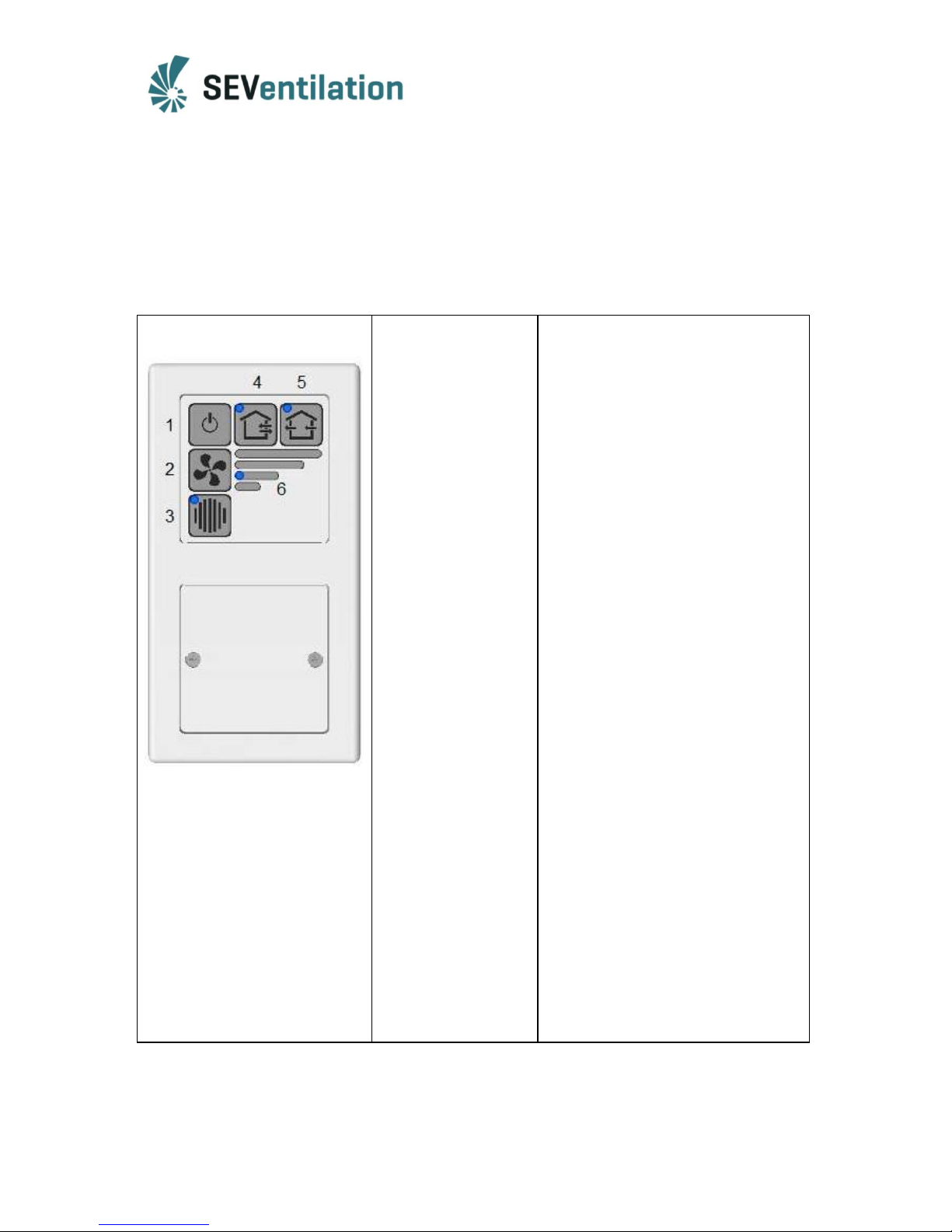
The ventilation systems of the SEVi 160 series are operated via the SEC-20 central control
unit. The keys desired are activated by a pressure on the membrane keypad. The operating
condition, the operating mode selected and the fan stage are indicated by a blue LED top left
on the corresponding keypad.
1 Device On/Off:
2 Selection of the fan
stage:
3 Acknowledgement/
filter change:
4 Operation in pairs:
5 Permanent intensive
brief ventilation
operation:
Snooze function:
When the device is switched off, the fan
continues to run for a short period of
time.
If this key is pressed repeatedly, the fan
stages 1 – 4 are run through. The fan
stage currently set is shown in the LED
display (6).
The end of the maintenance interval for
the dust filter is signalized by the LED.
The display will be reset if the key is
pressed for 5 seconds after the filter
change.
Heat recovery mode, normal operating
condition in the fan stages 1 – 4.
If this key is pressed, the ventilation
system jumps to a permanent intensive
brief ventilation mode which allows the
ventilation of a room without opening
the windows. For this purpose, stage 4
is set automatically.
The control unit is provided with a
snooze function by means of which the
system can be started with a delay of
60 minutes.
Set the desired operating mode
and fan stage.
Keep the keys 3 and 5 pressed
for at least 3 sec. (press key 3
first) ->only the LED of the
operating mode set (4 or 5)
is lit.
Press the keys (2), (4) or (5) to
terminate the snooze phase
prematurely.
 Loading...