

Page 1
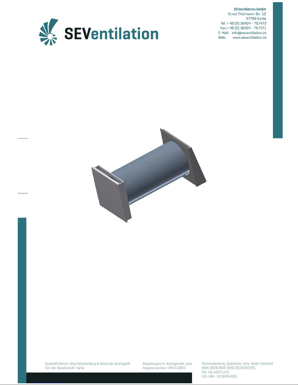
Assembly Manual
SEVi 160/SEVi 160 PLUS – Ventilation System
(Intelligent ventilation system with heat recovery)
Production:
SEVentilation GmbH
E.-Thälmann-Str. 12
07768 Kahla
As at: 10/2016
Page 2
2
Notes
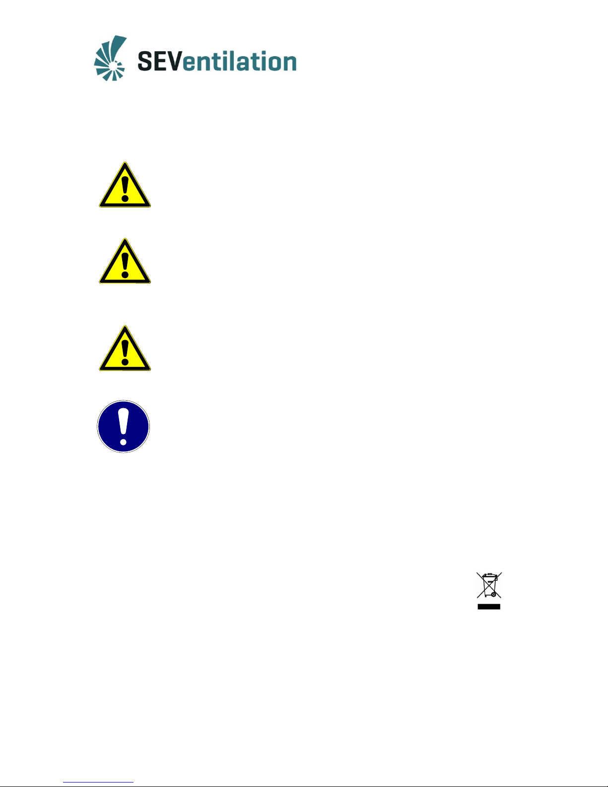
Explanation of the safety-relevant symbols and terms used in this manual:
Danger:
indicates a danger with a high risk which can cause
death or serious injuries if it is not avoided.
Warning:
indicates a danger with a mean level of risk which
can cause death or serious injuries if it is not
avoided.
Caution:
indicates a danger with a low level of risk which can
cause slight or moderate injuries if it is not avoided.
Note:
Failure to adhere to the instruction or guideline can
damage the device or affect the proper functioning
of the device.
For the purpose of this manual, the term qualified personnel refers to
persons who have the appropriate professional education to perform the
activities required (e.g. electrical installation, heating and ventilation
installation) and know the relevant standards and regulations.
For proper disposal of packaging, separate it according to the
specific material! If you want to dispose of the system, observe
the current provisions! Contact the local authority for detailed
information!
Page 3
3
Contents
1. General information referring to the Operating Manual ........................................................ 4
2. Scope of delivery .................................................................................................................... 5
2.1 Complete set ..................................................................................................................... 5
2.2 Completion set .................................................................................................................. 5
2.3 Preparation set .................................................................................................................. 5
2.4 PLUS variant (optional) ................................................................................................... 6
2.5 Shell construction support (optional) ............................................................................... 6
3. Assembly ................................................................................................................................ 6
3.1 Positioning of the wall opening ........................................................................................ 7
3.2 Installation process ........................................................................................................... 8
3.2.1 Producing the wall opening ....................................................................................... 8
3.2.2 Installing the fixation tube ....................................................................................... 10
3.2.3 Mounting the weather protection hood ................................................................... 11
3.2.4 Installing the fan drive ............................................................................................. 12
3.2.5 Mounting the interior panel ..................................................................................... 13
Page 4
4
1. General information referring to the Operating Manual
Check the product for completeness (see packing slip) and transport damage immediately
after receiving it! The product must be stored at a safe and dry place!
Adhere to the instructions in this Assembly Manual!
Please, observe the approval regulations and the applicable construction provisions as well
as the fire prevention regulation and accident prevention regulations of the Employers’
Liability Insurance Association when planning, installing and operating the system. When
planning the ventilation system, details must be discussed with the responsible chimney
sweeper and construction manager!
Before installation, contact your planner to get to know whether a RAL installation is
required.
Assembly works and electrical installations are to be carried out by qualified personnel!
Use the ventilation system only in compliance with the applications described in this
documentation and only in connection with components which have been recommended
and approved by the company SEVentilation and are specified in this documentation.
Modifications or reconstructions of the ventilation system are not permitted. The correct and
safe operation of the ventilation system is only possible, if it is properly transported, stored
and mounted as well as carefully operated and maintained. This documentation is part of the
ventilation system and must always be at hand. Observe all safety regulations included in this
documentation.
The manufacturer shall not be held liable for damages caused by improper installation,
connection and use of the system. The warranty will expire. The legal warranty periods shall
apply according the General Terms and Conditions!
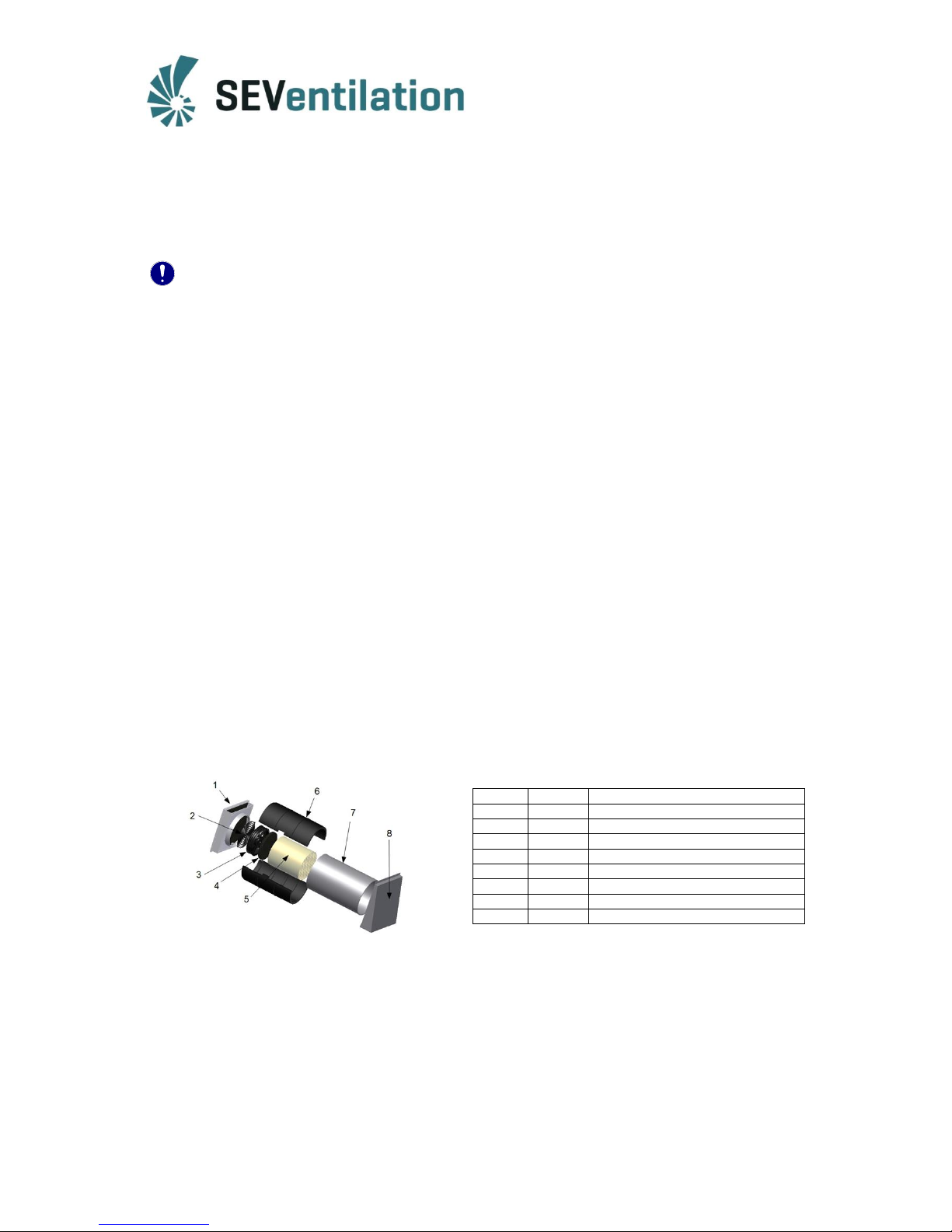
OBJECT
AMOUNT
DESIGNATION
1 1 interior panel with sound protection pad
2 1 safety grid
3 1 ventilator with acoustic decoupling
4 1 sound insulation element
5 1 heat accumulator
6 1 EPP casing (2-parts)
7 1 fixation tube
8 1 weather protection hood
SEVi 160 standard component drawing
The SEVi 160 ventilation system with heat recovery, which is available in different variants, is
used for controlled living space ventilation.
Page 5
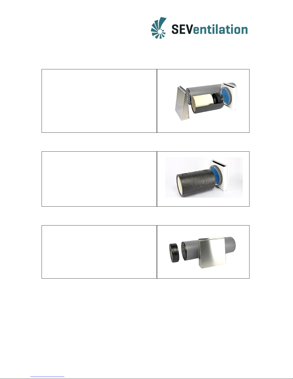
5
2.Scope of delivery
2.1 Complete set
- fixation tube, standard: 480 mm,
(optional:650 mm and 850 mm)
- fan drive
- interior panel
- weather protection hood
- protective disc
2.2 Completion set
- fan drive
- interior panel
2.3 Preparation set
- fixation tube (standard: 480 mm,
optional:650 mm and 850 mm)
- weather protection hood
- protective disc
- EPP cylinder
Page 6
6
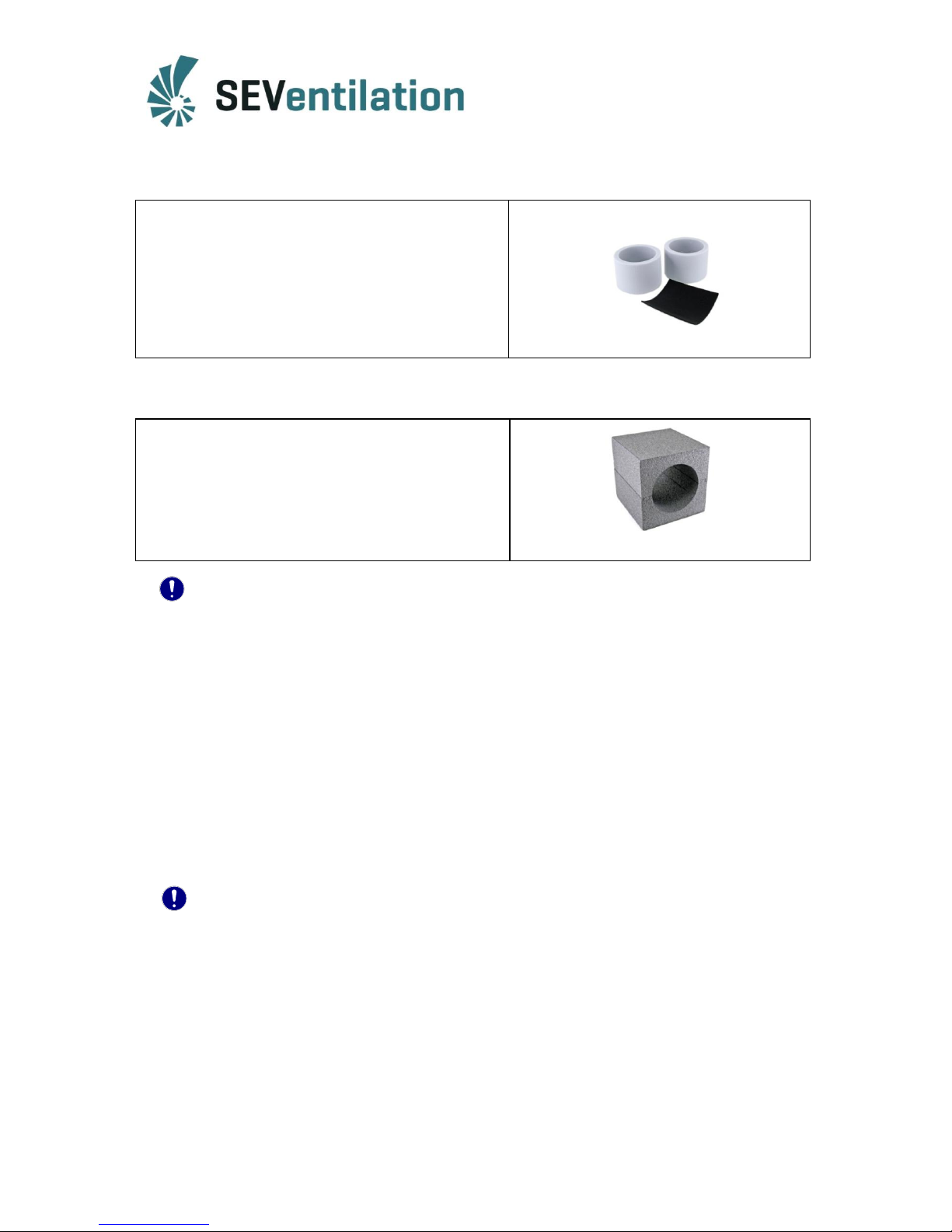
2.4 PLUS variant (optional)
- sound insulation element in weather
protection hood (is already mounted in
the weather protection hood)
- 2 x sound insulation element in interior
tube (can be adjusted to fixation tube
length)
2.5 Shell construction support (optional)
- shell construction supportZ160-RBT
Note:
Ventilation system is always controlled via the control unit.
System must not be operated in rooms with high dust rate.
System must not be operated in rooms in which decomposing gases are used.
System is not suited for drying out buildings.
The ventilation system shall only be started up after the completion of the
construction works.
The ventilation system is to be closed during the construction works.
Temperature range of application: -20°C to +75°C
3. Assembly
Note:
Study the complete Assembly Manual carefully before starting the installation to avoid
possible installation errors! The installation of the ventilation system requires prior thorough
planning by the responsible construction manager!
Faulty installation can cause trouble in the operation of the ventilation system and can void
the warranty. The ventilation system must be installed by qualified personnel!
All optional parts do not belong to the standard scope of delivery and are available at extra
charge.
Page 7
7
3.1 Positioning of the wall opening
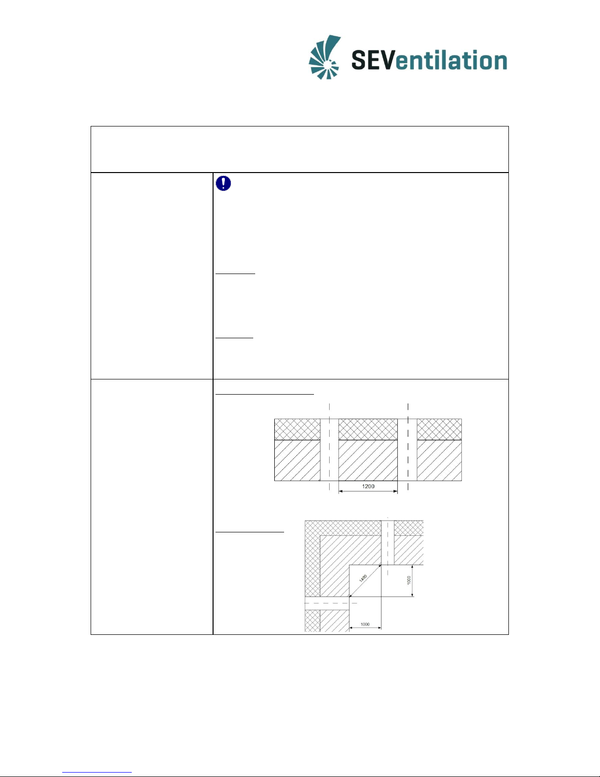
Generally, the place of installation is determined during the creation of the ventilation plan.
Observe the minimum distances indicated for the different installation variants! -> see also
page 16!
Minimum distance to
adjacent objects
(windows, doors, etc.)
Ensure that the minimum distances are maintained on both
sides of the wall! ->see page 16
The positioning aids on page 16 can be used for orienting at
window or door edges! Observe the kind of material of the wall!
Exterior: A clear minimum distance of 300 mm upwards is required
from the centre of the wall opening for mounting the weather
protection hood (or 200 mm from the upper edge of the lower part)
(The mounting weather protection hood will pushed downwards).
Interior: The distance from the centre of the wall opening to the
room ceiling must not be less than 350 mm because a clearance of
250 mm upwards is required for mounted interior panel.
Minimum distances
between two ventilation
devices (e.g. in case of
installation in the same
wall)
horizontal or vertical:
adjacent walls:
Page 8
8
3.2 Installation process
3.2.1 Producing the wall opening
When the position of the wall opening has been determined (3.1and p. 16), the opening
with a diameter of minimally 165 mm and maximally 170 mm (180 – 200 mm are possible in
case of subsequent plasterwork) is preferentially produced by a coredrill in the exterior wall.
For this purpose, the drilling direction from the inside to the outside is recommended. The
gradient to the outside must be considered for a bore diameter of 165 mm!
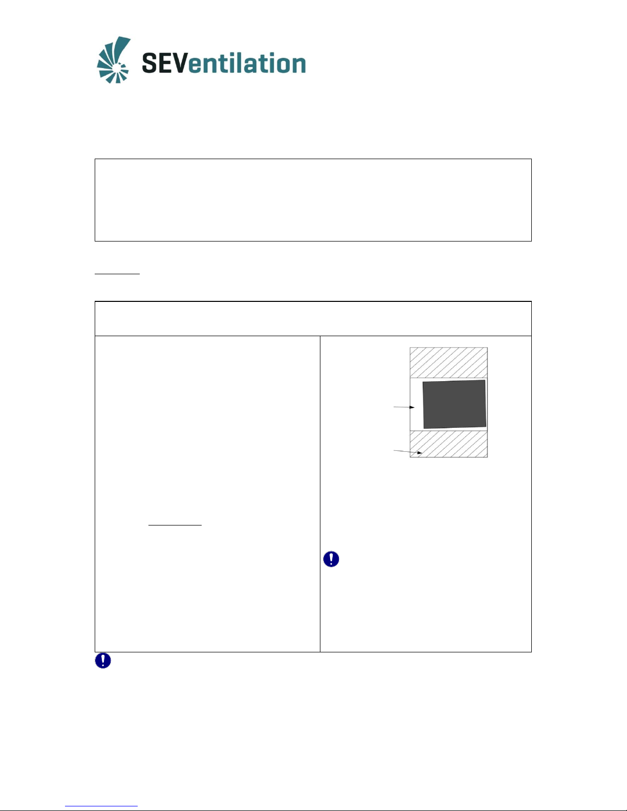
Optional: Use of the shell construction support Z160-RBT
Instead of being inserted through a tapping drill hole, the fixation tube can also be installed
into the wall by using the shell construction support Z160-RBT.
1. Produce the wall opening of
250 x 250 mm for the shell
construction support in the exterior
wall.
2. Mount one or several shell
construction support/s (depending on
the wall thickness) according to the
installation instruction for the fixation
tube. Pay attention to the gradient of
1-2% to the outside! Insert the
fixation tube before fixation and fix it
by using a mounting adhesive suited
for PP and EPS!
3. Flush-plaster the shell construction
support surfaces or adapt them to the
wall level. Reduce projections
according to 3.2.2 (interior: flush,
exterior: only the fixation tube shell
protrude by5 mm).
Exterior
Interior
Shell
construction
support (Observe
gradient to the
outside)
Wall
Note:
Follow
ing installation, the shell construction
support surface muss be adopted to the
walls by plasterwork or similar techniques!
Note: The use of suited insulation material anchor bolts is recommended for
mounting the weather protection hoods in combination with the shell
construction support!
Page 9
9
Note: Please, observe the Assembly ManualSEC-20, SEC-20-BF or
SEC-Touch!
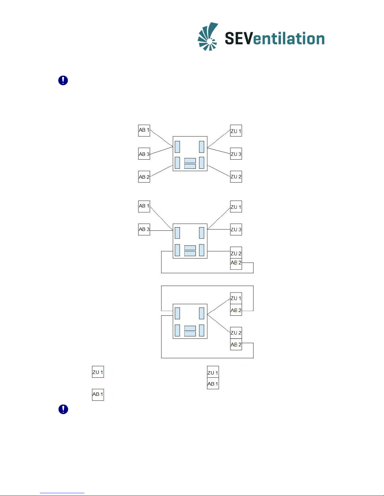
Note: An individual cable (LIYY 3 x 0.5 mm² or 3 x 0.75 mm²) is to be laid from
each fan to the distributor board! Two cables must be laid for the double fan
SEVi 160 DUO!
Examples for the allocation and combination SEVi 160 and
SEVi160DUO
SEVi 160 single device: fan pair 1
- start direction supply air
SEVi 160 single device: fan pair 1
- start direction exhaust air
SEVi 160 DUO: fan pair 1
- observe opposite start direction
A SEVi 160 DUO requires
2 supply lines!
Page 10
10
3.2.2 Installing the fixation tube
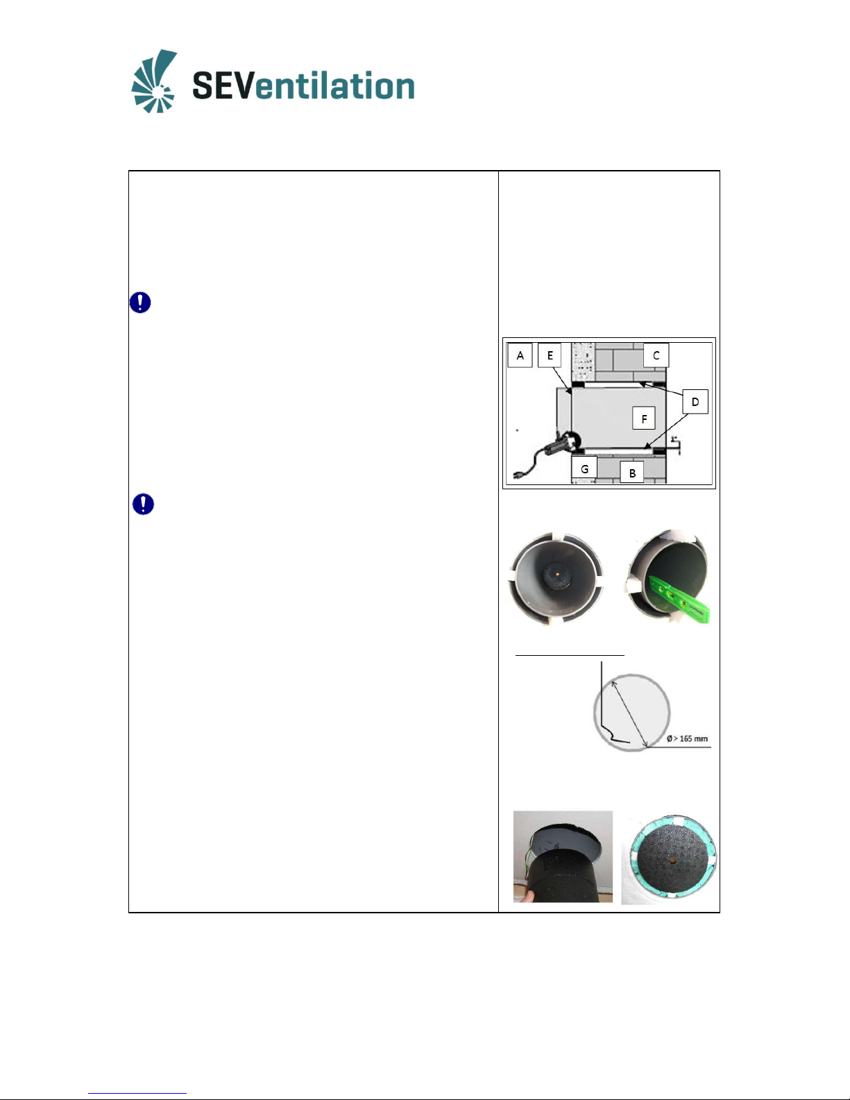
A – exterior
B – brickwork
C – interior wall area, incl. plastering/wall pater
D – foaming area
E – separation line
F – fixation tube
G – insulation, incl. plastering
Before the fixation tube is mounted into the wall,
a notch with a depth of about 3x10 mm is to be
produced on the inside to lead the cable (without
coating) in the fixation tube to the ventilator!
1. Insert the fixation tube (F) with a gradient of
about 1-2 % to the exterior by using cotter pins
(to be cut out of the piece of foamed polystyrene
included in the scope of delivery). Flush end of
the fixation tube on the interior wall side (C);
5 mm shall protrude on the exterior wall side (A).
Observe for installation performed before
plasterwork!
If the plasterwork has not been finished yet, a
protrusion on both sides according to the later
plasterwork thickness is to be taken into
consideration when cutting the fixation tube
length (after plastering, the tube must be flushmounted with the plaster inside and protrude by
5 mm on the exterior). Notch the tube on the
interior wall side (Remove cable coating!) to lead
the connection cable through.
2. Slide the fan drive or EPP cylinder into the tube
before foaming to prevent a tube deformation.
3. Adhere possible vapour barrier with fixation
tube.
4. Mount the protective disc onto the tube end.
5. Fill the clearance between the tube and the wall
by using a two-component assembly frame foam
(protect the storefront against the foam). Cut off
protruding foam and cotter pins after completed
drying.
Tools required:
- circular saw element for drilling
machine,
- angle grinder with plastic cut-off
wheel or handsaw,
- level
1.
Remove cable coating!
2. - 5.
Cable LIYY 3 x 0,5 mm²
Page 11
11
3.2.3 Mounting the weather protection hood
The stainless steel weather protection hood protects the ventilation system so that
precipitation or rain cannot directly enter the system. Additional measures must be taken
for increased requirements, e.g. in case of salty air, chlorine-containing air or rust film!
Weather protection hood: - upper part + lower part of stainless steel, bright
(optionally available: white powder-coated RAL 9010 or iron
grey powder coated RAL 7011)
- sealing tape, 4 stainless steel screws + anchor bolts for
assembly
(optional: insulation material anchor bolts and adjustment
frame 110 mm)
Required tools: - impact drill, level, screw driver TX 20, knife
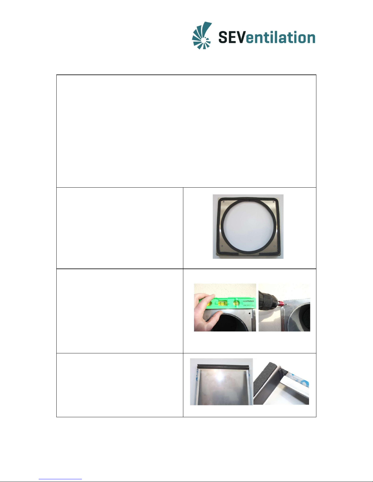
1. Fix the sealing tape at the rear side
of the lower part (adjustment of wall
and lower part).
A distance of about 60 mm is to be
maintained centrally in the lower
area! The inner sealing tape and the
outer sealing tape must not contact
each other in this area!
2. Mount the lower part horizontally at
the facade(drip edge downwards to
the outside). For doing this, put the
lower part onto the protruding
fixation tube, align it by using the
level, mark bore holes and mount it
by using the anchor bolts and screws
included in the scope of delivery.
3. Fix the sealing tape at the rear side
of the upper part (hood) and in the
edges (strips with a length of about
1 cm each).
Page 12
12
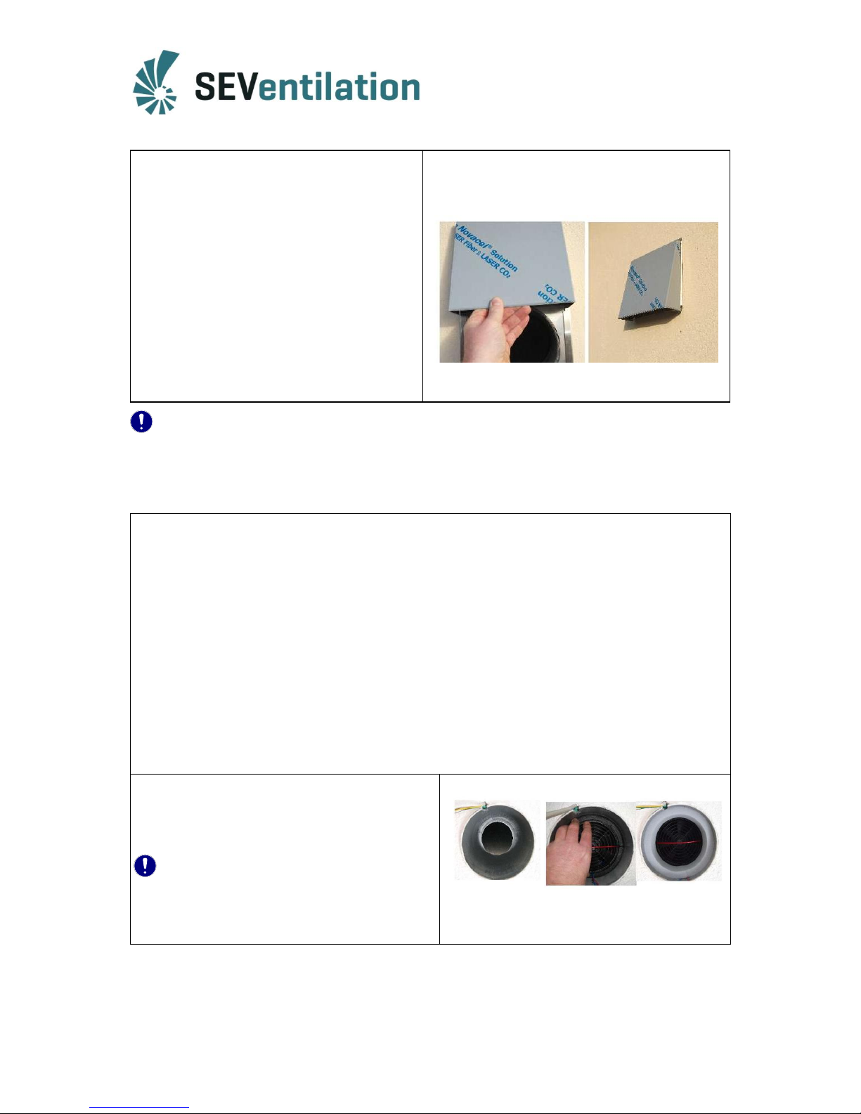
4. Slide the hood from above onto the
lower part after the completion of
the facade works (depending on the
accessibility, the protection film of
the stainless steel type can also be
removed after finishing paintwork).
If required, the weather protection
hood can be additionally sealed to
the wall above and to the sides by a
permanently elastic sealant).
For highly-insulated outer facades, sufficient protection against algae growth must be
ensured!
3.2.4 Installing the fan drive
Insert the fan drive up to the end of the tube at the weather protection hood so that the
ceramic part shows to the exterior wall side, i.e. insert it as far as possible towards the
exterior wall.
If necessary, remove the burling before insertion (in case of very difficult insertion).
The sound insulation element optionally available for the interior tube of the SEVi 160
PLUS is positioned in the fixation tube after sliding in the fan drive. (260 mm are to be
reduced from the length of the fitted fixation tube for the length required for the sound
insulation element.)
The fan drive comprises a filter insert, a reversing and moisture-protected ventilation unit,
heat accumulator, protection grid, sound insulation element.
A pollen protection filter is optionally available.
Insertion of the fan drive
(The image on the right shows the optionally
available sound insulation element of the PLUS
variant.)
Important:
The condensation discharge (identifiable by
the ventilator cables) must be positioned at
6 o’clock!
Page 13
13
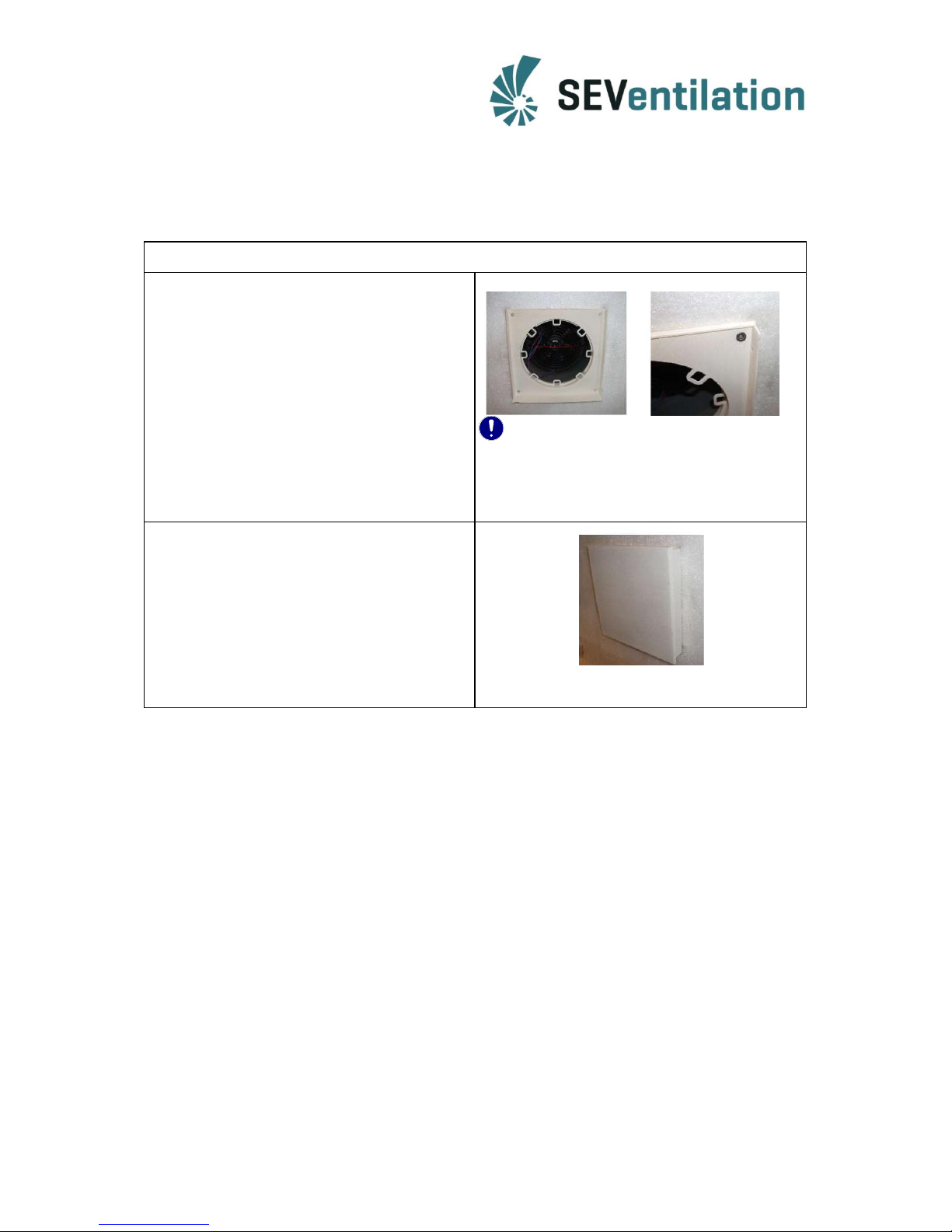
3.2.5 Mounting the interior panel
(opening upwards)
The interior panel is supplied completely with dust filter in opened condition.
1. Insert the lower part of the interior
panel into the tube. If necessary, the
lower part can be screwed to the
wall. For this purpose, four prepared
holes are provided at the rear side
and can be easily penetrated. The
bore holes are marked after aligning
the lower part by means of the level.
After mounting the lower part, the
upper part can simply be slid onto it.
Note: When using the optionally
available glass interior panel, it is
recommended to screw it to the
wall!
2. The opening of the interior panel
should ideally show upwards (to
avoid draught effects). If the
installation conditions do not allow
this, the interior panel (complete) can
also be turned to the right, left or
downwards.
Page 14
14
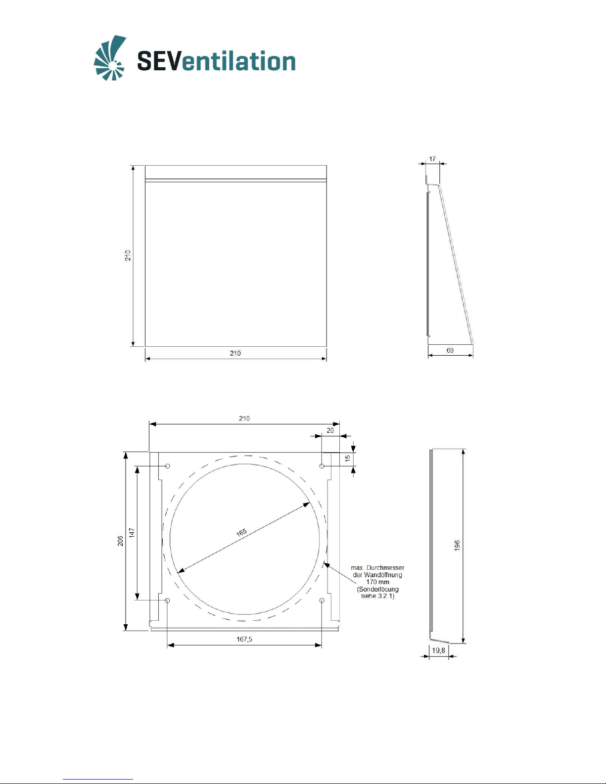
Dimension of weather protection hood
upper part
lower part
Page 15
15
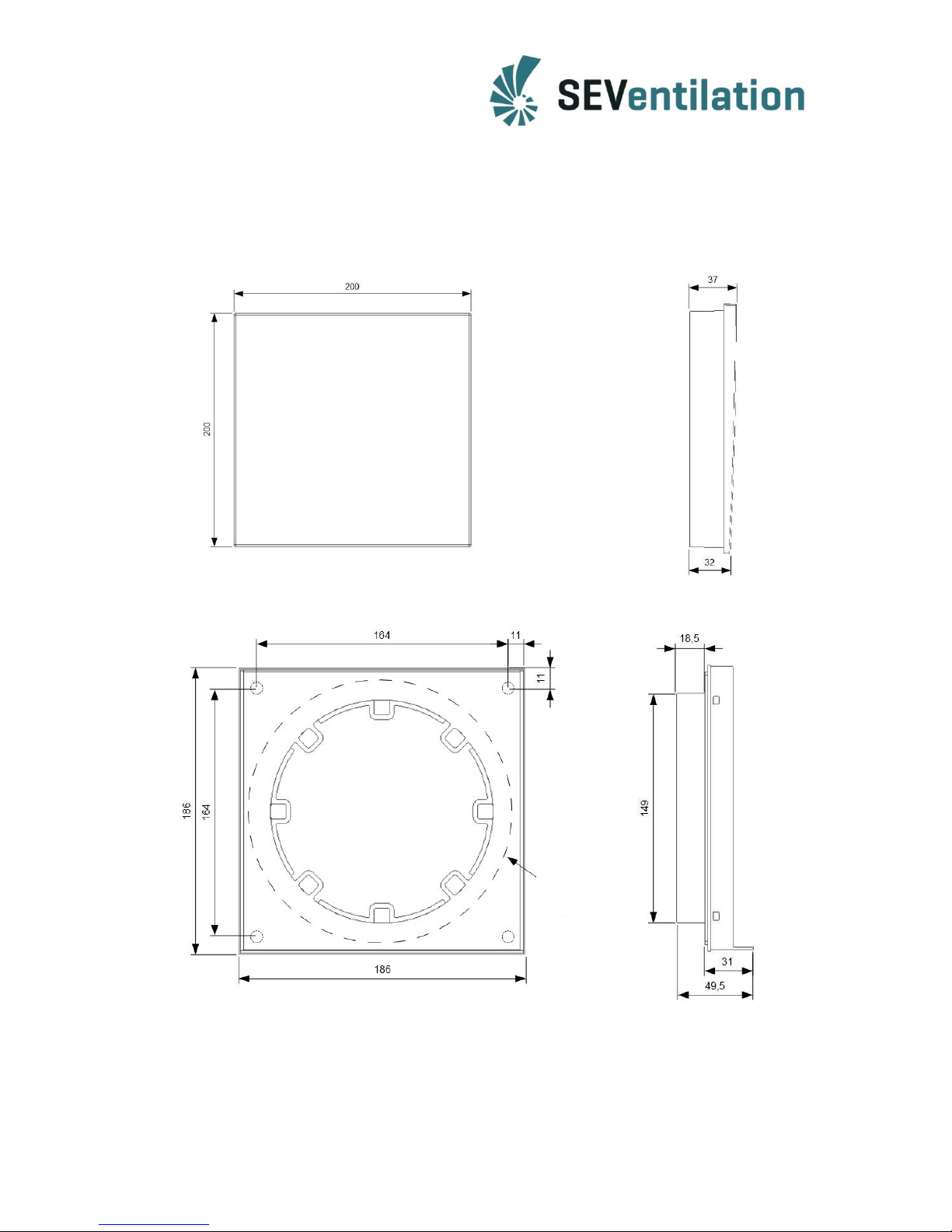
Dimension of the interior panel
upper part
lower part
max. diameter of wall
opening: 170 mm
(special-purpose
solution see 3.2.1)
Page 16
16
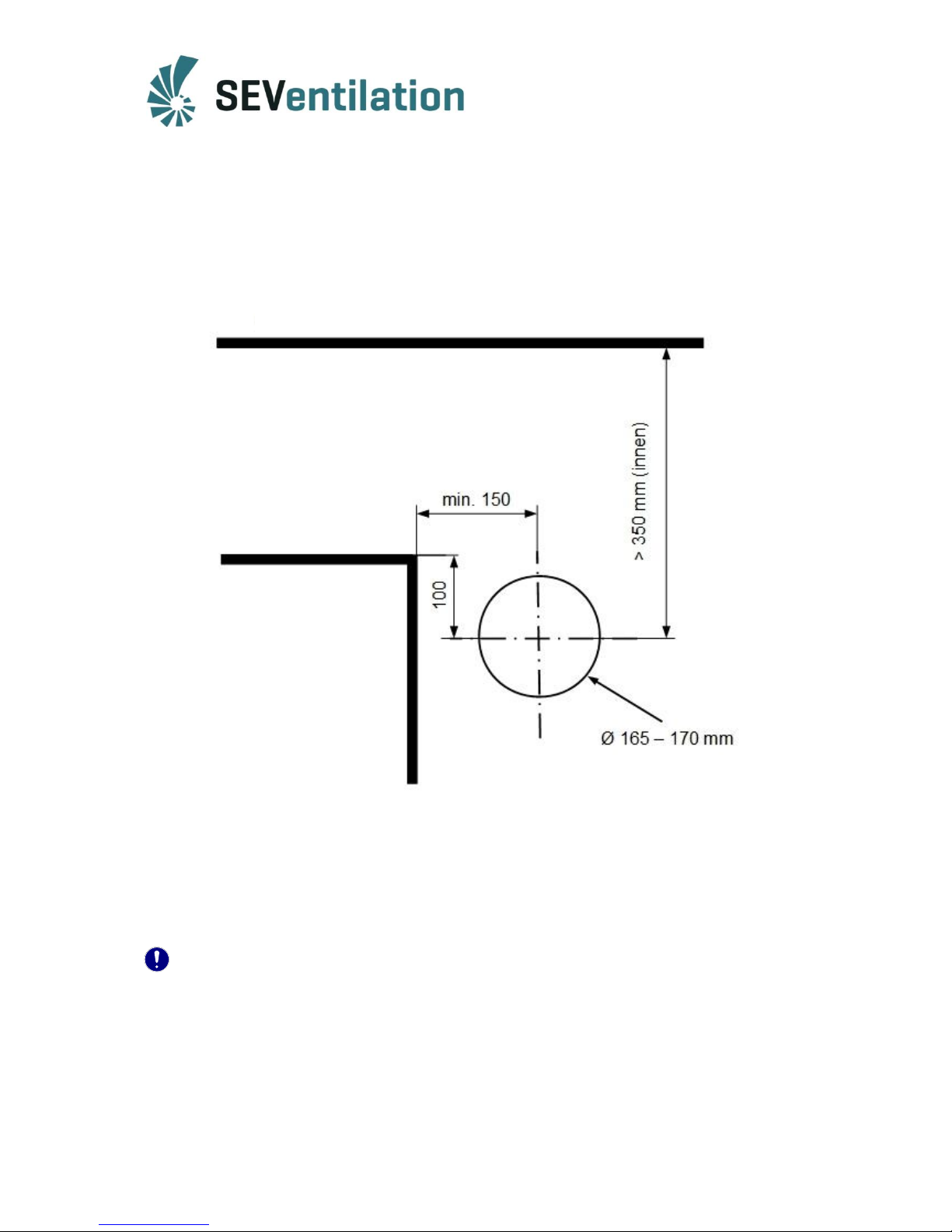
Positioning aid for core hole drilling
The lateral distance of at least 150 mm is to be considered as an approximate value and can,
depending on the situation, be increased!
Note concerning the exterior hood: On the exterior, a free space of at least 300 mm
must be kept above the hood for sliding on the
upper part!
Room ceiling (inside)
Protruding objects, edges, projections (outside)
Door, window, etc.
Page 17
17
EC Declaration of Conformity
The company
SEVentilation GmbH
E.-Thälmann-Str. 12-14
07768 Kahla
Germany
declares under its sole responsibility that the products:
type: SEVi 200 / SEVi 200U / SEVi 200L /SEVi 160 / SEVi 160DUO / SEVi 160U /
SEVi 160L / SEVi 160R / SEVi 160CE / SEVi 160RO / SEVi 160ALD / A160
(decentral ventilation devices with and without heat recovery),
to which this declaration refers, comply with the following standards and normative documents:
EN 55014 -1; 2006
EN 55014 -2; 1997, +A1; 2001
EN 61000-6-1, 2007; Generic Standards EMC – Immunity
EN 61000-6-3, 2007; Generic Standards EMC – Emission Standard
EN 61000-3-2, 12.2001; Low-Frequency System Perturbation
EN 61000-3-3, 1.1998
EN 60335-1, EN 60335-2-65; (safety of household and similar electrical appliances)
according to the provisions in the Directive 2004/108/EC or (EMC 2008), the Directive 2006/95/EC (Low Voltage
Directive) and the RoHS Directive 2002/95/EC.
The decentral ventilation systems: “SEVi 200 / SEVi 200U / SEVi 200L /SEVi 160 /
SEVi 160DUO / SEVi 160U / SEVi 160L / SEVi 160R / SEVi 160CE / SEVi 160RO / SEVi 160ALD / A160” with and
without heat recovery are used for the ventilation of apartments/accommodation units.
Kahla, 10/12/2015
Dipl.Wirt.Ing. (FH)* Nico Schellenberg
*Graduate Industrial Engineer
Page 18
18
The manufacturer reserves the right to change technical details!
Production:
SEVentilation GmbH
E.-Thälmann-Str. 12
07768 Kahla
Germany
Telephone: +49 36424 767472 Fax: +49 36424 767471 Email: [email protected]
 Loading...