

Page 1

Assembly Manual
Central Control Unit SEC-20-BF
(with humidity sensor)
Production:
SEVentilation GmbH
E.-Thälmann-Str. 12
07768 Kahla
As at: 11/2016
Page 2
2
Notes
Explanation of the safety-relevant symbols and terms used in this manual:
Danger:
indicates a danger with a high risk which can cause
death or serious injuries if it is not avoided.
Warning:
indicates a danger with a mean level of risk which
can cause death or serious injuries if it is not
avoided.
Caution:
indicates a danger with a low level of risk which can
cause slight or moderate injuries if it is not avoided.
Note:
Failure to adhere to the instruction or guideline can
damage the device or affect the proper functioning
of the device.
For the purpose of this manual, the term qualified personnel refers to
persons who have the appropriate professional education to perform the
activities required (e.g. electrical installation, heating and ventilation
installation) and know the relevant standards and regulations.
For proper disposal of packaging, separate it according to the
specific material! If you want to dispose of the system, observe
the current provisions! Contact the local authority for detailed
information!
Page 3

3
Contents
Contents
1. General information concerning the Installation Manual....................................................... 4
2. Standard scope of delivery ..................................................................................................... 5
3. Assembly ................................................................................................................................ 5
3.1 Connectivity options ........................................................................................................ 7
3.2 Terminal assignments of SEVi 160 and SEVi 160DUO .................................................. 8
3.3 Terminal assignments of SEVi 160/SEVi 160DUO and SEVi 160DUO MINI ............... 9
3.4 Assembly process ........................................................................................................... 10
3.5 Fan connection ............................................................................................................... 10
3.6 Functional overview ....................................................................................................... 11
3.7 Device types for the SEC-20-BF .................................................................................... 12
3.8 Activating/changing the humidity feature ...................................................................... 14
3.9 Combination with surface-mounted housing (optionally available) .............................. 15
Page 4
4
1. General information concerning the Installation Manual
Check the product for completeness (see packing slip) and transport damage immediately
after receiving it! The product must be stored at a safe and dry place!
Adhere to the instructions in this Assembly Manual!
Please, observe the approval regulations and the applicable construction provisions as well
as the fire prevention regulation and accident prevention regulations of the Employers’
Liability Insurance Association when planning, installing and operating the system. When
planning the ventilation system, details must be discussed with the responsible chimney
sweeper and construction manager!
Before installation, contact your planner to get to know whether a RAL installation is
required.
Assembly works and electrical installations are to be carried out by qualified personnel!
Use the ventilation system only in compliance with the applications described in this
documentation and only in connection with components which have been recommended
and approved by the company SEVentilation and are specified in this documentation.
Modifications or reconstructions of the ventilation system are not permitted. The correct and
safe operation of the ventilation system is only possible, if it is properly transported, stored
and mounted as well as carefully operated and maintained. This documentation is part of the
ventilation system and must always be at hand. Observe all safety regulations included in this
documentation.
The manufacturer shall not be held liable for damages caused by improper installation,
connection and use of the system. The warranty will expire. The legal warranty periods shall
apply according the General Terms and Conditions!
A SEVi 160/200 ventilation system includes at least 2 SEVi 160/200 fans and a SEC-20-BF
control unit. Ideally, an even number of devices (max. 6) is to be installed (exception: SEVi
160 DUO (max. 3)). The ventilation system is operated by a direct voltage of 12 V.
Notes:
The ventilation system is always controlled via the control unit.
The humidity level (can be activated optionally) is always determined at the control
unit
The system must not be operated in rooms with high dust rate.
The system must not be operated in rooms in which decomposing gases are used.
The system is not suited for drying out buildings.
The ventilation system shall only be started up after the completion of the
construction works.
The ventilation system is to be closed during the construction works.
Temperature range of application: 0°C to 40°C, max. 95% RH
Page 5
5
2. Standard scope of delivery
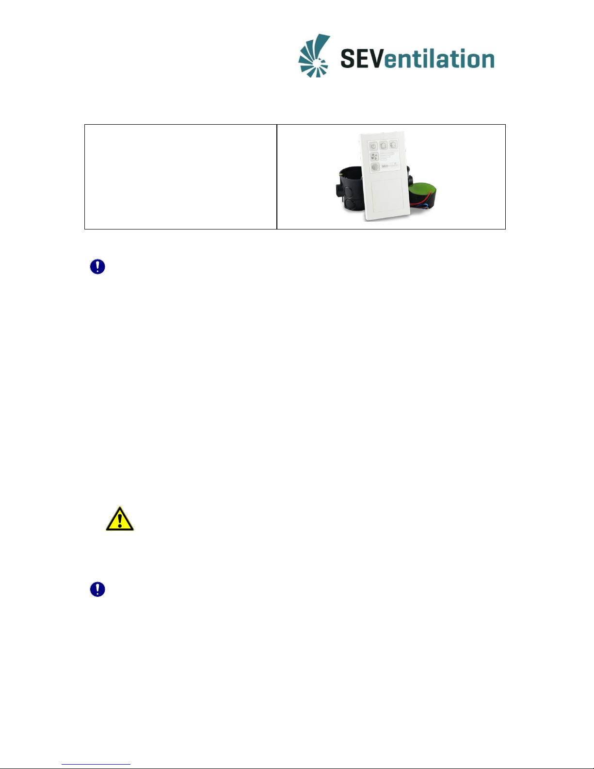
- operator control unit SEC-20-BF
- switch-mode power supply
- 2 x flush-mounted socket with a
depth of62 mm with device screws
- double frame
3. Assembly
Note:
Study the complete Assembly Manual carefully before starting the installation to avoid
possible installation errors! The installation of the ventilation system requires prior thorough
planning by the responsible construction manager!
Faulty installation can cause trouble in the operation of the ventilation system and can void
the warranty. The ventilation system must be installed by qualified personnel!
Important for operation with humidity feature:
The permanent accessibility of the components must be guaranteed.
Installation in humidors: The power-supply unit and the operator control unit
belonging to it must not be installed in the zones 0, 1 and 2 according to the German
regulation DIN 57100/VDE 100 Part 701!
The operator control must not be installed and operated directly next to heat sources
(heating unit, cooker or oven) at which the temperature can exceed 40°C (no direct
sunlight either)!
The operator control can be installed in the direct humidity area (next to washbasin,
tub or shower)!
Danger: All works shall only be carried out when the system is in de-energized
condition!
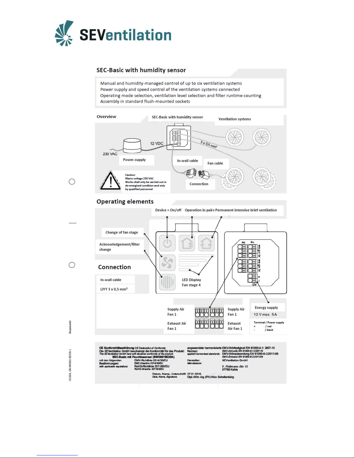
Adhere to the installation instructions of this manual. Moreover, a connection plan is added
to the operator control unit.
tools required: slot cutter, drill bit for installing flush-mounted sockets,screw drivers
Note: When installing the devices it is absolutely necessary to ensure star-shaped
wiring!
Page 6
6
Page 7
7
3.1 Connectivity options
The central control unit SEC-20-BF can be used for operating the fans of the SEVi 200 and
SEVi 160 series. Moreover, theSEVi 160DUO MINI (available from autumn 2016)can be
operated by using the SEC-20-BF.
Furthermore, the central control unit can be used as a humidity sensor.
Specific feature: Die terminal assignment of the spring-type terminals depends
on the fan models to be operated!
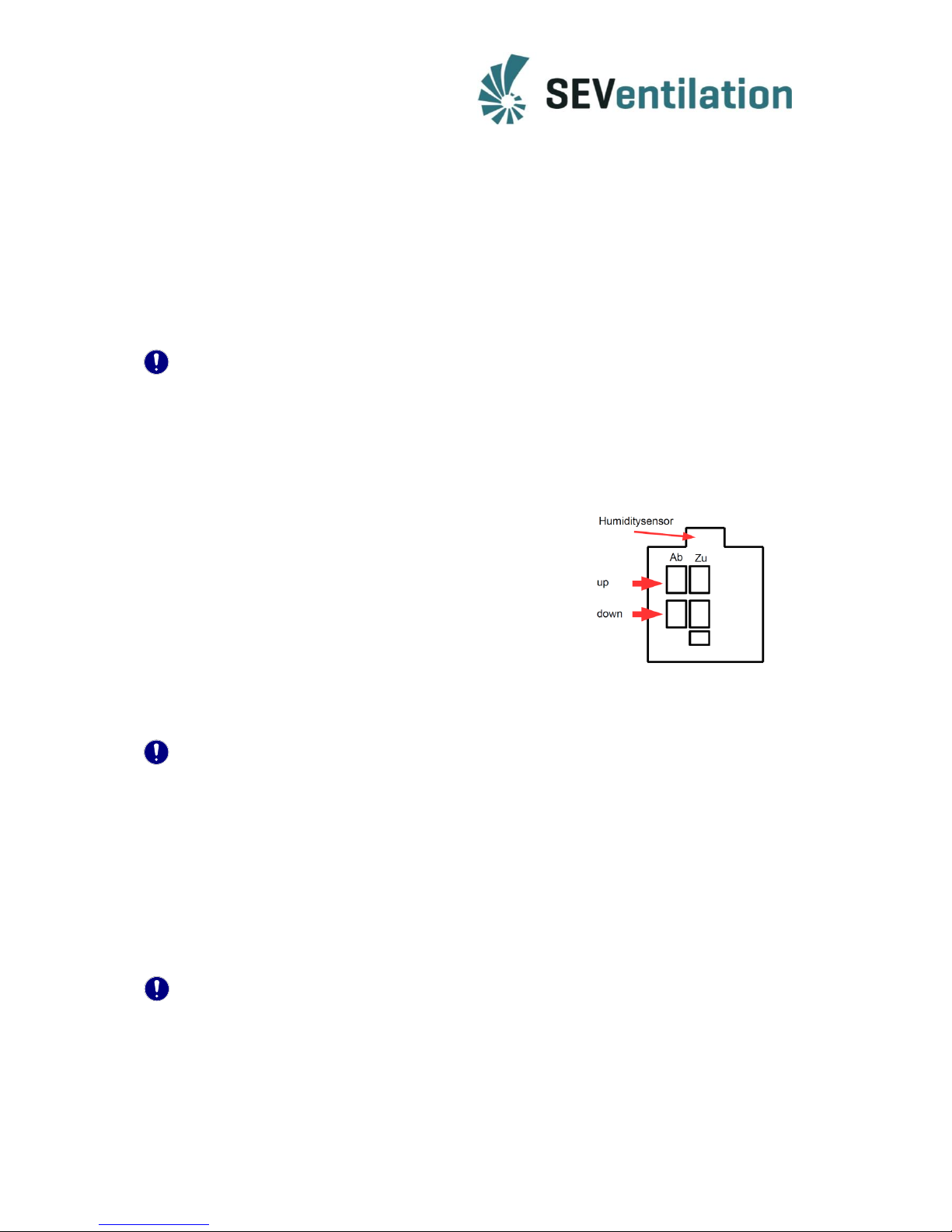
The fan terminals on the rear side of the operator control unit are separated in air incoming
side (Zu) and air discharge side (Ab) on the one hand, and on the other hand in top (oben)
and bottom (unten).
Air income and air discharge refer to the start direction
or the intensive brief ventilation operation. A fan which
is connected on the air incoming side, will work
according to the air incoming mode in intensive brief
ventilation or permanent ventilation operation; a fan
which is connected on the air discharge side will
transport the consumed air correspondingly.
The bottom connecting terminals must be used for operating the SEVi 160DUO MINI
ventilation system.
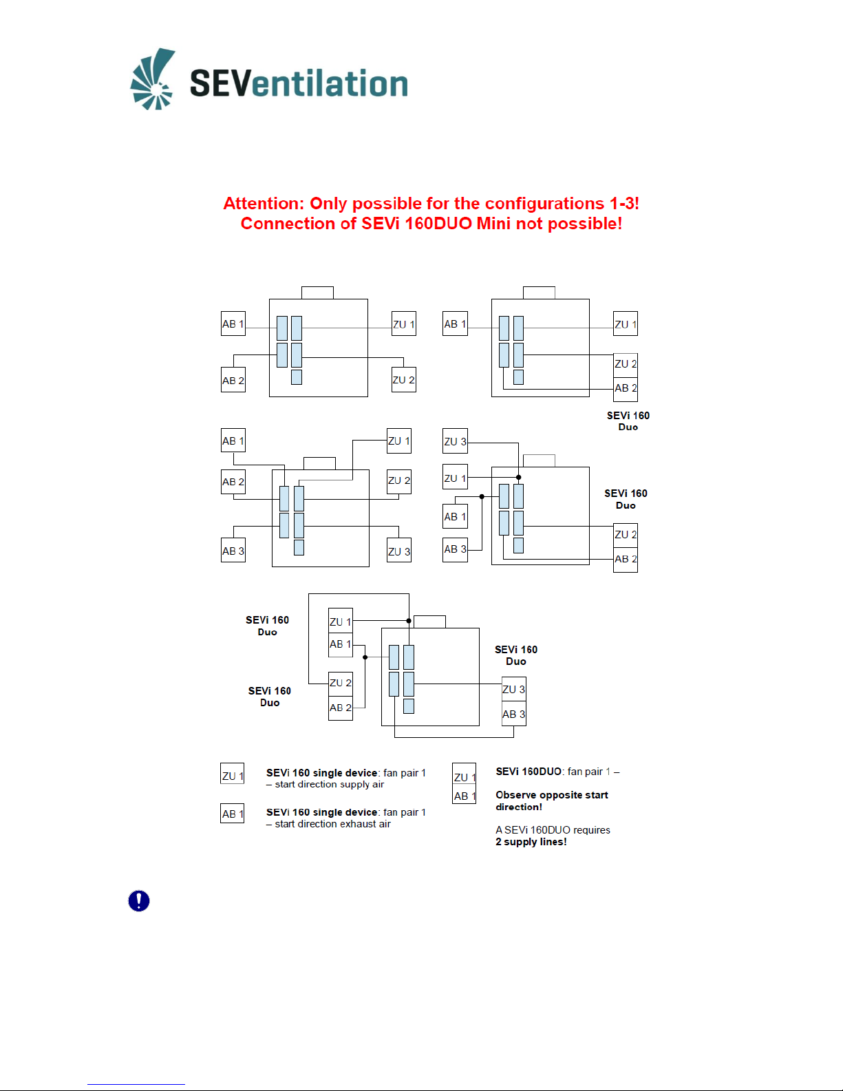
Note: SEVi 160 fans (without SEVi 160DUO MINI) can be operated in the
configurations 1 - 3 by using the top and bottom terminals!
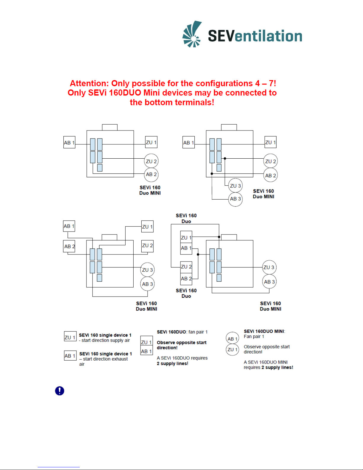
The sole operation of the SEVi 160DUO MINI or the simultaneous
operation of SEVi 160 systems and SEVi 160DUO MINI fans requires
the selectin of one of the configurations 4 - 7 and the appropriate
assignment of the connecting terminals!
Depending on the device types used and the operating modes desired, the configurations
indicated on pages13/14 under 3.7 are to be set.
Note: An individual cable (LIYY 3 x 0.5 mm² or 3 x 0.75 mm²) is to be laid from each
fan (SEVi160/200) to the distributor board! Two cables must be laid for the
double fans SEVi 160 DUO and SEVi 160DUO Mini!
max. length of the in-wall cable: 30 m
Page 8
8
3.2 Terminal assignments of SEVi 160 and SEVi 160DUO
Note: An individual cable (LIYY 3 x 0.5 mm² or 3 x 0.75 mm²) is to be laid from
each fan (SEVi 160/200) to the distributor board! Two cables must be
laid for the double fan SEVi 160DUO!
Page 9
9
3.3 Terminal assignments of SEVi 160/SEVi 160DUO and SEVi 160DUO MINI
Note: An individual cable (LIYY 3 x 0.5 mm² or 3 x 0.75 mm²) is to be laid from
each fan (SEVi 160/200) to the distributor board! Two cables must be
laid for the double fans SEVi 160 DUO and SEVi 160 DUO MINI!
Page 10
10
3.4 Assembly process
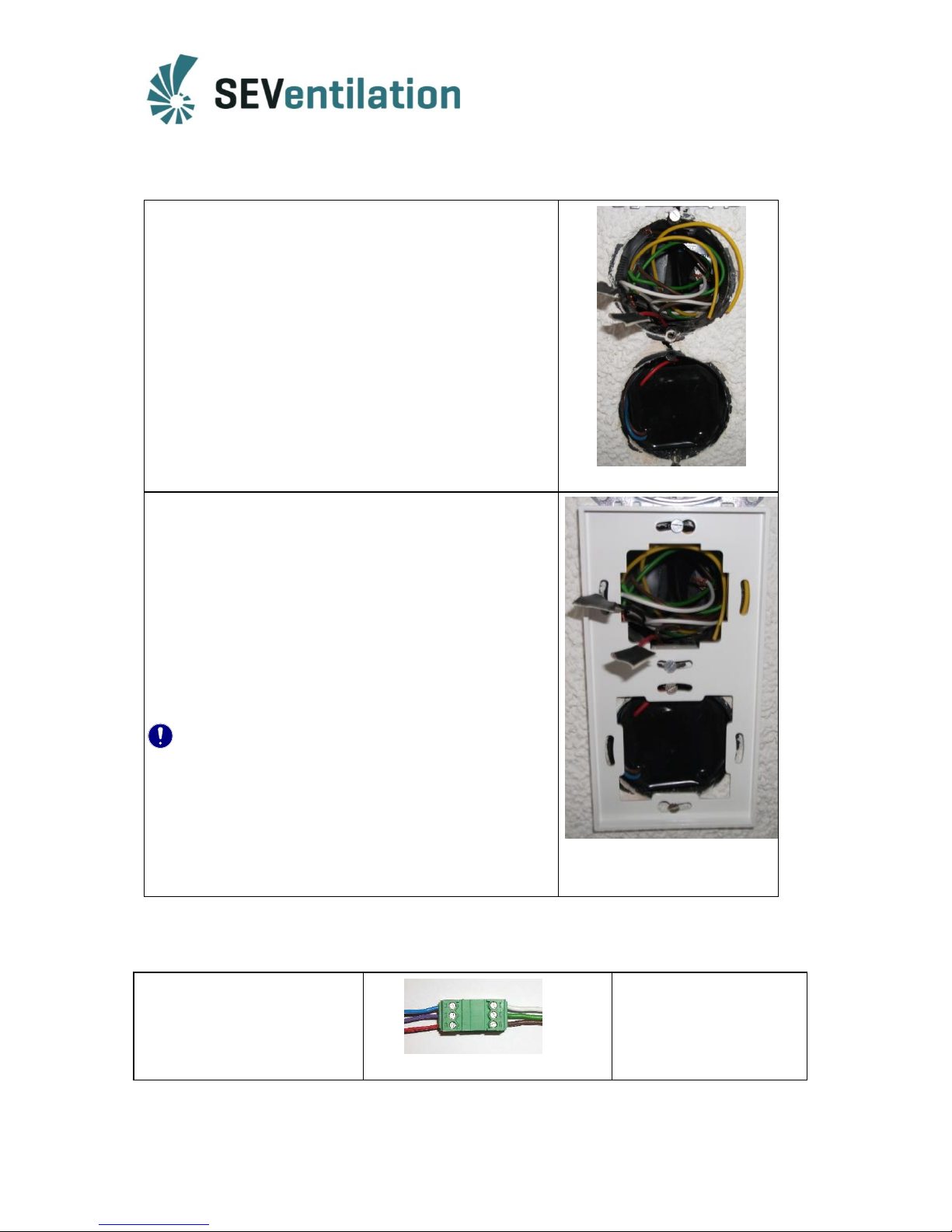
1. Install the flush-mounted sockets
upper socket for the operator control unit (fan
connection) and lower socket for switch-mode power
supply
(Assembly of the double frame also vertically
possible; please see page 16 for surface-mounted
solution!)
2. Install the switch-mode power supply
Install it such that the 12 V output and the 230 V
input are not on the same side of the switch-mode
power supply! (Position 230 V below!)
Lay the 12 V connection upwards.
3. Mount the lower part of the blind frame
The lateral openings must not be positioned above
the flush-mounted socket with the power supply!
Connect the in-wall cables(min. 3x0.5 mm²) of the
fans at the operator control unit according to the
existing fan types (see page 7)
4. Lead the connected operator control with humiditysensor unit diagonally through the opening in the
upper part of the blind frame; position the operator
control unit placed in the upper part and push it on
the lower part.
Note:
To release the operator control unit, grasp the cover
frame in the lower half and remove it carefully in
vertical direction until the operator control unit can be
taken from the lower part together with the upper
part; try it several times if required.
Do not use any tool for this purpose!
3.5 Fan connection
Connecting plug to the ventilator (fan)
Connection in-wall cable and
ventilator
Terminal/Cable↔Fan
br/brown red
gn/green violet
ws/white blue
Page 11
11
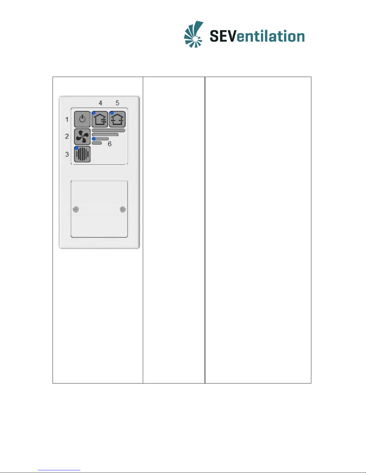
3.6 Functional overview
1 Device On/Off:
2 Selection of the fan
stage:
3 Acknowledgement/
filter change:
4 Operation in pairs:
5 Permanent intensive
brief ventilation
operation:
Snooze function:
When the device is switched off, the fan
continues to run for a short period of
time.
If this key is pressed repeatedly, the fan
stages 1 – 4 are run through. The fan
stage currently set is shown in the LED
display (6).
The end of the maintenance interval for
the dust filter is signalized by the LED.
The display will be reset if the key is
pressed for ca. 5 seconds after the filter
change.
Heat recovery mode, normal operating
condition in the fan stages 1 – 4*.
*depending on the device type, see 3.7
If this key is pressed, the ventilation
system jumps to a permanent intensive
brief ventilation mode which allows the
ventilation of a room without opening
the windows. For this purpose, stage 4*
is set automatically.
* depending on the device type, see 3.7
The control unit is provided with a
snooze function by means of which the
system can be started with a delay of
60 minutes.
Set the desired operating mode
and fan stage.
Keep the keys 3 and 5 pressed
for at least 3 sec. (press key 3
first) -> only the LED of the
operating mode set (4 or 5) is lit.
Press the keys (2), (4) or (5) to
terminate the snooze phase
prematurely.
Page 12
12
3.7 Device types for the SEC-20-BF
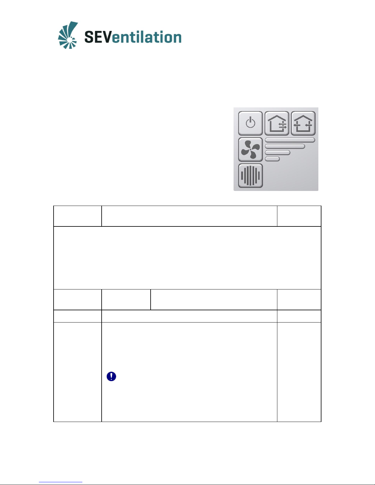
Determining the device type- The SEC-20-BF offers the possibility to connect different device
types of the SEVi series with different configurations. Depending on the device type, various
programmes are implemented in the software. They are described in the following.
To select them, the keys (4) “Alternating operation” and (2)
“Fan stage” are to be pressed simultaneously for ca.
5 seconds.
Then, the LED display (6) flashes (see Table).
To change the configuration, the key (2) “Fan stage” is
pressed to select another configuration (the corresponding
LEDs flash).
You can exit the selection mode by keeping the keys (4)
“Alternating operation” and (2) “Fan stage” pressed again
for ca. 5 seconds.
Configuration
Device type
Indicated by
LED
In the configurations 1 through 3, a difference is only made between air incoming side and
air discharge side!All four terminals can be allocated by the devices of the
SEVi 200/SEVi 160 series!
In the configurations 1 to 3, an allocation with the
SEVi 160DUO MINI is not possible!
1
SEVi 200 (DIBt)
SEVi 160– sound-optimized operation at
stage 1
1
2
SEVi 160 (DIBt)
2
3*
SEVi 160 air discharge
Stage 4 is designed as a pure air discharge solution in which
all fans connected are operated at the highest air discharge
stage (irrespective of the connection on the operator
control unit).
Note: Sufficient air must come in for pure air
discharge operation!
*Configuration 3: If stage 4 is activated, all fans connected are automatically
running (irrespective of their terminal assignment) in air discharge operation.
Intensive brief ventilation at stage 1-3 must be correspondingly set via (2)!
3
(4)
(2)
(6)
Page 13
13
In the configurations 4 to 7, attention must be paid additionally to the allocation of the top
and bottom terminal strips! The SEVi 160DUO MINI can only be operated
via the bottom terminal strip.
The configurations 4 to 7are designed for the common operation of the
devices of the SEVi 200/160 seriesand SEVi 160DUO MINI devices!
4
top
SEVi 160 – sound-optimized operation at stage 1
4
bottom
SEVi 160DUO MINI - Stage 4 is designed as a pure air
discharge solution in which the two fans are operated
at the highest air discharge stage (irrespective of the
connection on the operator control unit).
Note: Sufficient air must come in for pure air
discharge operation!
5
top
SEVi 160 (DIBt)
1 + 2
bottom
SEVi 160DUO MINI-Stage 4 is designed as a pure air
discharge solution in which the two fans are operated
at the highest air discharge stage (irrespective of the
connection on the operator control unit).
Note: Sufficient air must come in for pure air
discharge operationn!
6
top
SEVi 160 air discharge - Stage 4 is designed as a pure
air discharge solution in which all fans connected are
operated at the highest air discharge stage (irrespective
of the connection on the operator control unit).
Note: Sufficient air must come in for pure air
discharge operation!
1 + 2 + 3
bottom
SEVi 160DUO MINI- Stage 4 is designed as a pure air
discharge solution in which the two fans are operated
at the highest air discharge stage (irrespective of the
connection on the operator control unit).
Note: Sufficient air must come in for pure air
discharge operation!
7
top
SEVi 160 (DIBt)
1 + 2 + 3 + 4
bottom
SEVi 160DUO MINI 4-stage HRS operation
Page 14
14
3.8 Activating/changing the humidity feature
The SEC-20-BF central control unit can be operated optionally with or without humidity
control.
The humidity control distinguishes between five different conditions:
Condition
Indication via LED in the setting mode
Humidity threshold
(RH%)
Humidity control
off
All LEDs off
-
1
LED fan stage 1 flashes
50
2
LED fan stage 2 flashes
55
3
LED fan stage 3 flashes
60
4
LED fan stage 4 flashes
70
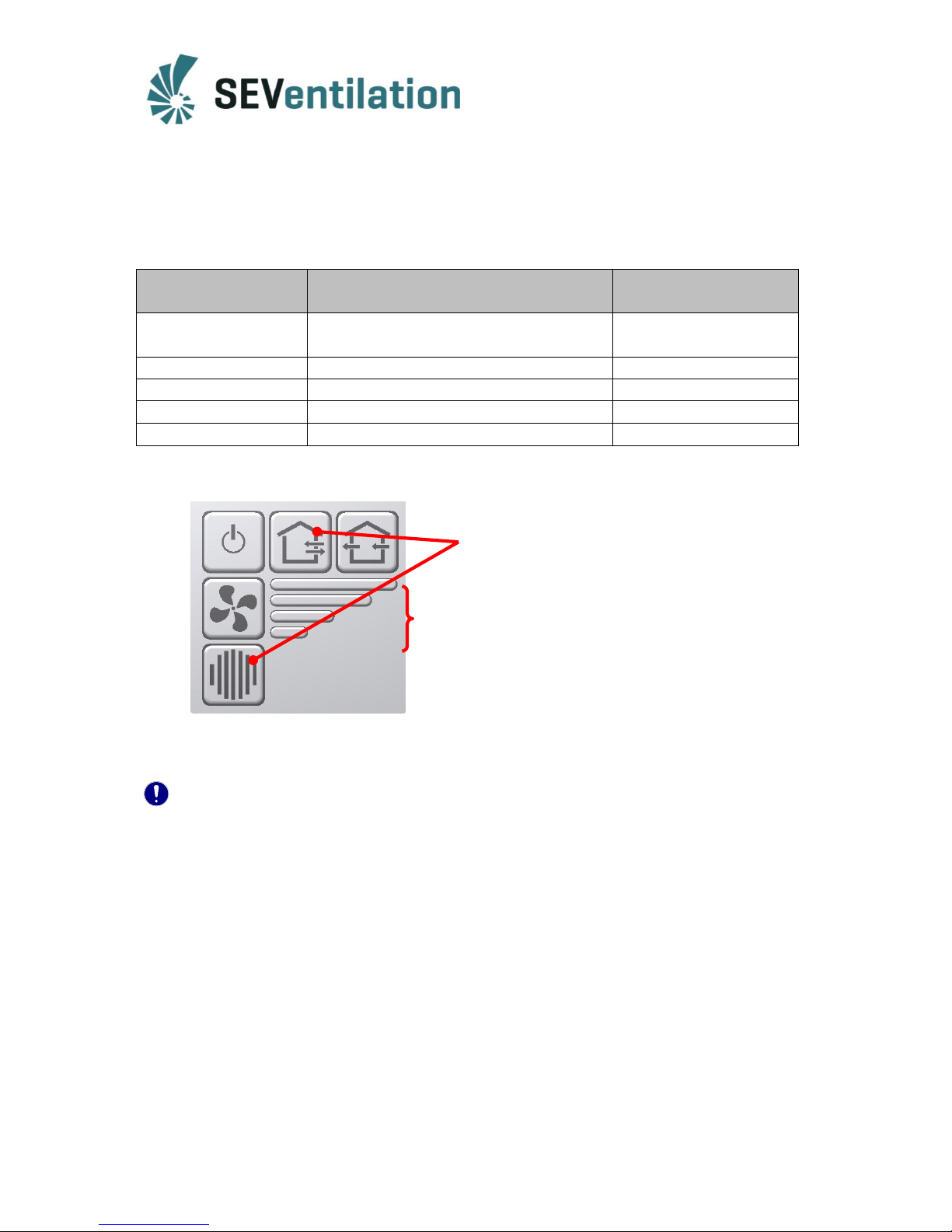
To activate the humidity control or to set another humidity threshold, the following steps are
to be taken:
Keep the keys “Alternating operation”and “Filter
change” pressed for 5 seconds. The control changes to
the activate/deactivate mode.
The condition currently set is indicated by the LED of
the fan stages (see table).
The desired condition of the humidity control can be
selected by pressing the key “Fan stage”.
Press the keys “Alternating operation” and “Filter change” anew for at least 5 seconds to save
the setting selected. Then, the control unit returns again to normal operation.
Noteto humidity control:
In the activated mode of the humidity control, the room humidity is continuously measured.
If the value which has been set for the humidity threshold is exceeded, the fan stage of the
fans connected is increased by one stage until fan stage 4 is reached. The stages are gradually
increased at 15-minute intervals.
If the value measured is lower than the humidity threshold set (minus a hysteresis of about
5%), the fan stage is decreased gradually again down to stage 1.
The manual change of the fan stage is still possible. However, the manual setting will be
corrected at 15-minute intervals if the humidity control is switched on.
Delivery status: configuration 1, humidity control off
Page 15
15
3.9 Combination with surface-mounted housing(optionally available)
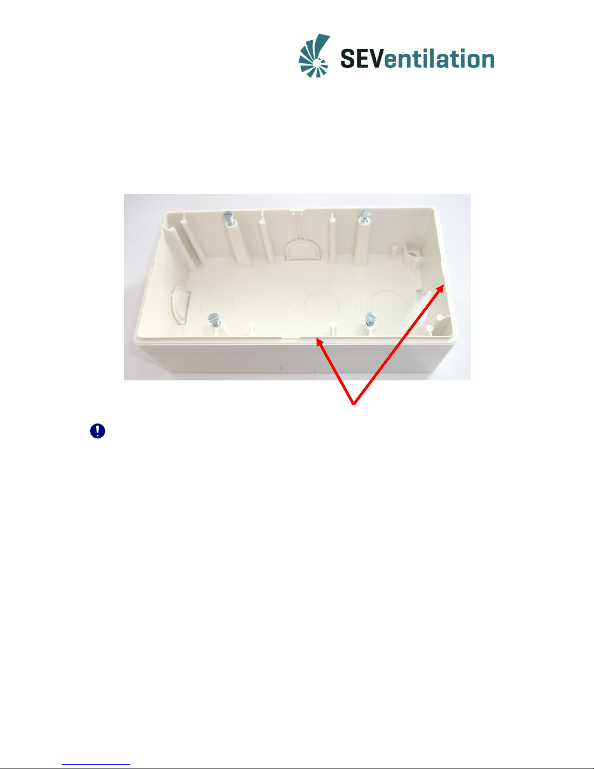
If a surface-mounted solution is selected for the control unit installation, the surfacemounted housing supplied as accessory can be used.
In order to ensure that the double frame fits, only the circumferential strip must be removed.
Important!
The surface-mounted housing must be provided with a separating element in the centre to
ensure the proper functioning of the humidity analysis!
Afterwards, the four screws can be used for fixing the lower part on the surface-mounted
housing.
Page 16

16
EC Declaration of Conformity
The company
SEVentilation GmbH
E.-Thälmann-Str. 12-14
07768 Kahla
Germany
declares under its sole responsibility that the products:
of type: SEVi 200 / SEVi 200U / SEVi 200L /SEVi 160 / SEVi 160DUO / SEVi 160U / SEVi 160DUO MINI / SEVi
160U / SEVi 160L / SEVi 160R / SEVi 160CE / SEVi 160RO / SEVi 160ALD / A160
(decentral ventilation devices with and without heat recovery),
to which this declaration refers, comply with the following standards and normative documents:
EN 55014 -1; 2006
EN 55014 -2; 1997, +A1; 2001
EN 61000-6-1, 2007; Generic Standards EMC – Immunity
EN 61000-6-3, 2007; Generic Standards EMC – Emission Standard
EN 61000-3-2, 12.2001; Low-Frequency System Perturbation
EN 61000-3-3, 1.1998
EN 60335-1, EN 60335-2-65; (safety of household and similar electrical appliances)
according to the provisions in the Directive 2004/108/EC or (EMC 2008), the Directive 2006/95/EC (Low Voltage
Directive) and the RoHS Directive 2002/95/EC.
The decentral ventilation systems: “SEVi 200 / SEVi 200U / SEVi 200L /SEVi 160 / SEVi 160DUO /
SEVi 160DUO MINI / SEVi 160U / SEVi 160L / SEVi 160R / SEVi 160CE / SEVi 160RO / SEVi 160ALD / A160” with
and without heat recovery are used for the ventilation of apartments/accommodation units.
Kahla, 10/12/2015
Dipl.Wirt.Ing. (FH)* Nico Schellenberg
*Graduate Industrial Engineer
Page 17
17
The manufacturer reserves the right to change technical details!
Production:
SEVentilation GmbH
E.-Thälmann-Str. 12
07768 Kahla
Germany
Telephone: +49 36424 767472 Fax: +49 36424 767471 Email: [email protected]
 Loading...