

Page 1
Page 2
Document History
_____________________________________________________________________________________
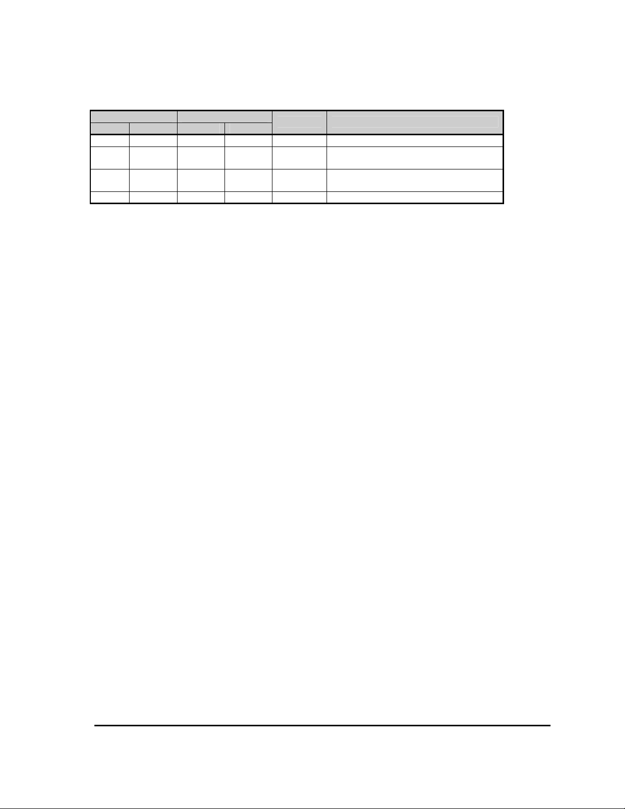
Document History
Author Reviewer
Initials Date Initials Date
PB 10/08/01 00.01 Original.
PR 16/11/01 0.50.00(A)
DC 23/04/04 0.50.00 (B)
DC 07/11/05 0.50.00(C) Clarified Digital I/O configuration table
Version Reason for Modification
Updated the Fault list, calibrator map and
added personalities.
Added omitted Flash Faults and seat
functionality description.
MillipaK PUMP Controller Manual Page 2 07/11/05
Page 3

Contents
_____________________________________________________________________________________
CONTENTS
INTRODUCTION .........................................................................................................................................................5
SAFETY .........................................................................................................................................................................6
INSTALLATION...........................................................................................................................................................7
MOUNTING ...................................................................................................................................................................7
MILLIPAK PUMP POWER WIRING.................................................................................................................................8
MILLIPAK PUMP LIGHT WIRING...................................................................................................................................9
CALIBRATOR ............................................................................................................................................................10
CALIBRATOR SECURITY LEVELS ................................................................................................................................11
NAVIGATION ..............................................................................................................................................................12
ADJUSTMENTS............................................................................................................................................................13
STATUS AND TEST INFORMATION...............................................................................................................................14
CONFIGURATION ....................................................................................................................................................15
SYSTEM CONFIGURATION...........................................................................................................................................15
System Voltage.......................................................................................................................................................16
System I/O Configuration ......................................................................................................................................17
Analogue Functions ...............................................................................................................................................18
Accelerator Full /Zero Setting ...............................................................................................................................20
PERFORMANCE ...........................................................................................................................................................21
Lift and Power Steer Ramps ..................................................................................................................................21
Creep Speed...........................................................................................................................................................22
Maximum Speed.....................................................................................................................................................23
FEATURES..................................................................................................................................................................24
STANDARD CONTROLLER FEATURES..........................................................................................................................24
Lift Switch Inputs - Priority ...................................................................................................................................25
Lift Switch Inputs - Additive ..................................................................................................................................26
Compensation ........................................................................................................................................................27
Seat Switch............................................................................................................................................................. 28
Power Steer Input ..................................................................................................................................................29
Lift Inhibit Input.....................................................................................................................................................30
Cooling Fan...........................................................................................................................................................31
Pump Hours Meter ................................................................................................................................................32
Personality Checksum ...........................................................................................................................................33
System State ...........................................................................................................................................................33
SAFETY FEATURES .....................................................................................................................................................34
Fail-safe.................................................................................................................................................................34
CONTROLLER PROTECTION FEATURES .......................................................................................................................35
Temperature Monitoring .......................................................................................................................................35
Maximum Temperature Logging ...........................................................................................................................35
Timed Current Cutback .........................................................................................................................................36
Safe Operating Area (SOA) ...................................................................................................................................37
Under-voltage protection.......................................................................................................................................38
COMMISSIONING CHECKLIST ............................................................................................................................40
PERSONALITY RECORD...............................................................................................................................................41
FAULT FINDING .......................................................................................................................................................42
FAULT CLEARANCE....................................................................................................................................................43
USING STATUS AND TEST MENUS ..............................................................................................................................43
FAULT REPORTING FORM...........................................................................................................................................45
MillipaK PUMP Controller Manual Page 3 07/11/05
Page 4

Contents
_____________________________________________________________________________________
SOFTWARE VERSION AND SERIAL NUMBER INDICATION............................................................................................46
SPECIFICATIONS .....................................................................................................................................................47
POWER CONFIGURATIONS ..........................................................................................................................................47
EMC STANDARDS.......................................................................................................................................................47
SOCKET B PROTECTION ..............................................................................................................................................47
CONTACTOR DRIVE RATINGS......................................................................................................................................47
ANALOGUE INPUT IMPEDANCE...................................................................................................................................47
DIGITAL INPUT IMPEDANCE........................................................................................................................................47
EMC GUIDELINES....................................................................................................................................................48
ORDERING INFORMATION...................................................................................................................................49
MillipaK PUMP Controller Manual Page 4 07/11/05
Page 5

Introduction
_____________________________________________________________________________________
Introduction
The MillipaK PUMP (series motor) range of controllers provides a new range of power frames for
24V-48V, 180A - 600A in one of two small, highly efficient packages. This is achieved using a
Sevcon patented power switching scheme and radical new construction techniques, which enable
large powers to be incorporated into very small packages.
The MillipaK provides a completely sealed (IP66) unit containing both power and logic circuitry,
as well as all suppression components.
MillipaK supports Sevcon’s existing MOS90 calibrator for adjustment of pump characteristics.
Controllers are FLASH microprocessor based enabling field re-programming for new features and
have numerous user set-up options. The MillipaK uses high frequency (silent) MOSFET power
switching technology, to control a Series power frame comprising Armature circuit only.
Armature currents are monitored. Controllers have been designed to satisfy the requirements of
the relevant UL and EC standards.
MillipaK PUMP Controller Manual Page 5 07/11/05
Page 6

Safety
_____________________________________________________________________________________
Safety
The MillipaK controller contains a triple fail-safe system to give a high level of safety. If the
diagnostic LED is not illuminated or flashes, the safety circuit may have tripped and the truck
may not drive.
The MillipaK controller may be used with suitable onboard chargers, as supplied by Sevcon.
MillipaK PUMP Controller Manual Page 6 07/11/05
Page 7
Installation Mounting
_____________________________________________________________________________________
Installation
The small footprint of the MillipaK controller gives maximum flexibility to the user for mounting
options. The following section gives details of certain criteria that should be considered when
situating the controller on a vehicle.
Mounting
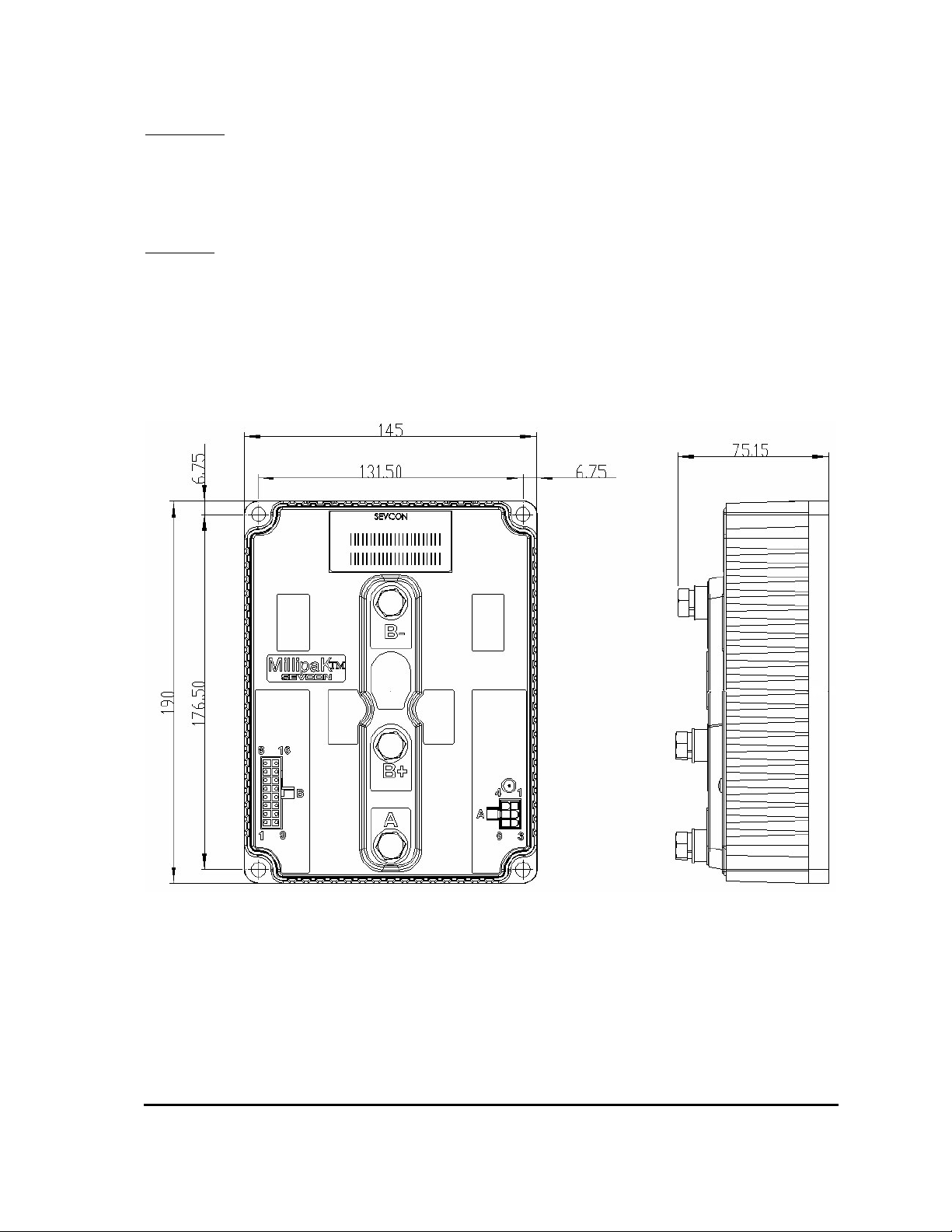
The MillipaK and MillipaK HP units provide 4 x M6 clearance holes for mounting. The
controllers should be mounted onto a metal base plate, as large as possible to provide heatsinking. The surface finish should be flat, clean and burr free and thermal compound should be
applied to the controller base before fitting.
MillipaK HP Controller Dimensions
Maximum terminal torque: M8 terminals – 10NM
M6 terminals – 7NM
MillipaK PUMP Controller Manual Page 7 07/11/05
Page 8
Installation Wiring/Power
_____________________________________________________________________________________
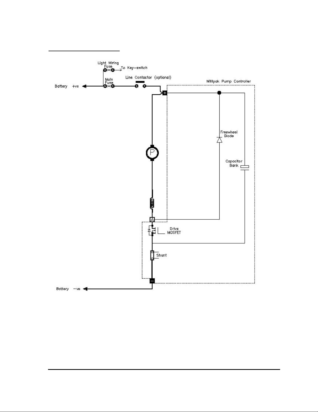
MillipaK Pump Power Wiring
NOTE: The Pump battery positive power terminal may be wired directly to the battery positive
(via a suitable fuse) or via a line contactor if used in a Traction / Pump system.
It should be considered whether or not pump operation is required if a traction fault causes the
line contactor to drop out.
MillipaK PUMP Controller Manual Page 8 07/11/05
Page 9
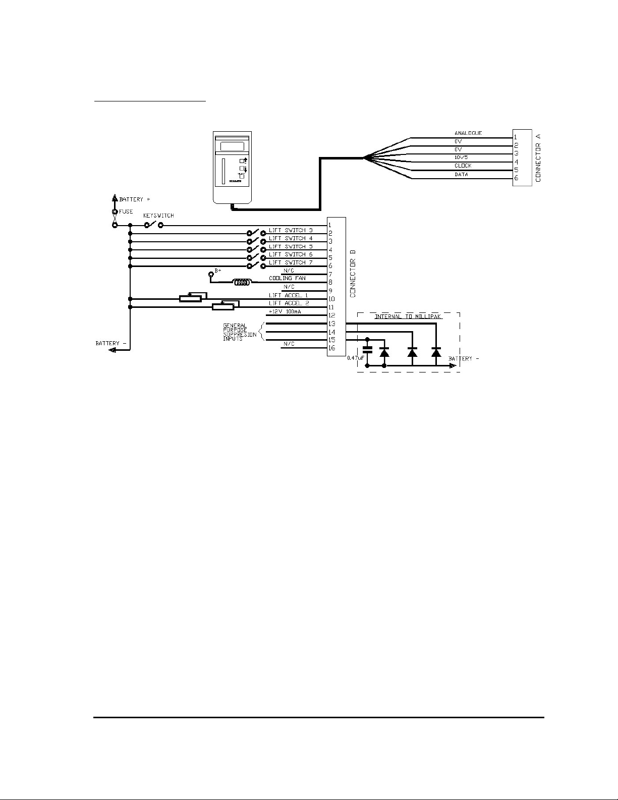
Installation Wiring/Light
______________________________________________________________________________
MillipaK Pump Light Wiring
NOTES:
The line and auxiliary contactors coils are wired to B+, on the switched side of the key-switch.
The second analogue input on pin 11 is also available for use as a digital input. See system
configuration section for how to configure the second analogue input as a digital switch input.
Pin 12 on the Core and Standard HP variants is available for 100mA supply, typically used for
(but not limited to) accelerator modules.
Pins 13,14 & 15 are general-purpose suppression connections and may be used to suppress spikes
generated by contactors opening / closing. The internal configuration is shown below:
Pin 16 on the Core and Standard HP variants is used to select FLASH memory program update
mode and should normally be left unconnected.
MillipaK PUMP Controller Manual Page 9 07/11/05
Page 10
Calibrator Calibrator/General
______________________________________________________________________________
Calibrator
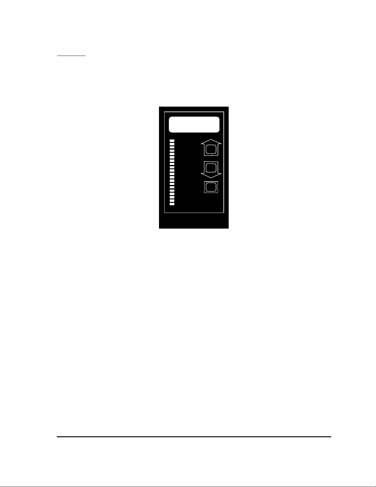
The Calibrator is a hand-held adjustment unit which can be used to configure and test the system.
The MillipaK is designed to work with the Calibrator currently in use with SEVCON's MOS90
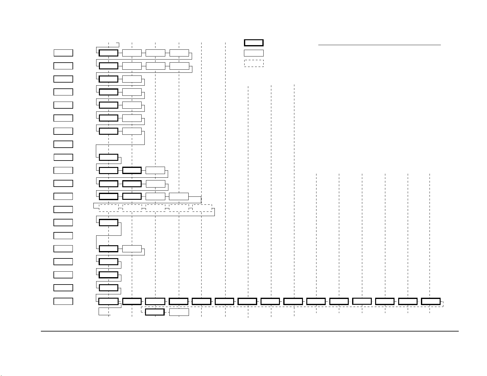
system. See diagram below. The menu structure is shown in the Calibrator Map located near the
end of this manual.
1.8.8.8
+
-
SELECT
CAL IBRA TOR
Sevco ntr ol
MillipaK PUMP Controller Manual Page 10 07/11/05
Page 11
Calibrator Calibrator/Security Levels
______________________________________________________________________________
Calibrator Security Levels
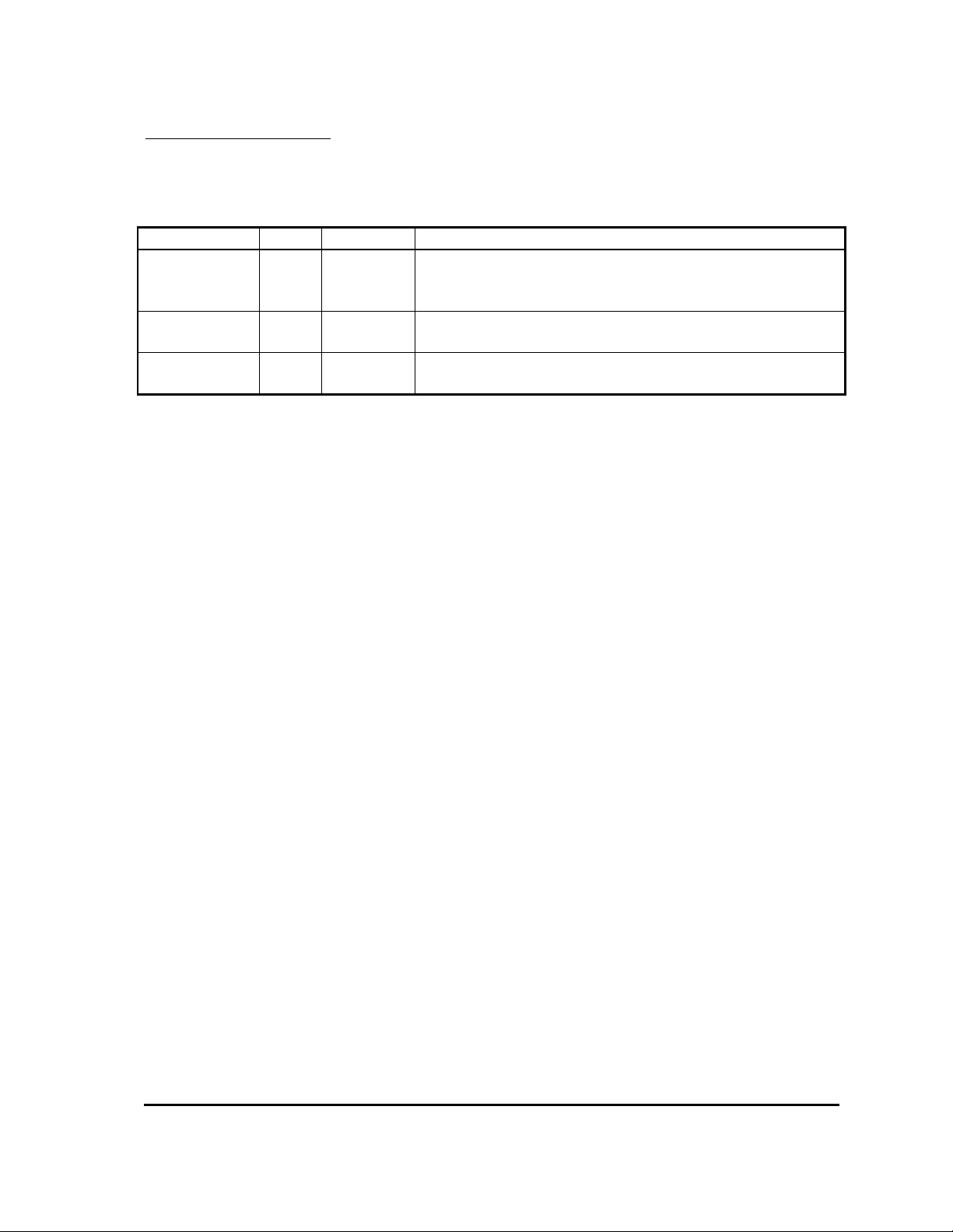
Which personalities and status items which can be viewed on the Calibrator is restricted using
passwords. There are three levels of Calibrator access. These are shown in the table below:
Access Level Text Password Description
Default. This level is selected when no password or an
Service Ser -
invalid password is entered. Only items shown in the
Calibrator Map with a thick solid border are displayed.
Engineering Eng 1645
All Adjust All
Contact
SEVCON
Only items shown in the Calibrator Map with a thick or
thin solid border are displayed.
All items are displayed.
Note, in Service or Engineering mode, only items appropriate to the current system configuration
are displayed. For example, if lift switch 5 is not configured, then the Speed personality will not
be displayed for that switch. In All Adjust mode, all items are shown regardless of configuration.
The password can only be entered just after power up when the Pump Hours Counter is displayed.
The '+' and '-' buttons are used to enter the password. The first digit is entered by pressing the '+'
button the appropriate number of times (i.e. once to enter 1). The second digit is entered by
pressing the '-' button the appropriate number of times (i.e. 6 times to enter 6). The third digit is
entered using the '+' button again and the final digit is entered using the '-' button again. Note that
when the '+' or '-' buttons are pressed, the display still changes to show hours or 1000 x hours.
When the password has been completely entered press either the '+' button or the SELECT button
to initiate verification. If the password has been entered correctly, the text shown in the table
above appropriate to the required level will be displayed for 1s indicating the password was
accepted. If the password was incorrect or no password was entered, the system always defaults to
Service mode.
After the Security Level has been displayed, the system enters the normal menu structure shown
in the Calibrator Map. To change the password level, you need to recycle the Keyswitch.
MillipaK PUMP Controller Manual Page 11 07/11/05
Page 12

Calibrator Calibrator/Navigation
______________________________________________________________________________
Navigation
The Calibrator uses all three buttons for navigating through the menu structure.
Use the SELECT button to move through the menu structure. When the SELECT button is
pressed the next menu item is displayed. The default direction is from left to right, top to bottom.
If the '+' and '-' buttons are held down together, the ID of the currently displayed menu item is
shown. For example, if the Current Limit personality was selected, then the ID would be 0.01
(menu 0, item 1). This allows the operator to locate where they are in the map.
If the '+' and '-' buttons are held down together for more than 3 seconds, the direction through the
menu structure is reversed. Now when the SELECT button is pressed the direction is from right to
left, bottom to top. In this mode, the LED on the Calibrator will flash. If the '+' and '-' buttons are
held down together for more than 3 seconds again, the direction reverts back to the first direction
and the Calibrator LED stops flashing.
The SELECT button is used to navigate through most of the menu structure, however, the Test
menu (menu 19) is slightly different. Pressing the SELECT button will take you to the first item
in the Test menu, (item 19.01 - Accelerator Demand). To navigate the Test menu, you need to use
the '+' and '-' buttons. The '+' button moves up the Test menu and the '-' button moves back down.
Pressing the SELECT button at any time exits the Test menu and moves to the first item in the
menu structure (menu item 0.01 – Lift Speed 1).
The items which are displayed depends on the current system configuration and the Security
Level.
MillipaK PUMP Controller Manual Page 12 07/11/05
Page 13

Calibrator Calibrator/Adjustments
______________________________________________________________________________
Adjustments
Menus 0 to 12 are primarily used for configuring the system. All the personalities that the system
uses to configure each function are in one of these menus. A brief description of the purpose of
each menu is listed below. For more complete descriptions of each personality refer to the
appropriate section in this manual.
Menu Name Purpose
0 Speed 1 Used to set pump speed for lift accelerator 1.
1 Speed 2 Used to set pump speed for lift accelerator 2.
2 Speed 3 Used to set pump speed for switch input 3.
3 Speed 4 Used to set pump speed for switch input 4.
4 Speed 5 Used to set pump speed for switch input 5.
5 Speed 6 Used to set pump speed for switch input 6.
6 Speed 7 Used to set pump speed for switch input 7.
7 Unused Unused.
8 Creep Speed Used to set creep speed.
9 Ramps Used to set lift and power steer ramp times.
10 Power Steer Used to set-up power steer function.
11 Current Limit
Used to set motor current limit, seat delay and low voltage start
and cut levels.
Used to configure the system at a high level. Items to configure
the system I/O and performance are located in here. It is
12 System Set-up
recommended that items in this menu are configured first before
any of the other personalities. Unlike the personalities in the
other menus, changes to items in this menu do not take affect
until the Keyswitch is recycled.
MillipaK PUMP Controller Manual Page 13 07/11/05
Page 14

Calibrator Calibrator/Status and Test Information
______________________________________________________________________________
Status and Test Information
Menus 13 to 19 are primarily used for providing information about the system. Every parameter
which the system measures in located in one of these menus. A brief description of the purpose of
each menu is listed below.
Menu Name Purpose
If there is a fault active in the system, this menu provides
13 System Status
information about what the fault is. Refer to the Diagnostics
section for more information.
14 - Reserved for future use.
Used to display Battery and Capacitor Voltage measurements.
The Battery Voltage measurement shows the voltage measured
15 System Voltages
at the Keyswitch pin (pin 1 on connector B). The Capacitor
Voltage measurement shows the voltage measured at the B+
terminal.
16 Motor Voltages Used to show the voltage measured at the Point A terminal.
17 Motor Current Used to show the PUMP motor current Measurement.
Used to access the Heatsink Temperature measurement and the
Maximum Heatsink Temperature log. Refer to the Temperature
Monitoring section.
18
Heatsink
Temperature
Used to access items which allow for testing of all the Analogue
and Digital inputs available on connector B. Also displays unit
19 Test Menu
information such as the Software Version, Controller Serial
Number and the Personality Checksum. Refer to the appropriate
sections for more information on each of these items.
MillipaK PUMP Controller Manual Page 14 07/11/05
Page 15

Configuration System
______________________________________________________________________________
Configuration
Configuration of the MillipaK controller is split into two categories – system and performance,
which will be discussed in turn.
System Configuration
The MillipaK system configuration items relate to how the MillipaK will interface with connected
hardware such as the system battery, lift control switches, accelerator and the pump motor.
MillipaK PUMP Controller Manual Page 15 07/11/05
Page 16
Configuration System/Voltage
______________________________________________________________________________
System Voltage
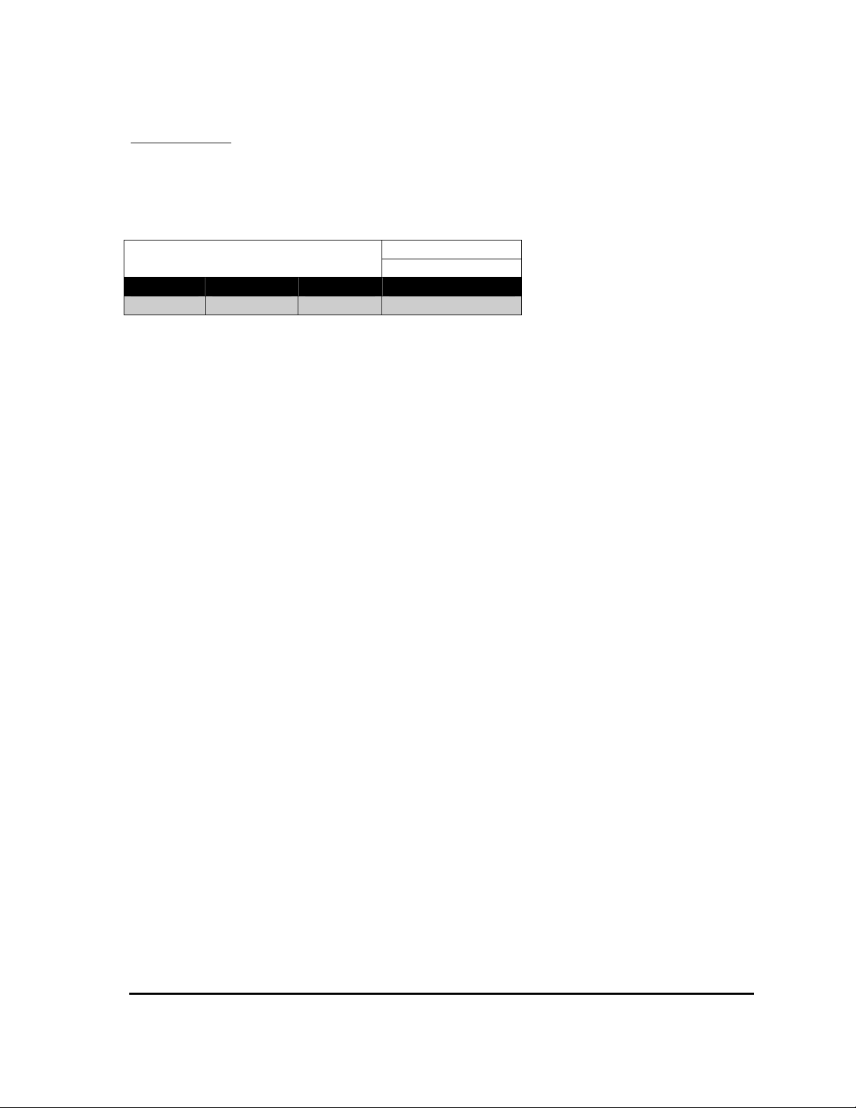
The system voltage usually refers to the main system supply battery voltage. The controller uses
this information to ensure low and high voltage settings are within an appropriate range.
Power Up System Voltage
Calibrator Menu Reference:
12.05
Minimum Maximum Step Size Default
24v 48v 2v 24v
MillipaK PUMP Controller Manual Page 16 07/11/05
Page 17
Configuration System/IO Configuration
______________________________________________________________________________
System I/O Configuration
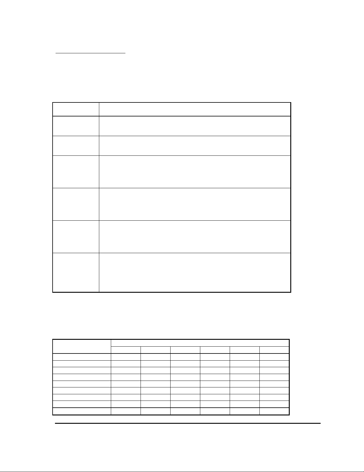
The digital inputs, analogue inputs and contactor drive outputs available on socket B can be
configured in a number of ways to suit various applications. The table below shows a range of
pre-determined settings which are available to the user and should cover the majority of
applications, see below:
Digital I/O
Value
1 Normal switch inputs are used for lift switches. Lift Inhibit is available via the last
switch input on the MillipaK Core or via the second analogue input on the
MillipaK HP.
2 Normal switch inputs are used for lift switches. Power Steer Trigger is available
via the last switch input on the MillipaK Core or via the second analogue input on
the MillipaK HP.
3 4 of the normal switch inputs are used for lift switches. Power Steer Trigger is
available on a normal switch input. Lift Inhibit is available via the last switch
input on the MillipaK Core or via the second analogue input on the MillipaK HP.
Lift Switch 5 is dropped to leave 2 switches with compensation and 2 additive
switches.
4 4 of the normal switch inputs are used for lift switches. Lift Inhibit is available on
a normal switch input. Power Steer Trigger is available via the last switch input on
the MillipaK Core or via the second analogue input on the MillipaK HP. Lift
Switch 5 is dropped to leave 2 switches with compensation and 2 additive
switches.
5 3 of the normal switch inputs are used for lift switches. Lift Inhibit and Power
Steer Trigger are available on normal switch inputs. Lift Switch 4 is available via
the last switch input on the MillipaK Core or via the second analogue input on the
MillipaK HP. Lift Switch 5 is dropped to leave 2 switches with compensation and
2 additive switches.
6 2 of the normal switch inputs are used for lift switches. Lift Inhibit, Power Steer
Trigger and Seat Switch are available on normal switch inputs. Lift Switch 4 is
available via the last switch input on the MillipaK Core or via the second analogue
input on the MillipaK HP. Lift Switches 5 and 7 are dropped to leave 2 switches
with compensation and 1 additive switches. There is one contactor drive, the
Cooling Fan Drive.
Description
If your application doesn’t fit any of the above, please contact Sevcon with details of your
requirements.
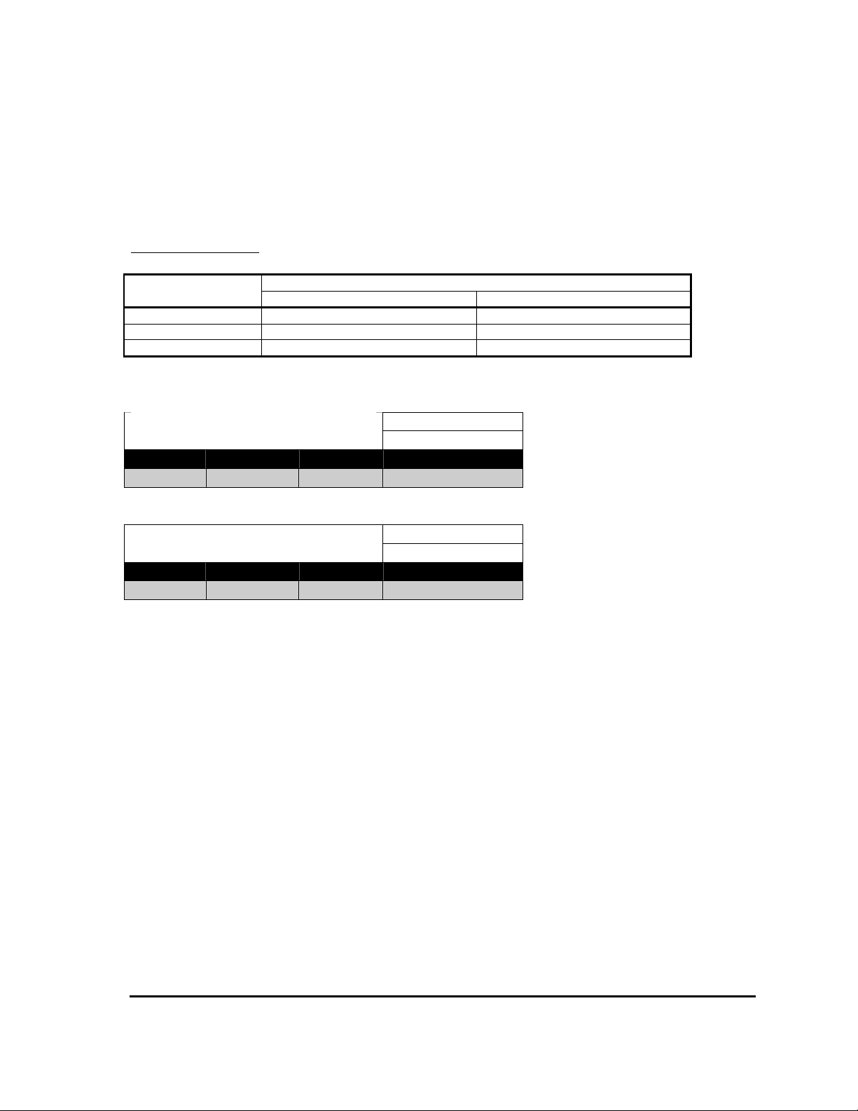
Each of the above configurations allocates the controller i/o as shown below:
Digital
Function 1 2 3 4 5 6
Lift Switch 3 B2 B2 B2 B2 B2 B2
Lift Switch 4 B3 B3 B3 B3 B3 B3
Lift Switch 5 B4 B4
Lift Switch 6 B5 B5 B5 B5 AD AD
Lift Switch 7 B6 B6 B6 B6 B6
Lift Inhibit AD AD B4 B4 B4
Power Steer Trigger AD B4 AD B5 B5
Seat Switch B6
Cooling Fan Drive B8
Value of Digital I/O Configuration Item
MillipaK PUMP Controller Manual Page 17 07/11/05
Page 18
Configuration System/IO Configuration
______________________________________________________________________________
Notes:
1. Dx refers to Digital Switch input x.
2. Cx refers to Contactor Drive output x.
3. If the Analogue Input 2 is set to Digital, switch input D6 is read from the Analogue input and
not the switch input.
Analogue Functions
Analogue
Function 1 2
Lift Accelerator 1 Ana.1 (B10) Ana.1 (B10)
Lift Accelerator 2 Ana.2 (B11)
Digital Ana.2 (B11)
Value of Analogue Input Configuration Item
Power Up Digital Configuration
Calibrator Menu Reference:
12.02
Minimum Maximum Step Size Default
1 6 1
Power Up Analogue Configuration
Calibrator Menu Reference:
12.03
Minimum Maximum Step Size Default
1 2 1
MillipaK PUMP Controller Manual Page 18 07/11/05
Page 19
Configuration System/Motor Set-up
_____________________________________________________________________________________
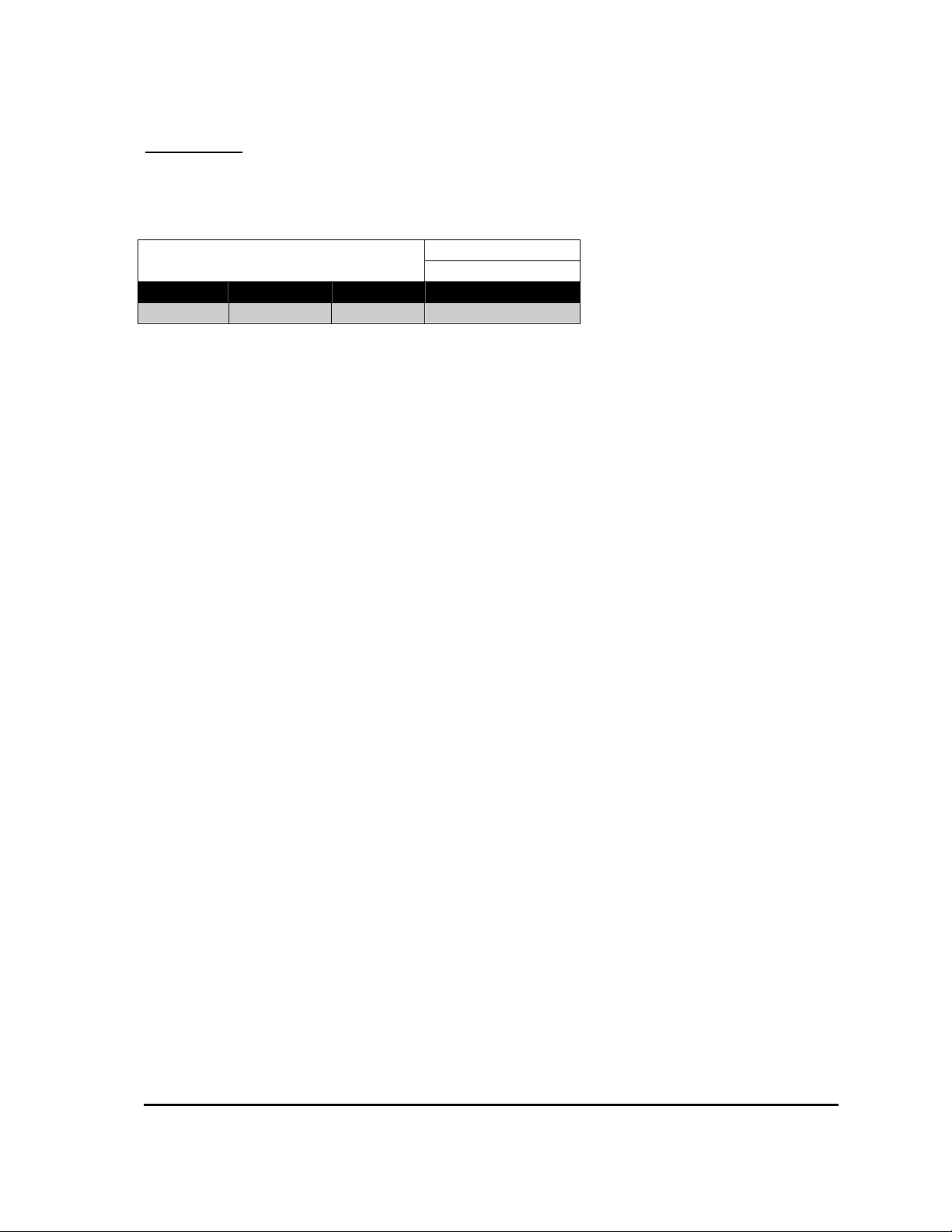
Current Limit
The current limit personality is provided to allow the user to limit the maximum current supplied
to the motor to a value lower than the peak rating of the controller.
Immediate Current Limit
Calibrator Menu Reference:
0.01
Minimum Maximum Step Size Typical Value
50A CBR 10A CBR
Where CBR is Controller Block Rating.
MillipaK PUMP Controller Manual Page 19 07/11/05
Page 20
Configuration System/Accelerator
______________________________________________________________________________
Accelerator Full /Zero Setting
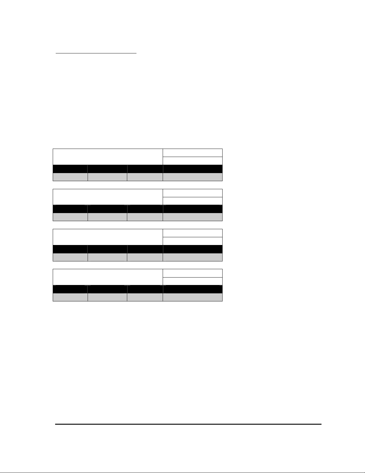
The lift accelerator/analogue inputs are flexible in the range of signal sources they can
accommodate and can be adjusted to minimise dead-bands and mechanical tolerances. Each
analogue input has 2 adjustments associated with it to allow the input voltage range to be
determined.
The 2 adjustments are called the “Accelerator Zero Level” and the “Accelerator Full Level”. If
these were set to 0.20V and 4.80V then 0% demand would start at 0.20V at the input, increasing
to 100% demand at 4.80V. For accelerators with decreasing voltage outputs, the Zero adjustment
might be set to 3.5V and the Full adjustment to 0.0V. The Calibrator test menu shows the
instantaneous voltage reading, and the equivalent % “push” for each input.
Immediate Accelerator 1 Zero Volts
Calibrator Menu Reference:
0.03
Minimum Maximum Step Size Typical Value
0.00V 4.50V 0.02V 0.20V
Immediate Accelerator 1 Full Volts
Calibrator Menu Reference:
0.04
Minimum Maximum Step Size Typical Value
0.00V 4.50V 0.02V 3.50V
Immediate Accelerator 2 Zero Volts
Calibrator Menu Reference:
1.03
Minimum Maximum Step Size Typical Value
0.00V 4.50V 0.02V 0.20V
Immediate Accelerator 2Full Volts
Calibrator Menu Reference:
1.04
Minimum Maximum Step Size Typical Value
0.00V 4.50V 0.02V 3.50V
The PWM demand will vary between the Creep level and Maximum Speed for that lift accelerator
as the accelerator voltage varies between “Accelerator Zero” and “Accelerator Full”.
MillipaK PUMP Controller Manual Page 20 07/11/05
Page 21
Configuration Performance/Ramp Up
______________________________________________________________________________
Performance
Various parameters may be adjusted to tailor the performance of the vehicle to customer
requirements.
Lift and Power Steer Ramps
Theses are adjustable delays to ramp up the pulsing from 0% on to 100% on, and can be used to
ensure smooth start / stop.
Immediate Lift Ramp Up
Calibrator Menu Reference:
9.01
Minimum Maximum Step Size Typical Value
0.1S 5.0S 0.1S 1.5S
Immediate Power Steer Ramp Up
Calibrator Menu Reference:
9.02
Minimum Maximum Step Size Typical Value
0.1S 5.0S 0.1S 1.5S
Immediate Ramp Down
Calibrator Menu Reference:
9.03
Minimum Maximum Step Size Typical Value
0.1S 0.5S 0.1S 0.1S
MillipaK PUMP Controller Manual Page 21 07/11/05
Page 22
Configuration Performance/Creep Speed
______________________________________________________________________________
Creep Speed
The Creep speed is adjustable and is used to select a minimum pulsing level as soon as any pump
function is requested, to minimise delays and dead-bands. The motor voltage is rapidly ramped to
the creep level (equivalent to a 100mS ramp time).
Immediate Creep Speed
Calibrator Menu Reference:
8.01
Minimum Maximum Step Size Typical Value
0% 25% 1% 0%
MillipaK PUMP Controller Manual Page 22 07/11/05
Page 23
Configuration Performance/Maximum Speed
______________________________________________________________________________
Maximum Speed
Adjustment limits the maximum applied %on to the motor. There are seven speed settings
available, one for each input (two analogue accelerators and 5 digital switches). These settings
can be used to set different pump motor speeds for the various vehicle functions.
Immediate Speed 1
Calibrator Menu Reference:
0.01
Minimum Maximum Step Size Typical Value
0% 100% 1% 100%
Immediate Speed 2
Calibrator Menu Reference:
1.01
Minimum Maximum Step Size Typical Value
0% 100% 1% 100%
Immediate Speed 3
Calibrator Menu Reference:
2.01
Minimum Maximum Step Size Typical Value
0% 100% 1% 100%
Immediate Speed 4
Calibrator Menu Reference:
3.01
Minimum Maximum Step Size Typical Value
0% 100% 1% 100%
Immediate Speed 5
Calibrator Menu Reference:
4.01
Minimum Maximum Step Size Typical Value
0% 100% 1% 100%
Immediate Speed 6
Calibrator Menu Reference:
5.01
Minimum Maximum Step Size Typical Value
0% 100% 1% 100%
Immediate Speed 7
Calibrator Menu Reference:
6.01
Minimum Maximum Step Size Typical Value
0% 100% 1% 100%
MillipaK PUMP Controller Manual Page 23 07/11/05
Page 24

Features Features
______________________________________________________________________________
Features
The MillipaK controller has several features designed to offer the user maximum flexibility,
safety and performance whilst ensuring the controller is protected against adverse or fault
conditions. These features can be split into three categories – standard controller features, safety
features and controller protection features.
Standard Controller Features
The following section details the standard features found on a MillipaK controller.
MillipaK PUMP Controller Manual Page 24 07/11/05
Page 25
Features Standard Features/Lift Switch Inputs - Priority
______________________________________________________________________________
Lift Switch Inputs - Priority
The two lift accelerators are normally referred to as inputs 1 & 2 and the digital switch inputs as 3
to 7. The priority assigned to each input is shown in the table below:
Priority Input Additional Comments
1(highest) Lift Accelerator 1
2 Lift Accelerator 2
3 Lift Switch 3
4 Lift Switch 4
5 Lift Switch 5
6 Lift Switch 6
7 Lift Switch 7
Lift Switches 5, 6 and 7 are lower priority than the other
Lift inputs only when they are configured as Priority.
Additive switches are handled separately. See next
section.
Assuming all the inputs are configured as priority, then even if more than one switch input (or
accelerator) is active only one demand will be used. This demand will be that of the highest
priority active input, even if this is the lowest demand. For this reason care must be taken in
setting accelerator zero levels to ensure zero demand when the accelerator is inactive.
Power Up Speed 5 Priority / Additive
Calibrator Menu Reference:
4.02
Options Default
Priority Additive Priority
Power Up Speed 6 Priority / Additive
Calibrator Menu Reference:
5.02
Options Default
Priority Additive Priority
Power Up Speed 7 Priority / Additive
Calibrator Menu Reference:
6.02
Options Default
Priority Additive Priority
For example, if switches 5 – 7 are set as priority then activating all switches will result in the
speed demand set for switch 5 being used.
MillipaK PUMP Controller Manual Page 25 07/11/05
Page 26

Features Standard Features/Lift Switch Inputs - Additive
______________________________________________________________________________
Lift Switch Inputs - Additive
Lift input switches 5 to 7 may be configured as Additive. As the name implies if two or more
switches configured as additive are active together then the speed demand set for each switch will
be added together and this will be the final speed demand.
Additive also applies if a priority and an additive switch are active simultaneously.
For example if lift accelerator 1 input demand is at 20%, switch 3 is active with its maximum
speed personality set to 20% and switch 5 is active and programmed as additive and with a speed
setting of 30 % then the final demand would be 50% (lift accelerator 1 demand + switch 5
demand).
MillipaK PUMP Controller Manual Page 26 07/11/05
Page 27
Features Standard Features/Compensation
______________________________________________________________________________
Compensation
A compensation factor can be programmed for lift accelerators 1 and 2, lift switches 3 and 4, and
the power steer input (if configured).
The compensation factor is designed to help keep a constant lift speed or power steer assist level
under varying load conditions.
The compensation feature works by calculating how much extra motor voltage is needed to keep
the motor speed constant. The calculation uses the motor current and the relevant personality to
determine the extra motor voltage required.
To set the compensation factors for the lift accelerators or switches you should first set the desired
unloaded speed using the maximum speed personality for the lift input in question. The next step
should be to activate the lift under full load and increment the compensation personality until the
desired full load speed is achieved.
The following personalities may be programmed to provide compensation for the relevant inputs:
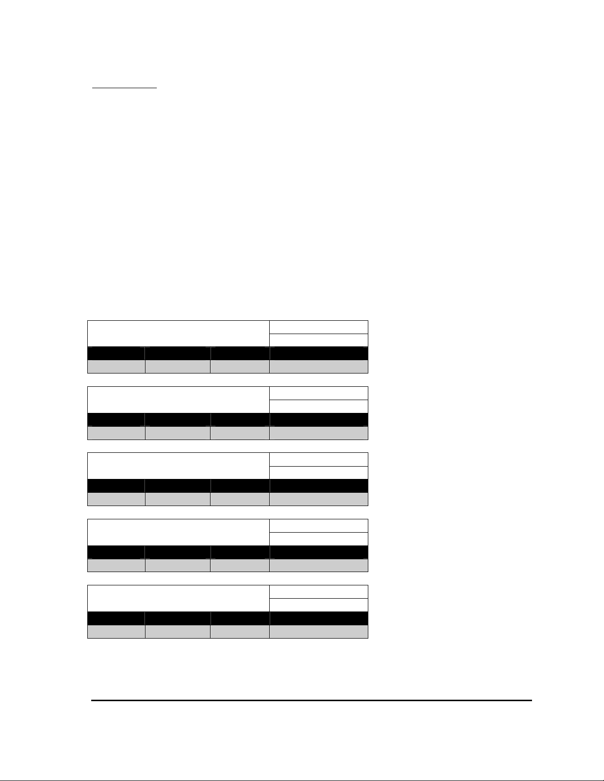
Immediate Compensation 1
Calibrator Menu Reference:
0.02
Minimum Maximum Step Size Default
0% 200% 1% 0%
Immediate Compensation 2
Calibrator Menu Reference:
1.02
Minimum Maximum Step Size Default
0% 200% 1% 0%
Immediate Compensation 3
Calibrator Menu Reference:
2.02
Minimum Maximum Step Size Default
0% 200% 1% 0%
Immediate Compensation 4
Calibrator Menu Reference:
3.02
Minimum Maximum Step Size Default
0% 200% 1% 0%
Immediate Power Steer Compensation
Calibrator Menu Reference:
10.03
Minimum Maximum Step Size Default
0% 200% 1% 0%
MillipaK PUMP Controller Manual Page 27 07/11/05
Page 28
Features Standard Features/Seat Switch
______________________________________________________________________________
Seat Switch
A seat switch can be configured via the digital I/O configuration. If setup menu option seat switch
cuts pump is configured to on, and the seat switch is opened, and the seat switch timer has timed
out the controller will stop pulsing and a seat fault will be indicated. Before pulsing can be
restarted the seat switch must be closed. The time period is programmed by means of the
Calibrator (Seat Switch Delay).
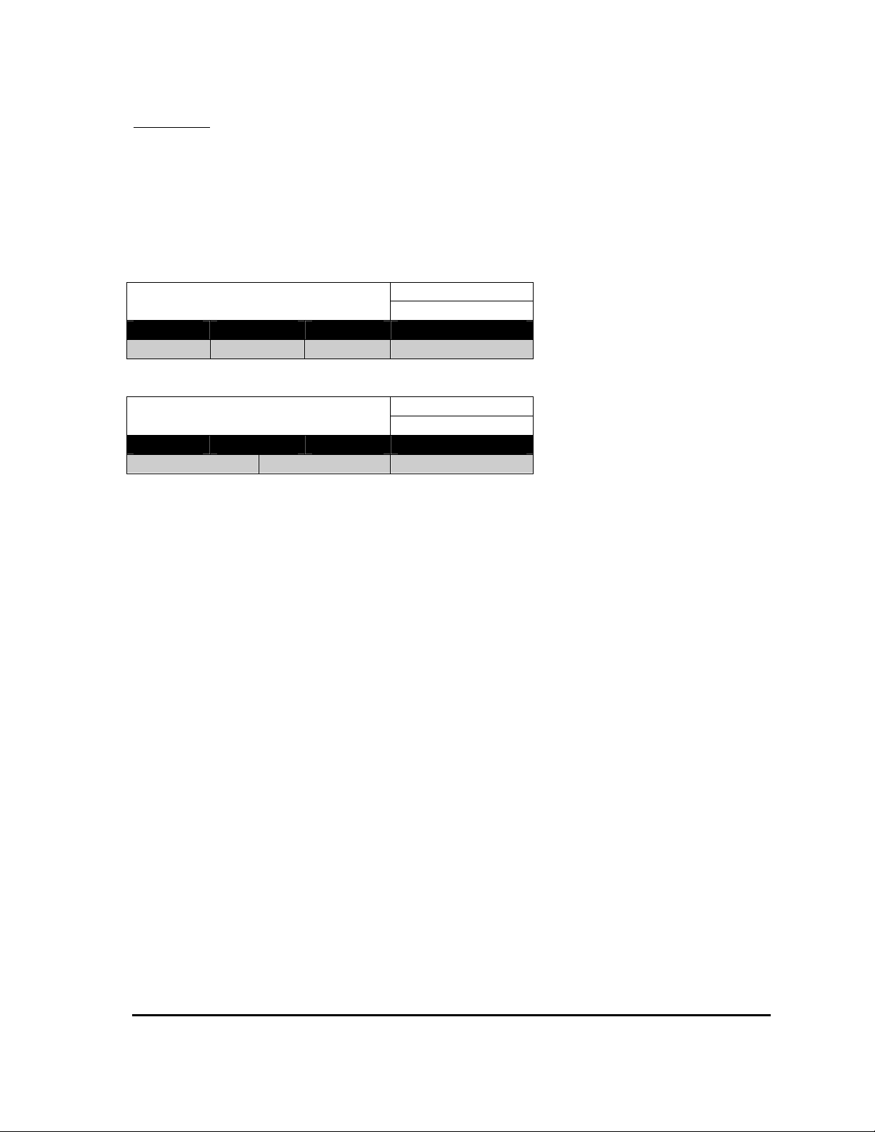
Immediate Seat Delay
Calibrator Menu Reference:
11.02
Minimum Maximum Step Size Typical Value
0.1S 5.0S 0.1S 5.0S
Power On Seat Cuts Pump
Calibrator Menu Reference:
12.04
Options Typical Value
OFF ON OFF
MillipaK PUMP Controller Manual Page 28 07/11/05
Page 29
Features Standard Features/Seat Switch
______________________________________________________________________________
Power Steer Input
Any one of the digital switch inputs may be configured as a Power Steer trigger. When configured
the power steer speed and delay may be programmed:
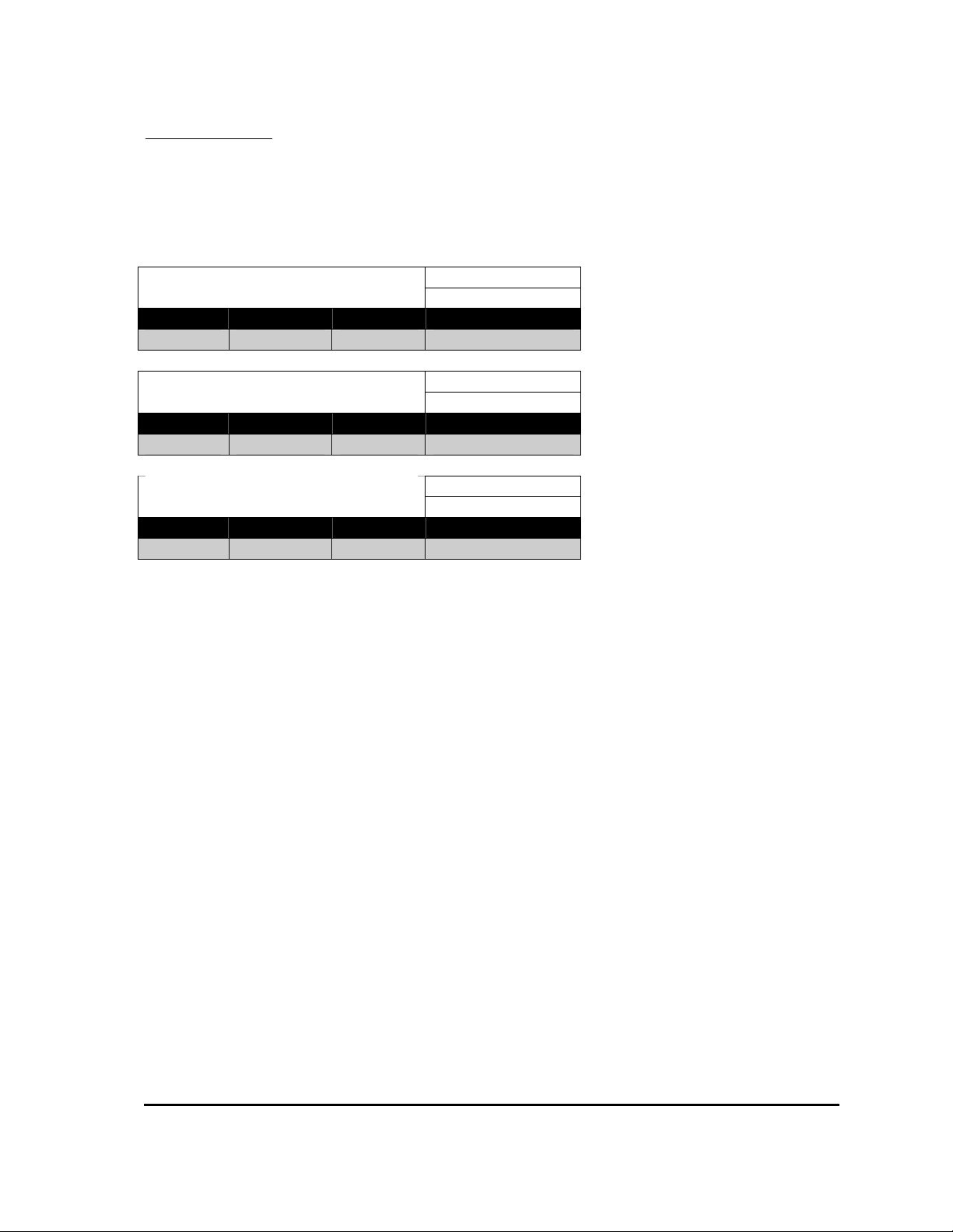
Power Steer Personalities:
Immediate Power Steer Speed
Calibrator Menu Reference:
10.01
Minimum Maximum Step Size Default
0% 100% 1% 100%
Immediate Power Steer Delay
Calibrator Menu Reference:
10.02
Minimum Maximum Step Size Default
0s 60s 1s 2S
Immediate Power Steer Compensation
Calibrator Menu Reference:
10.03
Minimum Maximum Step Size Default
0% 200% 1% 0%
The power steer delay is the length of time the demand will remain active after the trigger signal
is removed.
MillipaK PUMP Controller Manual Page 29 07/11/05
Page 30

Features Standard Features/Lift Inhibit Input
______________________________________________________________________________
Lift Inhibit Input
One of the digital inputs may be configured as Lift Inhibit. When the inhibit input is active then
no lift functions are allowed to start. Any lift functions already active will not be affected.
MillipaK PUMP Controller Manual Page 30 07/11/05
Page 31

Features Standard Features/Cooling Fan
______________________________________________________________________________
Cooling Fan
There is a facility provided on the standard MillipaK Pump controller which allows a traction
motor cooling fan to be activated via a contactor drive output. The output is activated when the
Seat Switch input is active. The seat switch input must be configured using the digital i/o
configuration item. The cooling fan drive is deactivated when the seat switch input is deactivated.
MillipaK PUMP Controller Manual Page 31 07/11/05
Page 32

Features Standard Features/Pump Hours Meter
______________________________________________________________________________
Pump Hours Meter
The MillipaK maintains a log of the number of hours during which the controller is providing
Pump functionality. The Pump Hours Meter runs whenever the pump motor speed is greater than
zero. The current number of logged Pump hours can be viewed using the Calibrator. Refer to the
Calibrator section for more information.
MillipaK PUMP Controller Manual Page 32 07/11/05
Page 33

Features Standard Features/Personality Checksum
______________________________________________________________________________
Personality Checksum
As you can see from this Manual and the Calibrator Map, the MillipaK employs quite a few
personalities to give the user as much flexibility as possible in setting up their system. After the
personalities have been setup to give the desired functionality and performance, most customers
will request the same setup for each subsequent controller they purchase.
If you wanted to check that a controller had the correct personalities, it is very tedious and time
consuming to check each individual personality in turn. To remove the need for this, the system
calculates a checksum value based on the value of each of the personalities in its memory. The
checksum value is simply a number between 0 and 255 which is calculated by passing all the
personality values through an algorithm.
The Personality Checksum will be same on every unit (with the same number of personalities) for
the same set of personality values. This can be used to instantly confirm that all the personalities
are correct. The Personality Checksum is located in the Test menu.
System State
The system state provides a numerical value that defines the pump controller operating status.
The system state value is a number in the range 0 to 13, where 0 equates to ‘system Ok’ The
system state is located in the Test menu.
MillipaK PUMP Controller Manual Page 33 07/11/05
Page 34

Safety Features Fail-safe
______________________________________________________________________________
Safety Features
The features listed in this section are designed with the safety of the operator in mind.
Fail-safe
The controller’s safety system includes a microprocessor watchdog which can detect software
failure, and a hardware fail-safe system. Every time the controller is powered-up, the software
checks that the fail-safe circuit is able to switch off the MOSFETs and open the contactors.
MillipaK PUMP Controller Manual Page 34 07/11/05
Page 35
Controller Protection Controller Protection/Thermal Cutback
______________________________________________________________________________
Controller Protection Features
There are several in built features which are designed to protect the MillipaK controller from
damage due to excessive load currents, voltages and prolonged periods of high demand.
Temperature Monitoring
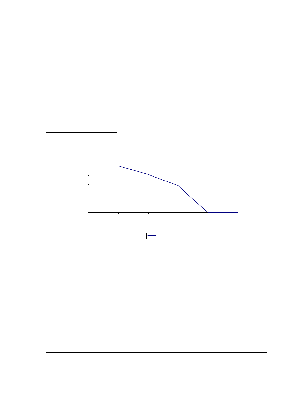
If the temperature of the power frame exceeds 75°C its maximum available current will be
reduced. Note, however, that if the set current limit is less than the maximum available current
limit actual cutback will occur at progressively higher temperatures than 75°C. The thermal
cutback ensures that the maximum heatsink temperature is limited to 90°C (See Graph). When
actual cutback occurs the diagnostic LED will flash 8 times.
Thermal Cutback Characteristic
Current Limit
100
90
80
70
60
50
40
30
Current Limit (%)
20
10
0
70 75 80 85 90 95
Temperature (DegC)
Current Limit
Maximum Temperature Logging
The system maintains a log of the maximum heatsink temperature measured by the controller. The
Maximum Temperature logged is displayed on the Calibrator next to Heatsink Temperature
measurement.
To reset the log select the Maximum Temperature Log reset item on the Calibrator. It will display
'Log'. Press the '+' button and the display will show 'Clr' for 2s before returning back to 'Log'. The
maximum temperature has now been reset to the current heatsink temperature.
MillipaK PUMP Controller Manual Page 35 07/11/05
Page 36

Controller Protection Controller Protection/Timed Cutback
______________________________________________________________________________
Timed Current Cutback
During periods of high current usage the power components of the controller produce
considerable heat. Under normal circumstances the controller will cutback the maximum current
supplied to the load when the heatsink temperature rises above a safe level for the controller
components. However, when the current supplied is close to the maximum rating of the controller
the temperature rise of the components leads the heatsink temperature by up to 40°C. If this
situation was allowed to arise damage may result in the controller. In order to prevent this
situation a timed current cutback feature is incorporated in the MillipaK controller, which works
as described below:
The controller monitors the power through the armature MOSFETs during a 60 second period and
uses the average current seen over this time to determine the new current limit. The new current
limit is then calculated as shown in the table below.
New Current Limit (% of ABR) Current Limit Now
(% of ABR)
Low Power Medium Power High Power
100% 100% 80% 60%
90% 100% 80% 60%
80% 90% 70% 60%
70% 80% 70% 60%
60% 70% 60% 60%
CBR - Is the Controller Block Rating.
The system will limit the current through the motor to the calculated limit during operation.
MillipaK PUMP Controller Manual Page 36 07/11/05
Page 37
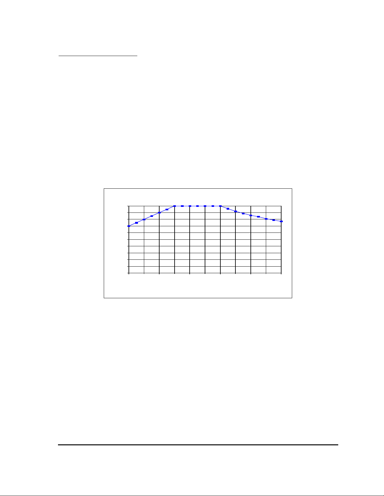
Controller Protection Controller Protection/Safe Operating Area
______________________________________________________________________________
Safe Operating Area (SOA)
The controller’s current may be limited at high and/or low duty cycles depending on its current
and voltage specification. This is to reduce the thermal stress on the power components in order to
increase long term reliability. See Graph 2.
The “Safe Operating Area” is a characteristic of the MOSFETs and Freewheel Diodes which
make up the power-frame. The MOSFET SOA restricts current at high duty cycles on all
configurations, and the Diode SOA tends to restrict the current at lower duty cycles on lower
voltage applications.
For most applications SOA will have little or no effect on the operation of the controller. Its effect
is more significant in protecting the controller against adverse loads such as damaged motors and
static test rigs.
24-48V Controllers
100
90
80
70
60
50
40
30
% of Max. Current
20
10
0
0 20 40 60 80 100
% On
MillipaK PUMP Controller Manual Page 37 07/11/05
Page 38
Controller Protection Controller Protection/Under-voltage protection
______________________________________________________________________________
Under-voltage protection
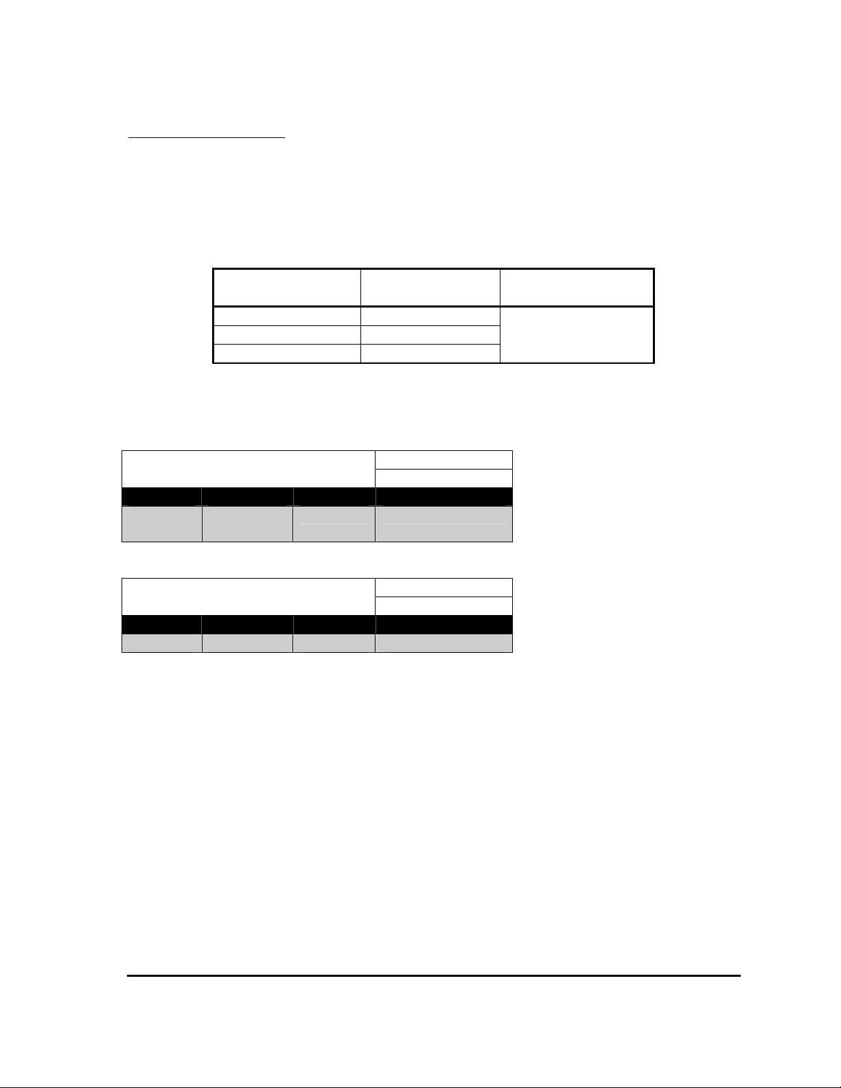
In order to prevent a sudden loss in power, the controller will begin to linearly ramp down the
current limit, once the average battery voltage falls below a pre-set under-voltage start level. The
current will be ramped down to 0 and a 7 flash fault indicated if the averaged battery voltage falls
below the under-voltage cut-out level.
Nominal Battery
Voltage
24 V 14.5V
36 V 14.5V
Under-voltage
Cutout
Under-Voltage Start
(adjustable)
Under Voltage Cut-
out up to System V
48 V 14.5V
The following calibrator menu items are used to set these values.
Immediate Low Voltage Start
Calibrator Menu Reference:
11.03
Minimum Maximum Step Size Typical Value
Low V
Cutout
System
Voltage
0.5V 18.0V
Immediate Low Voltage Cutout
Calibrator Menu Reference:
11.04
Minimum Maximum Step Size Typical Value
14.5V Low V Start 0.5V 16.0V
MillipaK PUMP Controller Manual Page 38 07/11/05
Page 39
Calibr ato r
Refe ren ce
0
1
2
3
4
5
6
7
8
9
10
11
12
SPE ED 1
SPE ED 2
SPE ED 3
SPE ED 4
SPE ED 5
SPE ED 6
SPE ED 7
SPE ED 8
CREE P
RAM P
EX TR A
X2
X3
Desc ript ion
Lif t
Speed 1
Lif t
Speed 2
Lif t
Speed 3
Lif t
Speed 4
Lif t
Speed 5
Lif t
Speed 6
Lif t
Speed 7
Un used
Cre ep
Speed
Ram ps
Po wer
Stee r
Addit ion al
P erson alit ies
Syst em
Setup
1 2 3 ( 16) 4 (17 ) 5 (18 ) 6
T OP
Speed 1 Com p 1
Spee d 2 C omp 2 A ccel 2 Z ero V Accel 2 Ful l V
Speed 3 Com p 3
Spee d 4 Com p 4
Spee d 5 Add / Pr i 5
Spee d 6 Add / Pr i 6
Spee d 7 Add / Pr i 7
Cre ep Sp eed
Lif t Ra mp Up
P S Spe ed PS D elay P S Com p
Cho p Sele ct
P S Ra mp Up
Seat Dela y
Digit al I /O Syst em Volta geAn alogue
Acc el 1 Zer o V Acc el 1 Full V
Ram p D own
Lo w V Cut outLo w V Star tCurr ent Lim it
Inputs
Seat Cuts Lift
xx x
Serv ice L eve l Acc ess
xx x
En ginee ring Lev el Ac cess
All Adjust Lev el A ccess
xx x
7 8 9
Nacc o Calibrator Map for MillipaK Series Pump - 9/11/2001
Navigation
T he ope rato r m ov es t hro ugh t he Calibr ato r M ap by pr essin g th e SELE CT ke y. T h e so lid lin e sho ws th e p ath t he
th rough t he m en u str uctur e when t he SE LEC T k ey is pr essed.
In Servi ce M ode ( no Pa ssword e nt ered) on ly t he ite ms sh own with a t hick sol id bor der ar e disp laye d. W hen th e
ne xt item is h idden (En gine erin g or All a djust a ccess onl y), th e cal ibrat or mov es o n t he nex t dis play able it em .
It ems which are no t c onf igured wil l also be h idden, i e th e by pass item s will not be display ed if th e by pass
co nta cto r is not co nfigur ed.
In En gineer ing M ode (P asswor d ent ere d) t he it em s sho wn wit h a solid borde r ar e disp laye d. W hen th e n ext ite m
is h idden (All a djust acce ss on ly), th e ca librat or mo ves o n t he nex t di splay able item . I tem s whic h ar e n ot
co nfigur ed will a lso be hidde n.
In All A djust Mode (P asswor d en ter ed) al l th e it ems (sol id an d dashe d borde rs) a re di splay ed.
Direction
By default , t he Calibra to r m ove s fro m left to righ t t hr ough the me nu st ruct ure. If t he op erat or pre sses an d ho lds
th e '+' an d '-' key s fo r m ore th an 3 sec onds th e na vigat ion dire ctio n c han ges an d t he C alibrat or will m ove fr om
righ t t o le ft th rough th e m enu struc ture . T he direct ion can be rest ored by h oldin g th e '+' an d '-' key s fo r 3 seco nds
again .
T he direct ion is in dicat ed by th e L ED o n t he Bar Graph . If th e L ED is lit ste adily, th e dire ctio n i s fro m l eft to
righ t, else if th e L ED i s flas hing the direc tio n is fro m r ight to left .
Information Items
T he Tes t m enu only sh ows in for mat ion ite ms t ha t ca nno t be m odifie d. T he ope rat or can mo ve up
an d down th e m enu usi ng t he '+' an d '-' key s. A s befo re, item s wit h a dashe d bor der a re o nly displa yed in Al l
Adjust M ode. I f t he Ope rat or p resse s th e SEL ECT k ey t he Calibr ato r m ov es t o t he n ext m enu.
Item Identification
T he ope rato r c an i dent ify th e cur rent it em by h oldin g down th e '+' and '-' ke ys. For exa mple , h olding down th e
'+' an d '- ' k eys o n t he High V Cut out per sona lity will disp lay 11 .09 (M enu 1 1 ( I.M AX i s men u 0) , It em 9) . T he
op erat or will use th e Use r M anual to iden tify th e p erso nalit y fro m t he ID.
10 1 1
12
13 14
15
13
14
15
16
17
18
19
X4
X5
BAT T
MO TO R (V)
MO TO R (A )
T EMP
T EST
Fault L og
Un used
Syst em
Volt ages
Mo to r
Volt ages
Mo to r
Curr ent s
Hea tsin k
T emp erat ure
T est Men u
Syst em Stat us
Battery Voltage
Motor Voltage
Motor Current
T emp era ture
Acc 1 D ema nd
T OP
Cap . Volt age
Acc 1 Volta ge
Acc 2 D ema nd
Pe rs
Checksum
Acc 2 Vo ltage
Syst em Stat e
Digital 6 SwitchDigital 5 SwitchDigital 4 SwitchDigital 3 SwitchDigita l 2 SwitchDigita l 1 Switch
S/W Versio n
S/W Sub-Rev
Ser N o. Dat e Ser No. I D1 Ser N o. I D2
MillipaK PUMP Controller Manual Page 39 07/11/05
Page 40

Commissioning Checklist
______________________________________________________________________________
Commissioning Checklist
Controller Mounted on suitable flat heatsink with appropriate heatsink compound ?
Power wiring checked, shortest routes taken where possible ?
Light wiring checked, use calibrator to verify controller correct switch operation.
Accelerators set-up and checked 0 – 100% ?
Personalities all set, checked and record filled out ?
MillipaK PUMP Controller Manual Page 40 07/11/05
Page 41
Commissioning Personalities Record
______________________________________________________________________________
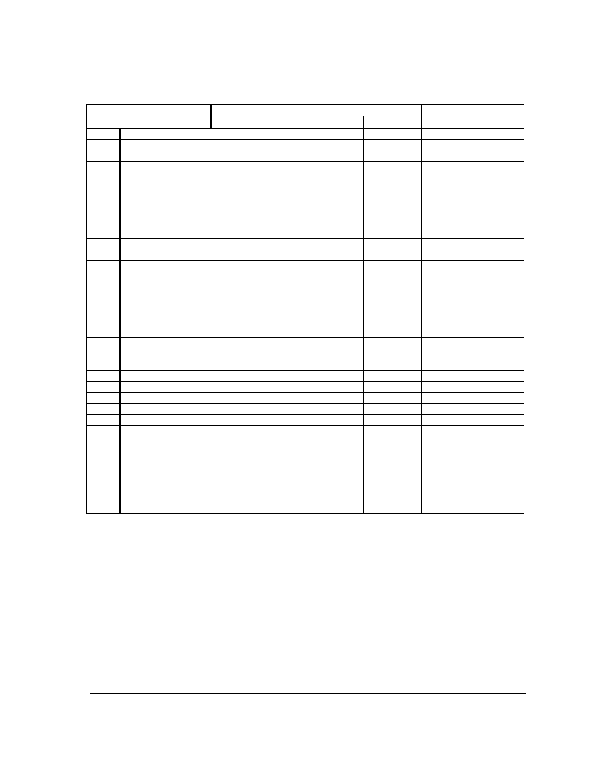
Personality Record
Personality
0.01 Lift Speed 1 0% 100% 1% 100%
0.02 Lift Comp 1 0 200% 1% 0%
0.03 Accel 1 Zero V 0.00V 4.50V 0.02V 0.00V
0.04 Accel 1 Full V 0.00V 4.50V 0.02V 4.50V
1.01 Lift Speed 2 0% 100% 1% 100%
1.02 Lift Comp 2 0 200% 1% 0%
1.03 Accel 2 Zero V 0.00V 4.50V 0.02V 0.00V
1.04 Accel 2 Full V 0.00V 4.50V 0.02V 4.50V
2.01 Lift Speed 3 0% 100% 1% 100%
2.02 Lift Comp 3 0 200% 1% 0%
3.01 Lift Speed 4 0% 100% 1% 100%
3.02 Lift Comp 4 0 200% 1% 0%
4.01 Lift Speed 5 0% 100% 1% 100%
4.02 Speed 5 (P/A) Priority/Additive - Priority
5.01 Lift Speed 6 0% 100% 1% 100%
5.02 Speed 6 (P/A) Priority/Additive - Priority
6.01 Lift Speed 7 0% 100% 1% 100%
6.02 Speed 7 (P/A) Priority/Additive - Priority
7.01 Creep Speed 0% 25% 1% 0%
9.01 Lift Ramp Up Delay 0.1s 5.0s 0.1s 1.5s
9.02 P Steer Ramp Up
Delay
9.03 Ramp Down Delay 0.1s 0.5s 0.1s 0.1s
10.01 P Steer Speed 0% 100% 1% 100%
10.02 P Steer Delay 0s 60s 1s 2s
10.03 P Steer Comp 0 200% 1% 0%
11.01 Current Limit 50A CBR3 10A CBR
11.02 Seat Delay 0.0s 5.0s 0.1s 2.0s
11.03 Low V Start Low V Cutout System
11.04 Low V Cutout 14.5V Low V Start 0.5V 14.5V
12.01 Chop Select Off/On/24V - Off
12.02 Digital I/O 1 2 1 1
12.03 Analogue I/P 0 2 1 1
12.04 System Voltage 24V 48V 2V 24V
New Setting
Minimum Maximum
0.1s 5.0s 0.1s 1.5s
Range
Voltage
Resolution Default
0.5V Low V
Cutout
MillipaK PUMP Controller Manual Page 41 07/11/05
Page 42
Fault Finding
______________________________________________________________________________
Fault Finding
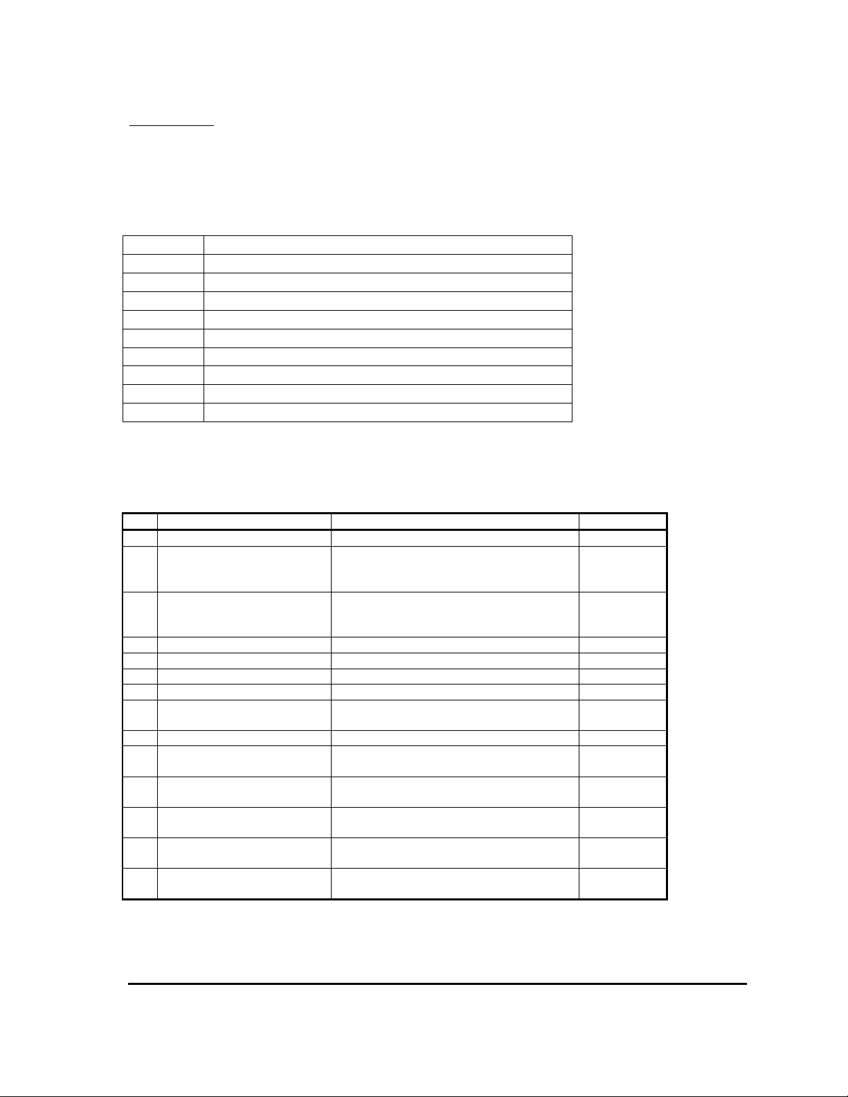
The MillipaK controller includes a number of features designed to help the user track down
operational faults, wiring faults or internal controller faults.
The Diagnostic LED mounted next to the calibrator connectors on the front of the controller
serves as a simple diagnostic tool as explained below:
ON No fault, normal condition
OFF Internal controller fault
1 flash Personality out of range
2 flashes Seat Fault
3 flashes MOSFET Short Circuit
4 flashes Not used
5 flashes Not used
6 flashes Not used
7 flashes Low battery voltage
8 flashes Over temperature or timed cutback
In addition to the LED indication a more detailed description of any faults detected may be found
by using the calibrator. Menu item number 13.01 gives a code which corresponds to the following
detected faults:
ID Fault Description Flash Fault
0 System OK On
1 Thermal Cutback Maximum power available to the motor has
been reduced due to excessive Heatsink
temperature.
2 Timed Current Limit Cutback Maximum power available to the motor has
been reduced by the Timed Current Limit
Cutback function.
3 Low Battery Fault Battery voltage is too low. 7
9 Seat Fault Seat Switch Fault has occurred 2
4 Configuration Range Fault A personality is out of range. 1
5 Configuration CRC Fault The personality CRC is incorrect 1
6 MOSFET On MOSFETs pulsed during power on failsafe
checks (failsafe circuit disabled).
7 MOSFET Short Circuit Short circuit MOSFETs detected. 3
8 MOSFET Short Circuit during
Power Up
10 Drive 1 On Contactor 1 pulsed during power on failsafe
11 Drive 1 Off Contactor 1 did not pulse during power on
12 Drive 2 On Contactor 2 pulsed during power on failsafe
13 Drive 2 Off Contactor 2 did not pulse during power on
Short circuit MOSFETs detected during
power on failsafe checks.
checks (failsafe circuit disabled).
failsafe checks (failsafe circuit enabled).
checks (failsafe circuit disabled)
failsafe checks (failsafe circuit enabled).
8
8
0
3
0
0
0
0
MillipaK PUMP Controller Manual Page 42 07/11/05
Page 43
Fault Finding
______________________________________________________________________________
Fault Clearance
Any fault indication will be cleared by re-initiating the start sequence after the cause of the fault
has been removed. Some faults may only be cleared by re-cycling the key-switch.
Using Status and Test Menus
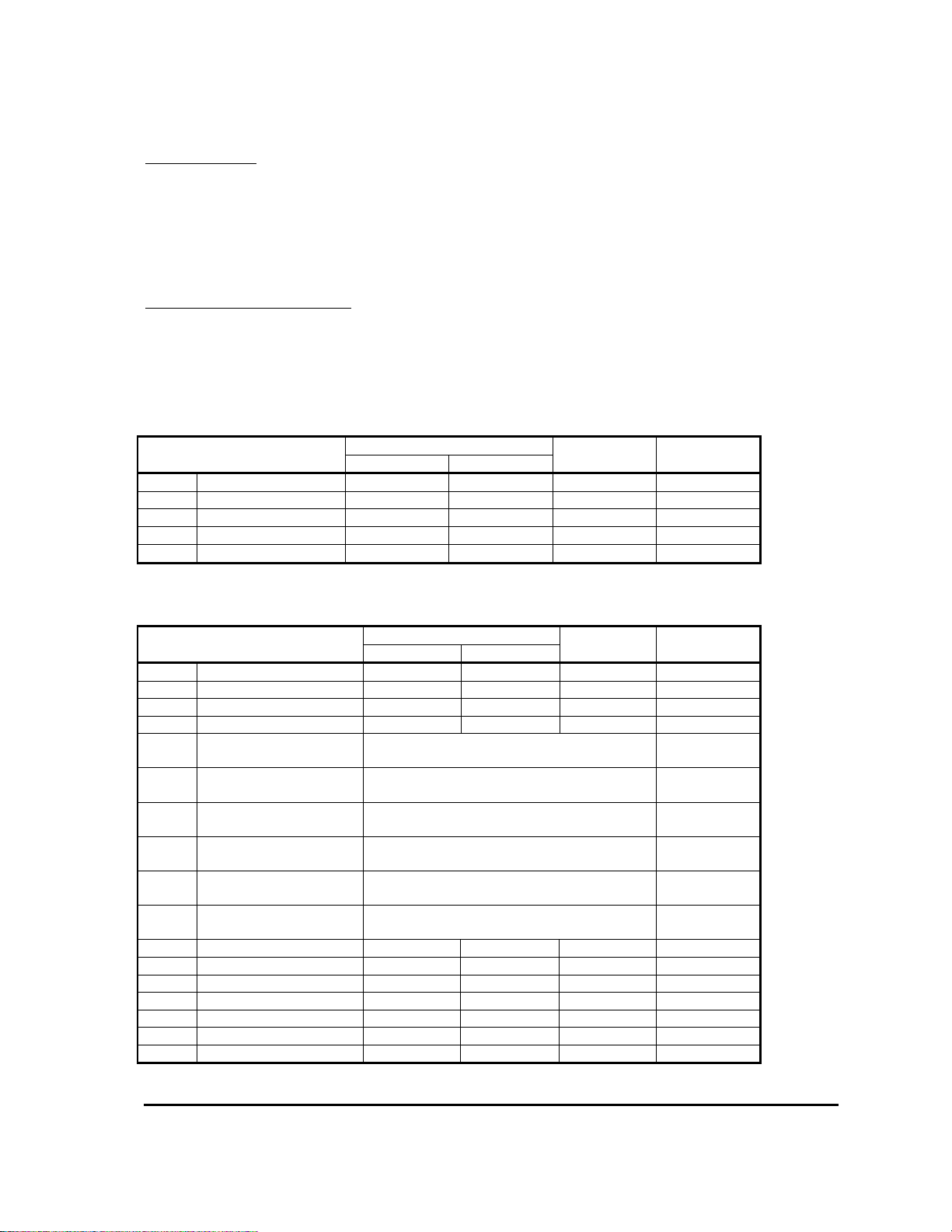
The status and test menus which are available on the calibrator interface can be used to help
pinpoint wiring faults or device failures.
System voltages and currents are available on the following menu items:
Item Range Resolution Display
Minimum Maximum Format
15.01 Battery Voltage 0.0V 63.9V 0.1V
15.02 Capacitor Voltage 0.0V 63.9V 0.1V
16.01 Motor Voltage 0.0V 63.9V 0.1V
17.01 Motor Current 0A 1000A 5A
18.01 Temperature
-30°C 225°C 1°C
000.0
000.0
000.0
x000
x000
Controller analogue and digital input status can be read from the following menu items:
Item Range Resolution Display
Minimum Maximum Format
19.01 Accel 1 Demand 0% 100% 1%
19.02 Accel 1 Voltage 0.00V 5.00V 0.02V
19.03 Accel 2 Demand 0% 100% 1%
19.04 Accel 2 Voltage 0.00V 5.00V 0.02V
19.05 Digital 1 (Pin 2) Open
Closed
19.06 Digital 2 (Pin 3) Open
Closed
19.07 Digital 3 (Pin 4) Open
Closed
19.08 Digital 4 (Pin 5) Open
Closed
19.09 Digital 5 (Pin 6) Open
Closed
19.10 Digital 6 (Pin 7 (switch)
or Pin 11 (analogue))4
19.11 S/W Version 00.00 19.99 0.01
19.12 S/W Sub-Revision 00 99 1
19.13 SN Date Code 0100 1299 1
19.14 SN ID 1 00 99 1
19.15 SN ID 2 00 99 1
19.16 Pers Checksum 0 255 1
19.17 System State 0 13 1
Open
Closed
x000
00.00
x000
00.00
x1.OP
x1.CL
x2.OP
x2.CL
x3.OP
x3.CL
x4.OP
x4.CL
x5.OP
x5.CL
x6.OP
x6.CL
00.00
xx00
0000
xx00
xx00
000
x00
MillipaK PUMP Controller Manual Page 43 07/11/05
Page 44

Fault Finding
______________________________________________________________________________
Also available is information regarding the software revision and manufacturing date (serial
number) – items 19.11 – 19.15. The personality checksum and system state are available on items
19.16 and 19.17 respectively.
MillipaK PUMP Controller Manual Page 44 07/11/05
Page 45
Fault Finding Fault Reporting Form
______________________________________________________________________________
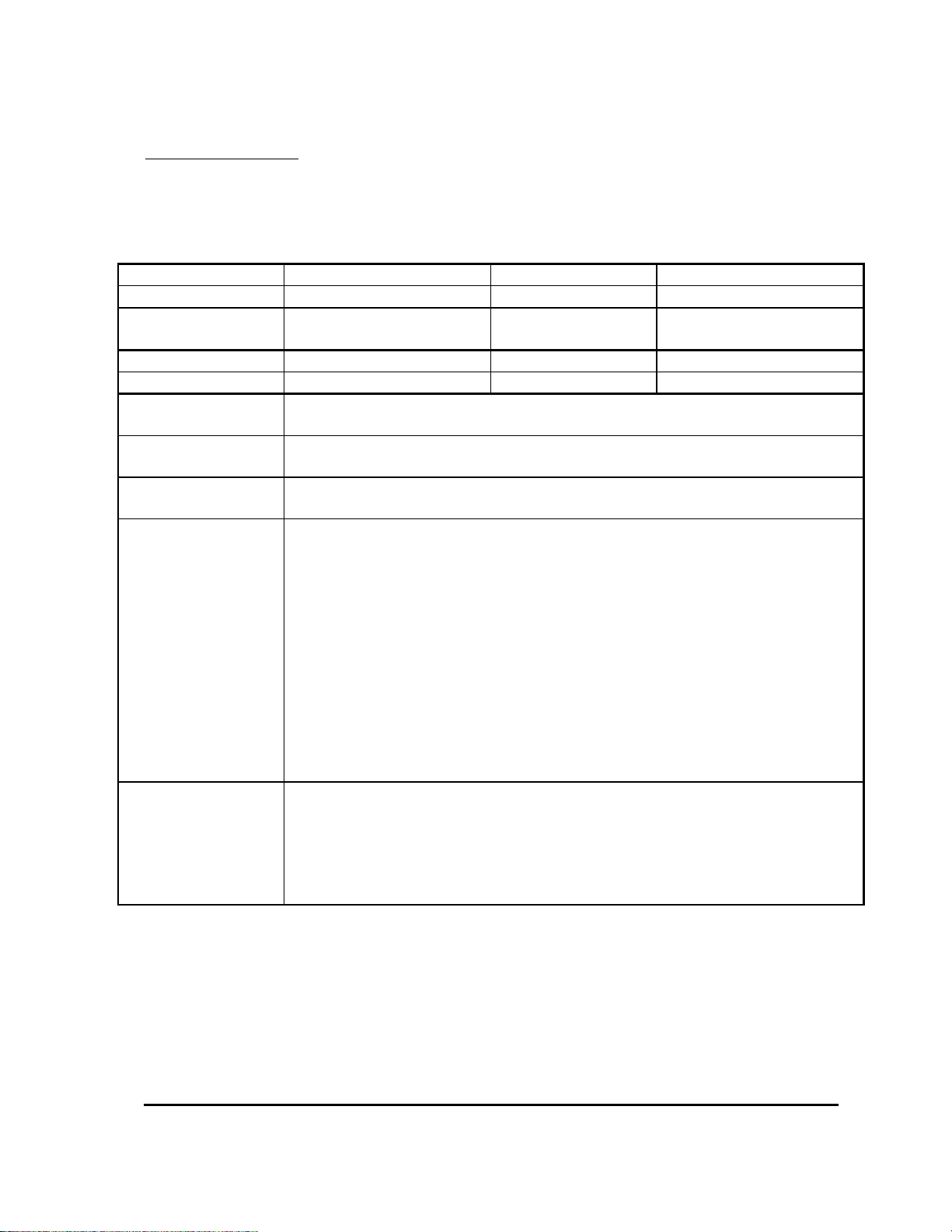
Fault Reporting Form
Sevcon is committed to improving the quality of all its products. Please help us by using this form
to report faults to Sevcon. Please give as much detail as possible. Use extra sheets if required. Fax
this form to +44 191 482 4223.
Your Name Telephone Number
Your Company email address
Vehicle
Vehicle Type
Manufacturer
Controller Type Part number
Serial Number Software Version
Date / Time that fault
first occurred.
Exact Fault Message
(calibrator or display)
When did the fault
message appear?
How did the fault
during drive / when the vehicle stopped / in neutral / after a keyswitch off-on
(delete as applicable)
occur?
Please describe:
The vehicle speed.
The approximate
gradient (up or down
hill)
Pedal and switch
changes by the driver
What happened to
the vehicle when the
fault occurred
What is the status of
the vehicle now?
Is there a fault
message at keyswitch on?
Can it be driven?
MillipaK PUMP Controller Manual Page 45 07/11/05
Page 46

Fault Finding Fault Reporting Form
______________________________________________________________________________
Software Version and Serial Number indication
For identification purposes and to assist in queries, the Software version, and the controller serial
number are indicated in the calibrator Test Menu.
The Software version is shown across two items in the Test menu. The first item is the version
and the second is the sub-revision. Both these items need to be used to get the complete software
version number. The format is:
Test Item:
Version Number:
S/W Version S/W Sub-Rev
MM.mm ss
When giving the Software Version, the entire number should be quoted (i.e. MM.mm.ss).
The Serial Number is shown across three items in the Test menu. The first item is the date code
and the next two are the identifier. All these items need to be used to get the complete serial
number. The format is:
Test Item:
Serial Number:
Ser No. Date Ser No. ID1 Ser No. ID2
MMYY AA BB
MMYY gives the month and year when the controller was manufactured. (e.g. 0701 indicates
July, 2001). AABB are combined to give a 4 digit identifier which is simply a number from 0001
to 9999. When giving the Serial Number, the entire number should be quoted (i.e.
MMYYAABB).
The MillipaK range of controllers use the latest FLASH technology to allow In System
Reprogramming. This is achieved without having to remove the controller from its installation –
all that is needed is connection to the 6-way calibrator socket.
MillipaK PUMP Controller Manual Page 46 07/11/05
Page 47
Specifications
______________________________________________________________________________
Specifications
The following specifications apply to all MillipaK Pump controllers.
Power Configurations
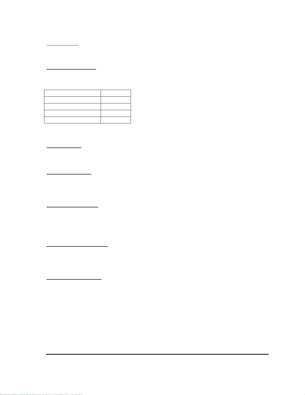
At present the MillipaK PUMP controller is available in the following power configurations:
Housing Armature
(CORE) Small 180A
(CORE) Small 300A
(HP) Large 600A
(HP) Large 450A
All the MillipaK PUMP range of controllers operate from 24-48v batteries.
EMC standards
All MillipaK variants are tested to and conform to EN12895.
Socket B protection
All user connections on socket B are protected against indefinite short circuit to battery minus and
battery positive.
Contactor drive ratings
All contactor drives are rated at 3A peak (10s) and 1.5A continuous. All the drives have reverse
battery connection protection, inbuilt freewheel diode and are internally protected against short
circuit.
Analogue Input Impedance
The two analogue inputs are internally pulled up to +12v via a 12k resistor. This is primarily
designed for use with 5k potentiometers, but may also be used with suitable voltage sources.
Digital Input Impedance
The digital inputs are internally pulled up and are active LOW. They therefore must be connected
to battery minus to operate a function. Maximum resistance to battery minus to operate is
500ohms.
MillipaK PUMP Controller Manual Page 47 07/11/05
Page 48

EMC Guidelines
______________________________________________________________________________
EMC Guidelines
The following guidelines are intended to help vehicle manufacturers to meet the requirements of
the EC directive 89/336/EEC for Electromagnetic Compatibility.
Any high speed switch is capable of generating harmonics at frequencies that are many multiples
of its basic operating frequency. It is the objective of a good installation to contain or absorb the
resultant emissions.
All wiring is capable of acting as a receiving or transmitting antenna. Wiring should be arranged
to take maximum advantage of the structural metal work inherent in most vehicles. Vehicle
metalwork should be electrically linked with conductive braids.
Power Cables
All cables should be routed within the vehicle framework and kept as low in the structure as is
practical - a cable run within a main chassis member is better screened from the environment than
one routed through or adjacent to an overhead guard.
Power cables should be kept short to minimise emitting and receiving surfaces
Shielding by the structure may not always be sufficient - cables run through metal shrouds may be
required to contain emissions.
Parallel runs of cables in common circuits can serve to cancel emissions - the battery positive and
negative cables following similar paths is an example.
Tie all cables into a fixed layout and do not deviate from the approved layout in production
vehicles. A re-routed battery cable could negate any approvals obtained.
Signal Cables
All wiring harnesses should be kept short.
Wiring should be routed close to vehicle metalwork.
All signal wires should be kept clear of power cables or made from screened cable
Control wiring should be kept clear of power cables when it carries analogue information - for
example, accelerator wiring.
Tie all wiring securely and ensure wiring always follows the same layout.
Controller
Thermal and EMC (emissive) requirements tend to be in opposition.
Additional insulation between the controller assembly and the vehicle frame work reduce
capacitive coupling and hence emissions but tend to reduce thermal ratings. A working balance
needs to be established by experiment.
The complete installation should be documented, in detail, and faithfully reproduced on all
production vehicles. When making changes, consider their effect on compliance ahead of any
consideration of cost reduction or other “improvement”.
MillipaK PUMP Controller Manual Page 48 07/11/05
Page 49

Ordering Information Part Numbers
______________________________________________________________________________
Ordering Information
The controllers and contactor panels are allocated 633 numbers as shown. The lettering section
gives the full listing of item types.
item description voltage current logic Customer Code
A= 2= 24 1= 100-199 1= SEM plug XX
B= 3= 36 2=.200-299 2= SEM plug s/start
C= Controller only 4= 48 3= 300-399 3= SEM regen
D= Traction panel 7 = 72 4= 400-499 4= SEM regen s/start
E= Traction + Pump Panel 8= 80 5= 500-599 5= Series Pump
F= Twin Traction Panel 9= 96 6= 600-699 6= BPM
G= Twin Traction + Pump Panel 7= 700-799 7= BPM s/start
H= 8= 800-899 8= 4QPM
J= 9= 900 + 9= 4QPM s/start
K=
L=
M=
N=
P=
R=
S=
T= HP Controller only
W= HP Traction panel
X= HP Traction + Pump Panel
Y= HP Twin Traction Panel
Z= HP Twin Traction + Pump Panel
HP = High Power
For panels then the voltage, current and logic numbers should be used to describe the traction
controller.
Examples:
300A SEM plugging controller with soft start 633C43101
600A SEM plugging controller 633T46101
MillipaK PUMP Controller Manual Page 49 07/11/05
 Loading...