

Page 1

WARRANTY
SEVA BT-2000 GATE & SYSTEM WARRANTS against defects on material and
workmanship in normal use. Bangsan Technologies, Inc. will, at its option, replace or
repair any defective electronic part within one year but other parts within two years
from the date of purchase/delivery.
If this product is serviced by unauthorized personnel, this warranty will become void
and Bangsan Technologies, Inc. will not be responsible for its consequences. Since this
product function is affected, to a certain degree, by external factors that are beyond
manufacturer’s control, Bangsan Technologies, Inc. will not be responsible for
direct/indirect damages to persons or equipment caused by negligence or misuse.
INSTALLATION INSTRUCTION.
GENERAL NOTES
z Detector installation area should be flat.
z Two pedestals must be aligned as per provided information
z Side panels must be perpendicular to the ground after installation
z Detector side panels must be 500mm away from the door if door frame is made
out of metal.
z No holes are allowed to be drilled to any part of the detector without
permission of authorized service personnel.
z It is recommended to have a power outlet at the ceiling for the easier
connection to the detector.
Prior to installation, all warnings and cautions should be followed and observed very
carefully. Bangsan Technologies will not be responsible for the damages done to the
SEVA BT-2000 system which may be caused by not following the instructions in this
manual.
Mechanical Interference
Moving Door: Locate the detector minimum of 500 mm away from the door. Make
sure that door swings outward. If door is double door type, detector should be installed
on one side of double doors. The other door is recommended to be locked. If the door is
metal type, it is recommended to insulate its metal looping by cutting one edge of the
door metal frame. Check the swinging door effect to the detector by swinging after
installation of the detector. If detector is still affected by swinging door, install door
closer system (P/N: SEVA-05) which is provided with detector as per its installation
instruction.
Nearby Moving Object: If the detector is installed too close to the road, large
moving vehicle may affect its function. Therefore, it is recommended to install the
detector away from the road as far as it can.
- 1 -
Bangsan Technologies Inc.Sentry SystemSEVA
Page 2

Electrical Interference
There are many sources which may cause electrical interference problems to the
detector. They are electric motors, neon signs, CRT type TV & computer monitors,
power line, telephone line, cellular phones. They should be located away from the
detector. If serious interference is detected continuously, consult with your dealer.
Electrical power cords should be at a distance of minimum 150 mm from the side
panels.
INSTALLATION OF DETECTORS IN SERIES
The minimum distance between two detectors should be maintained at a distance of
500mm.
MAINTENANCE MANUAL
Before working on electricity or any electronic parts, make sure that electrical power is
disconnected.
How to remove Electronic Board
Remove the mounting screws from the bridge cover (P/N : BR-003) located at the
center of Bridge. Remove four screws at each corner of the board. Disconnect all
connectors carefully from the board. Pull out board.
How to remove Power Supply Board
Remove four mounting screws from the bridge cover (P/N : BR-003) located at Bridge.
Power supply board will be shown from the hole. Remove 4 screws from the mounted
hinges, Disconnect 8 wires from the board. Board is free to remove.
How to get its replacement parts and its reinstallation
Send the disabled boards to the authorized service center for its replacement parts.
After receiving replacement part, you should place new part to the detector. Installation
procedure is exactly opposite of removal procedure.
- 2 -
Bangsan Technologies Inc.Sentry SystemSEVA
Page 3

Table of Contents
1. Seva Sentry System....................................................4
2. Detector Dimension....................................................5
3. Controller Connectors.................................................6
4. Mechanical Assemble..................................................7
5. Electronic Display Operation.....................................13
6. Installation of Door Brake System.............................15
7. Operation of Controller..............................................17
8. Specifications.............................................................20
9. Test.............................................................................21
9-1 Program Setting...............................................21
9-2 Test Condition.................................................21
9-3 Test Pieces......................................................22
9-4 Test Result......................................................23
Bangsan Technologies Inc.Sentry SystemSEVA
- 3 -
Page 4
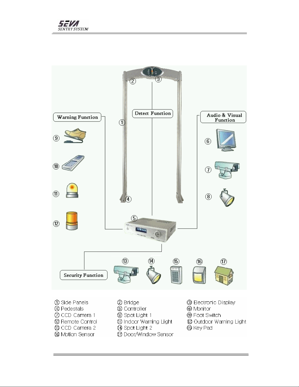
1. SEVA SENTRY SYSTEM
Bangsan Technologies Inc.Sentry SystemSEVA
- 4 -
Page 5
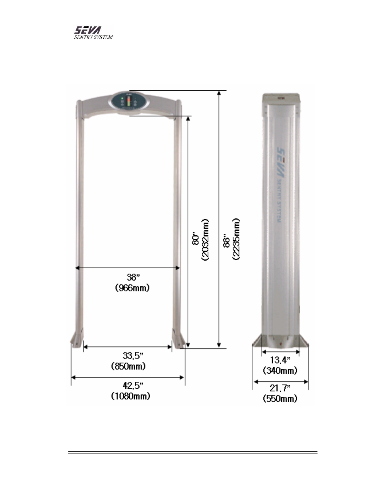
2. DETECTOR DIMENSION
Bangsan Technologies Inc.Sentry SystemSEVA
- 5 -
Page 6
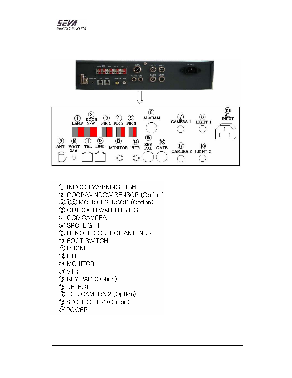
3. CONTROLLER CONNECTORS
Bangsan Technologies Inc.Sentry SystemSEVA
- 6 -
Page 7
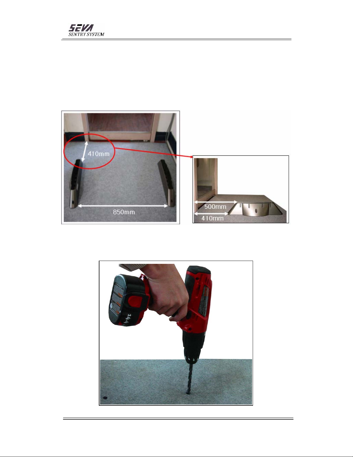
4. Mechanical Assembly
4-1. Locate two pedestals 410mm away from the door (distance from door to side
panel is 500mm) and mark the anchor hole locations (6 holes).
4-2. Remove the pedestals and drill anchor holes (3/8” drill x 1-1/2” deep) and fix 6
anchor bolts through holes.
- 7 -
Bangsan Technologies Inc.Sentry SystemSEVA
Page 8
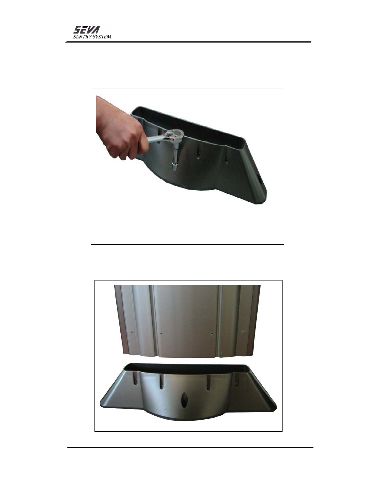
4-3. Place two pedestals on both sides over anchor bolts (3 places – each). Tighten
the nuts (6Φ mm – 3 places each) after inserting washers.
4-4. Place side panels on the left and right pedestals.
- 8 -
Bangsan Technologies Inc.Sentry SystemSEVA
Page 9
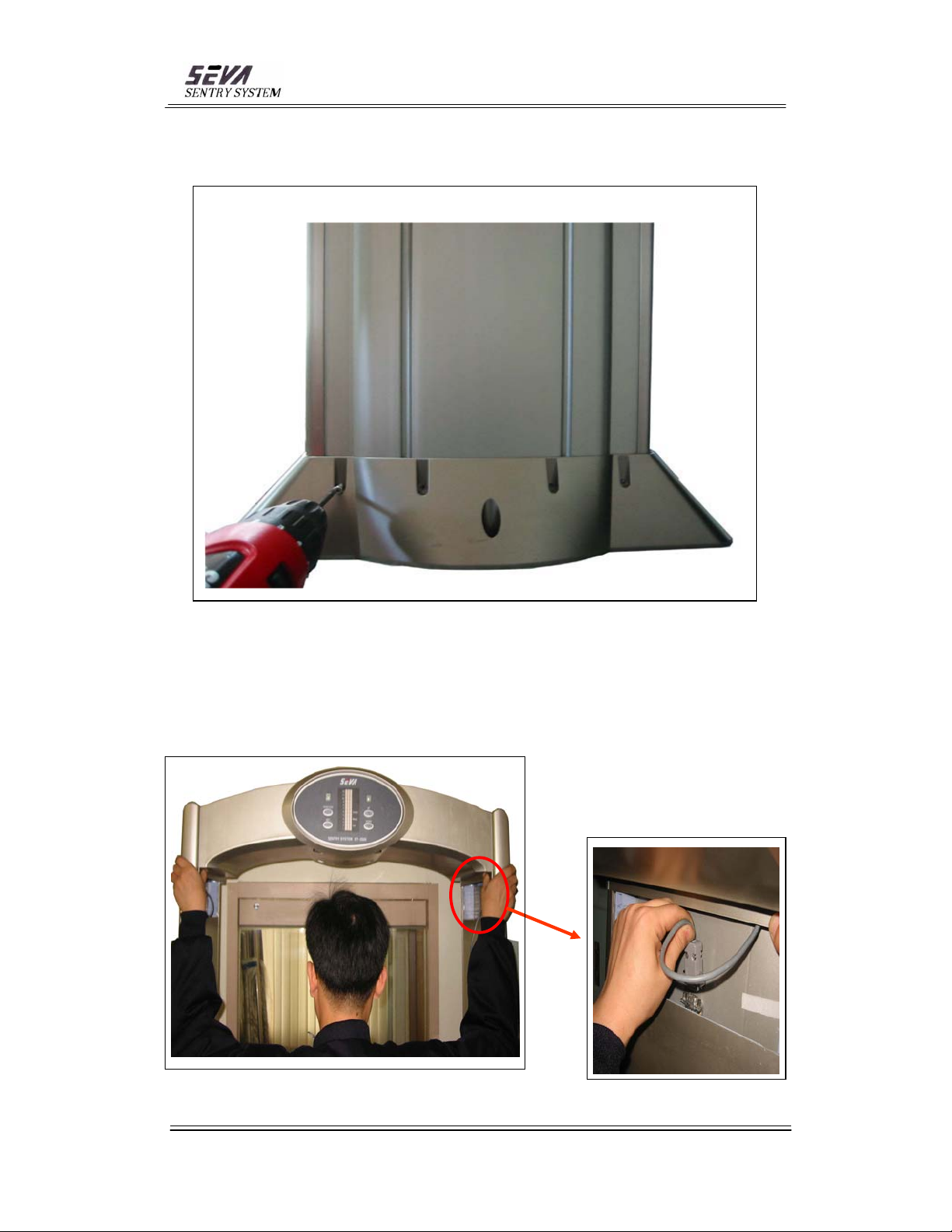
4-5. Tighten 4 screws (4x70mm) on each pedestal to the side panel
4-6. Before placing the bridge, make sure that electronic display faces away from the
door. Connect 9 pin data connectors from the bridge to the side panels (1 place per
side).
Bangsan Technologies Inc.Sentry SystemSEVA
- 9 -
Page 10
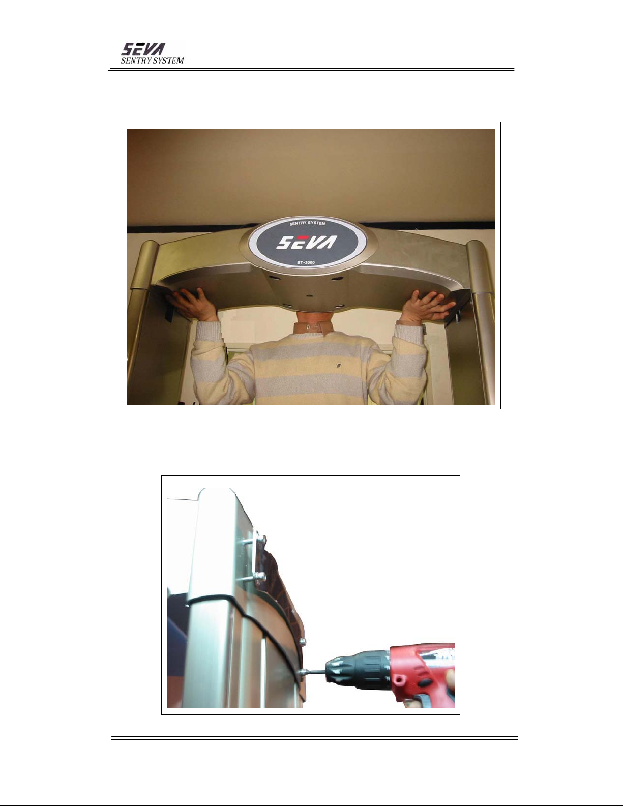
4-7. After connectors are connected to the side panels, snug in Bridge to Side Panels.
4-8. Place 4x60mm bolts and 5mm washers (4 places-each side) to the bridge to
connect bridge and side panels. Make sure stainless steel stiffener is placed.
- 10 -
Bangsan Technologies Inc.Sentry SystemSEVA
Page 11
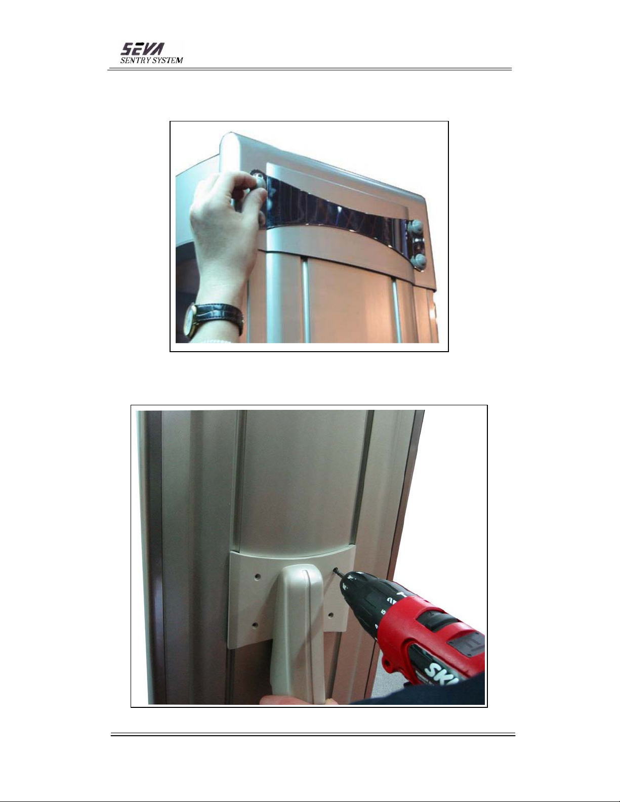
4-9. Place plastic caps over the bolt heads ( 4 places – each side).
4-10. Place panel supports to the side panel and screw the bolts (4 x 20mm) with
washers (5mm).
- 11 -
Bangsan Technologies Inc.Sentry SystemSEVA
Page 12
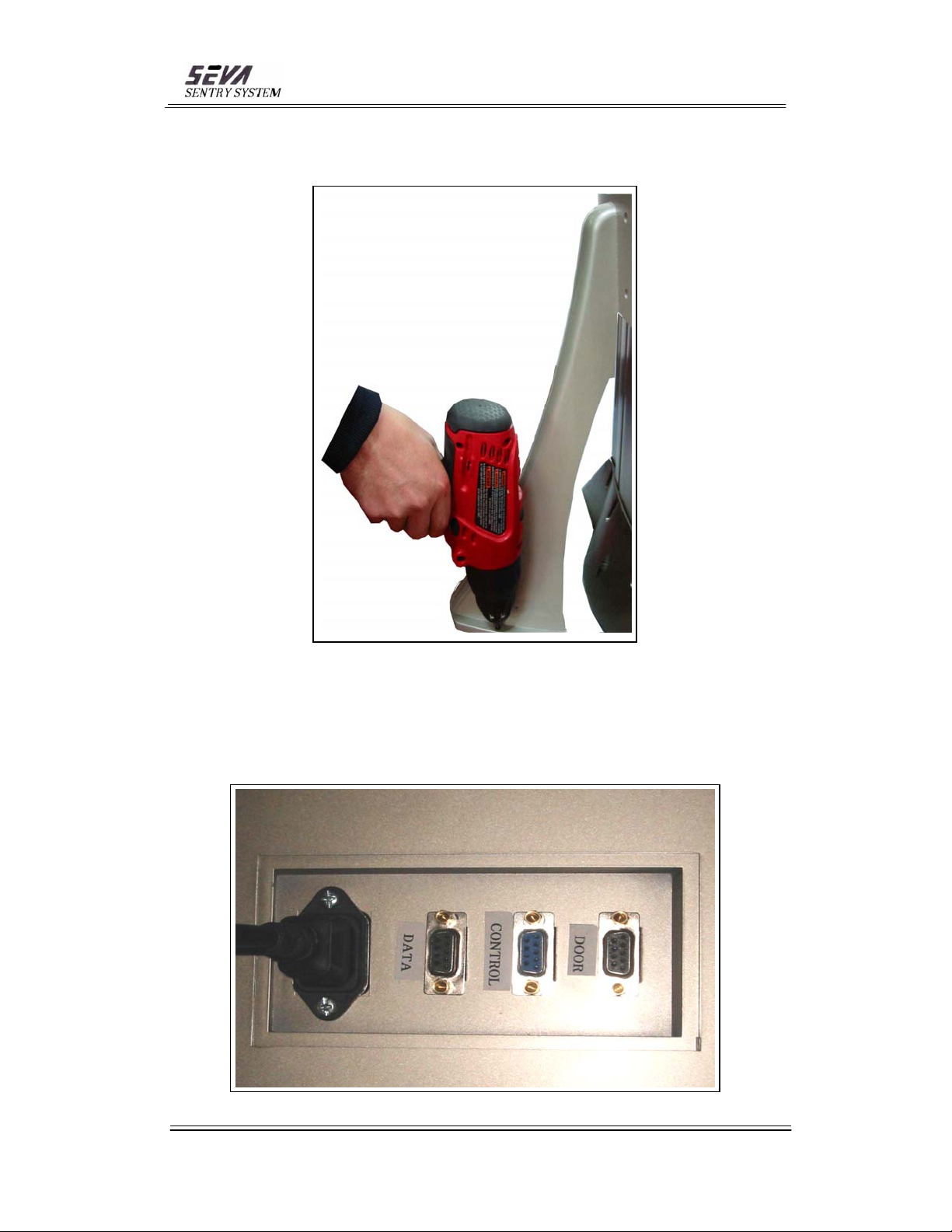
4-11. Place anchor bolts (6 x 53mm) to the panel supports floor.
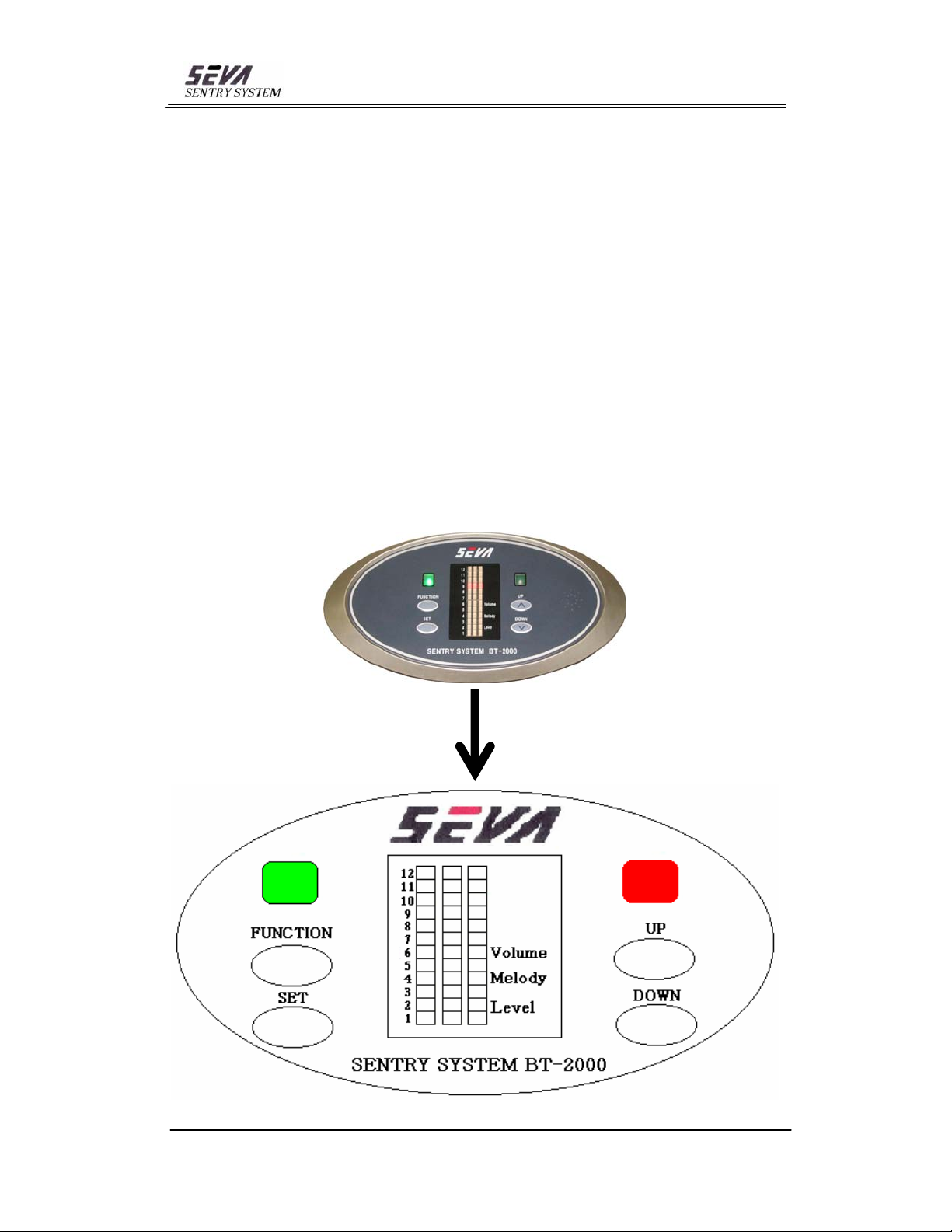
4-12. Plug in power cord to the power connector located on the top of the bridge
4-12-1 Data : This port will not be used
4-12-2 Control : Controller Gate connector
4-12-3 Door : Door Brake connector
.
- 12 -
Bangsan Technologies Inc.Sentry SystemSEVA
Page 13
Caution :
* Installation floor must be flat.
* Gate should be installed 500mm away from the door (410mm away from the tip of
the pedestal).
* Two pedestals must be in parallel.
* The distance between two panels is 850mm.
* Electronic Display side on the bridge must face away from the door.
* If the floor reflects the beam from the top sensors, carpeting is necessary under the
bridge area.
5. ELECTRONIC DISPLAY OPERATION
After connecting to power source, 12 LED lights on Electronic Display will light in
sequence from the bottom to the top and green light on the left, red light on the right
will be lit. Finally, green light on the left will lit and the detector will be ready for its
operation.
- 13 -
Bangsan Technologies Inc.Sentry SystemSEVA
Page 14
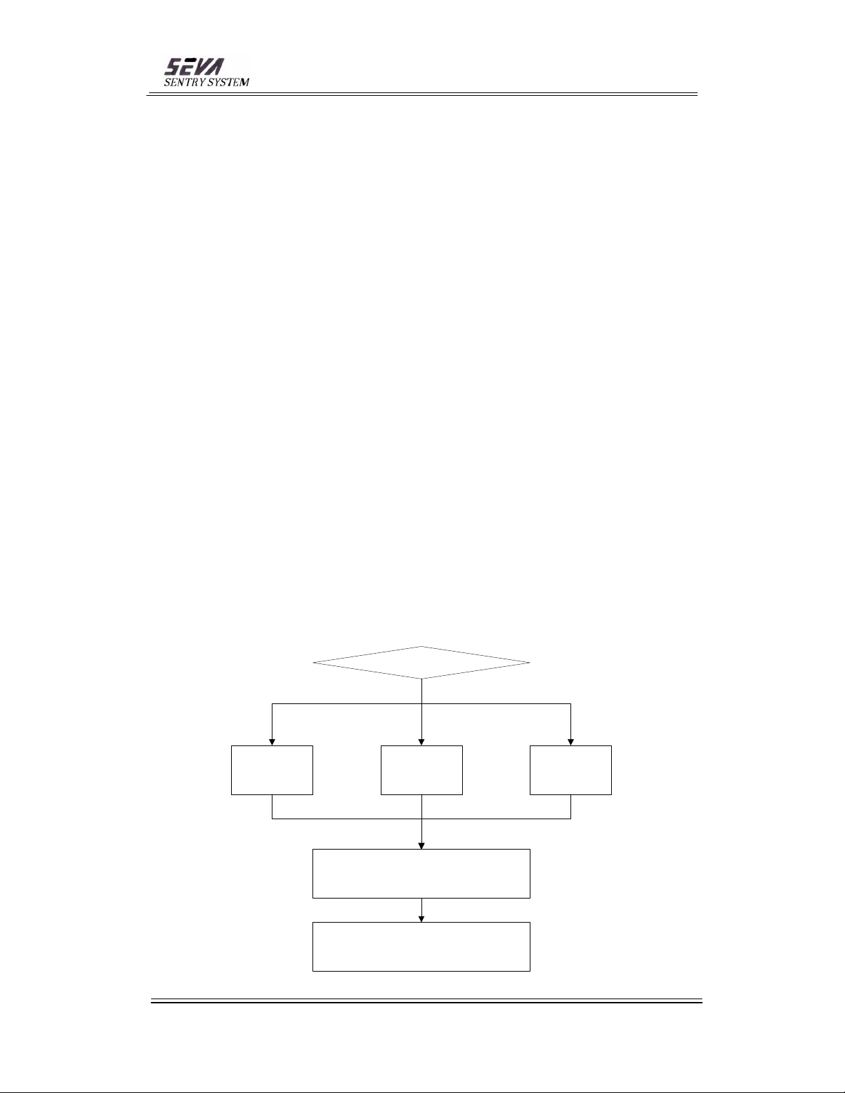
5-1. Function Key
This key controls the selection of programs of Volume, Melody, Level which will
be lit in turn by pressing this key.
5-2. Set Key
This key stores the program to the system for use.
5-3. Up Key
The value of the set program will increase.
5-4. Down Key
The value of the set program will decrease.
5-5. Example
5-5-1. When controlling the volume, press Function Key until the yellow light
reaches to Volume on Electronic Display. Then, press UP/Down Key to reach
to the desired volume.
5-5-2. When choosing the different melody, press Function Key until yellow light
reaches to Melody. Press Up/Down Key to select the desired melody. Press Set
Key.
5-5-3. When selecting different sensitivity level, press Function Key until the
yellow light reaches to Level. Press Up/Down Key to select desired level. Press
Set Key.
5-6. Electronic Display Diagram
Function Key
# 1 # 2 # 3
Volume Melody Level
UP/ DOWN Key
SET Key
Bangsan Technologies Inc.Sentry SystemSEVA
- 14 -
Page 15
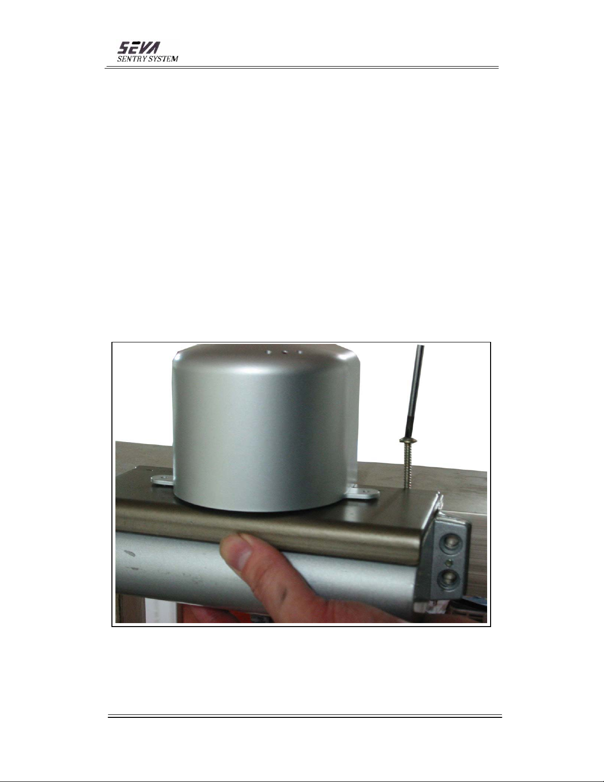
6. DOOR BRAKE SYSTEM (SEVA-05)
This is a patented system to control the door movement to minimize mechanical
interference effect to the detector. Door Brake System will hold the door open until a
person passes through the detector.
The followings are the differences from the existing door closer
6-1. This system is equipped with electronic brake.
6-2. A sensor is installed on the door frame to control the system function.
6-3. Installation
6-3-1. Its installation method is exactly same as the existing door closer except
it requires two extra screws (4x30mm – each side) to place electronic
brake on its top..
Bangsan Technologies Inc.Sentry SystemSEVA
- 15 -
Page 16
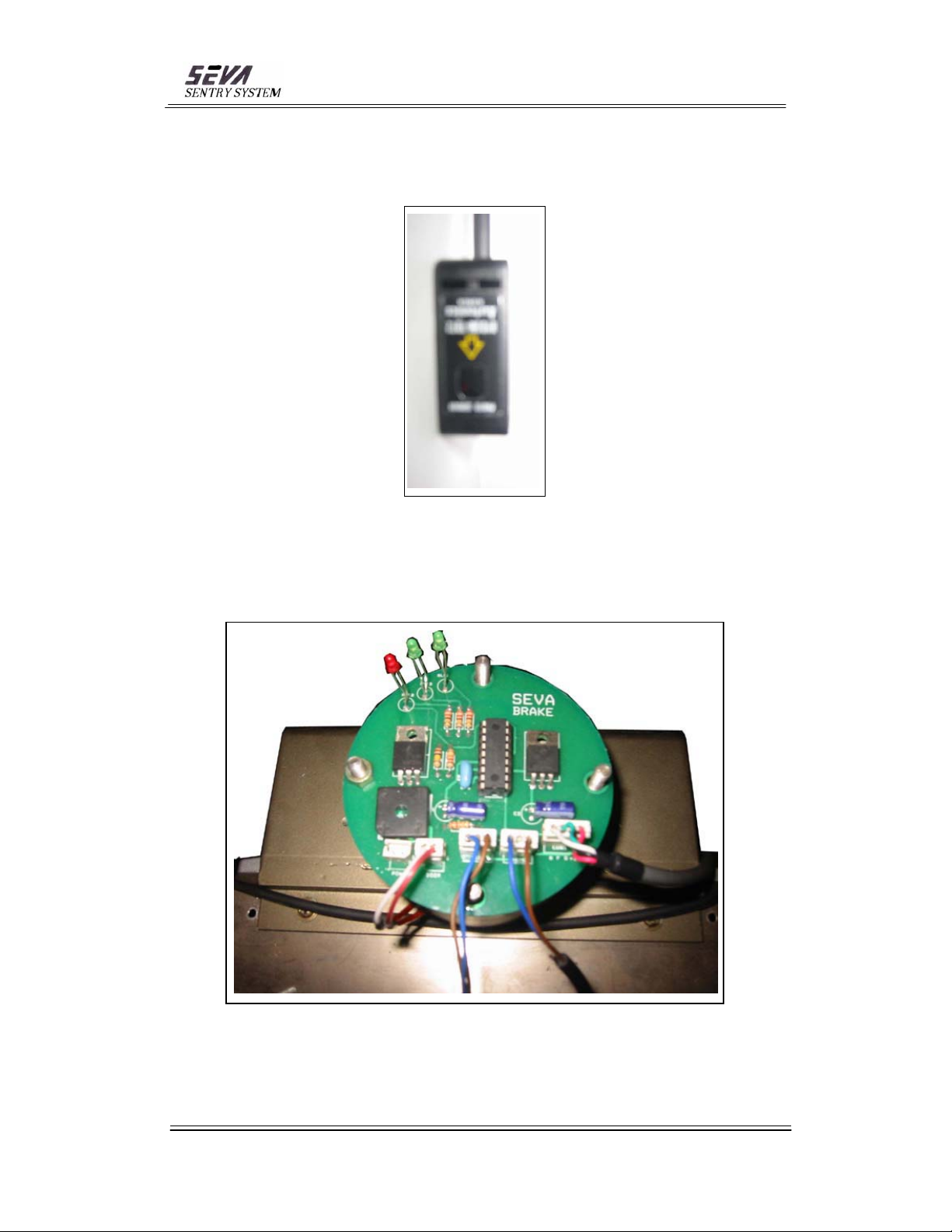
6-3-2. Door brake sensors should be installed on the door frame at the 750mm
above from the floor. (Refer to attached manual)
6-3-3. Remove the door brake cover and find markings of "dsen", "conl",
"power". Connect two sensor lines to "dsen" and cable from detector
(see 4-12-3) to "conl", and DC adaptor cable connector to "power".
Bangsan Technologies Inc.Sentry SystemSEVA
- 16 -
Page 17
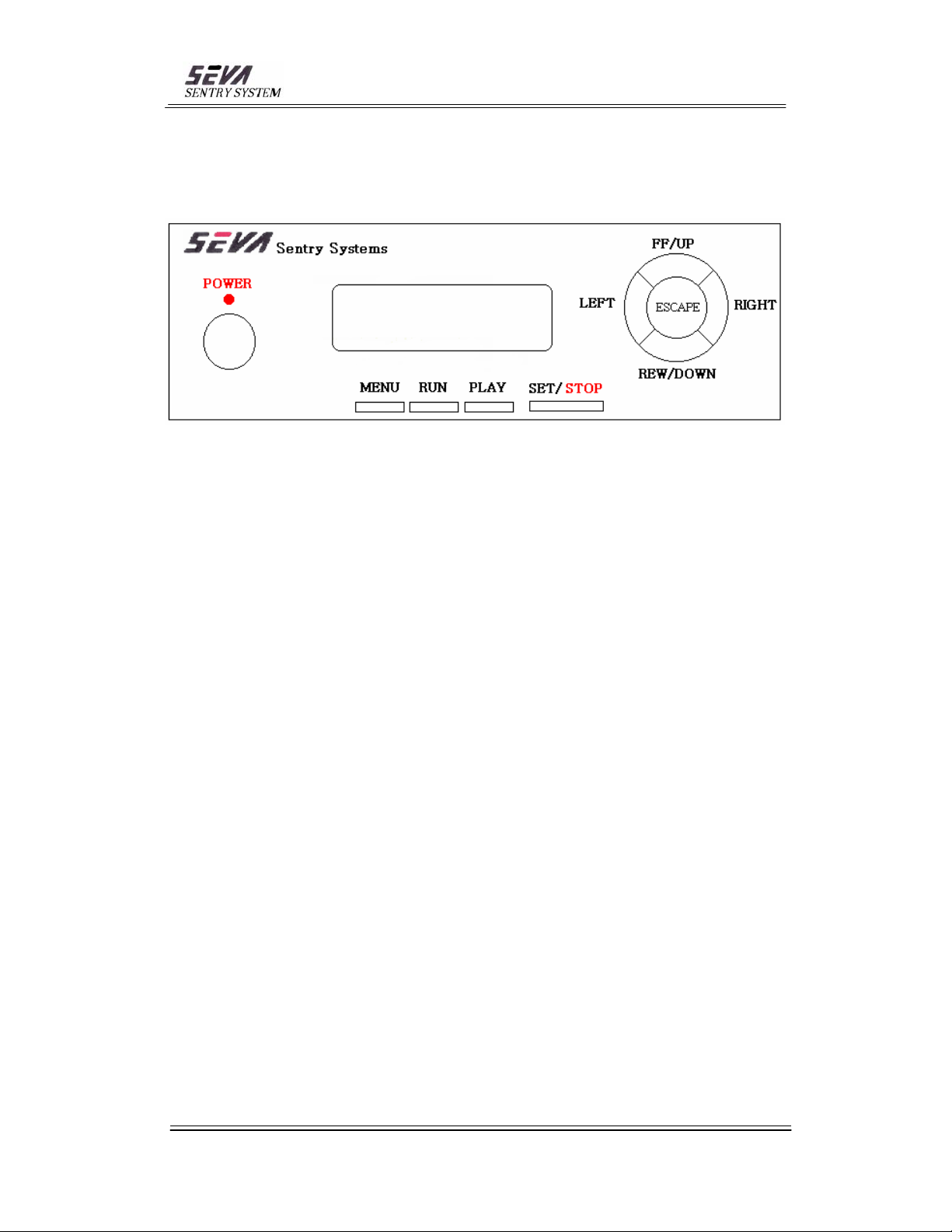
7. OPERATION OF CONTROLLER (SEVA-04)
7-1. Turn on the Controller.
7-2. Press the MENU button once
7-3. Select Menu by using FF/UP or REW/DOWN
DATE : Current date
OSD: Selecting date, time, photo numbers on monitor when weapon is detected.
ALARM ID : Designate number to Motion Sensors
LIGHT : GUN - Light will be lit when the weapon is detected
ALWAYS - Light will be lit when a person passes the gate
MELODY : Selection of melody alarm when weapon is detected.
OFF(LAMP ON) : No melody but Indoor Warning light will be on.
PLAY BY SENSOR : Image showing time on the monitor when weapon is
detected.
PLAY FOR 00S - flash
PLAY FOR 10S - 1 second
PLAY FOR 30S - 3 second
PLAY FOREVER – until new image
SEND MESSAGE : Storing phone numbers for emergency calls
TELEPHONE : Five phone numbers can be stored for emergencies. Phone
numbers will be dialed automatically when pressing the remote
control button, foot switch or door/window sensor & motion
sensors are activated.
PASS WORD : Storing phone numbers for emergency calls
DATE FORMAT : YYYY/MM/DD --> Year, Month, Date sequence
MM/DD/YYYY --> Month, Date, Year sequence
DD/MM/YYYY --> Date, Month, Year sequence
TIME : Hour, Minute, Second sequence
- 17 -
Bangsan Technologies Inc.Sentry SystemSEVA
Page 18

7-4. After new input or correction is made, press SET/STOP button for storage.
7-5. RUN : Detection function is activated
7-6. PLAY : Search function of stored images.
Press PLAY button. Press FF/UP REW/DOWN or LEFT/RIGHT until
Desired image is obtained.
To return to Detection Function. Press RUN.
- 18 -
Bangsan Technologies Inc.Sentry SystemSEVA
Page 19
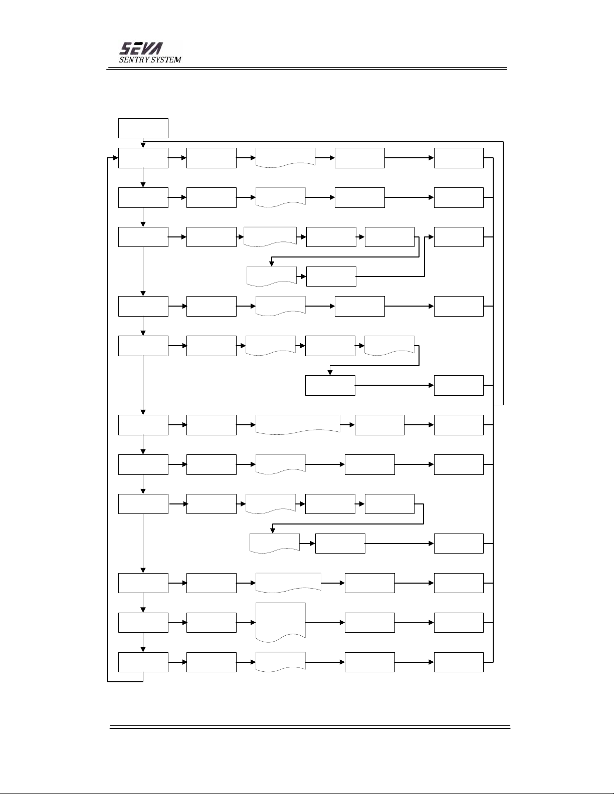
7-7. Controller Operation Diagram
MENU
DATE
OSD
ALARM ID
LIGHT
MELODY
PLAY BY
SENSOR
SET/ STOP
SET/ STOP
SET/ STOP
SET/ STOP
SET/ STOP
SET/ STOP
DATE MM / DD/ YYYY
00/ 00/2000
ON or OFF
ALARM ID 1 ~ 4
??? ~ 999
GUN or ALWAYS
1 ~ 5 and
OFF(LAMP ON)
PLAY BY SENSOR PLAY FOR
(00S, 10S, 30S, EVER)
UP/ DOWN/LEFT/
RIGH T
UP/ DOWN
UP/ DOWN SET/ STOP
UP/ DOWN/LEFT/
RIGH T
UP/ DOWN
UP/ DOWN
VOLU ME 1 ~ 8
UP/ DOWN
UP/ DOWN
SET/ STOP
SET/ STOP
SET/ STOP
SET/ STOP
SET/ STOP
SET/ STOP
SEND
MESSAGE
TELEPHONE
PASSWORD
DATA
FORMAT
TIME
SET/ STOP
SET/ STOP
SET/ STOP
SET/ STOP
SET/ STOP
SEND MESSA GE
????? ~ 99999
TELEPHONE
No. 1 ~ No.5
????????????? ~
9999999999999
PASSWORD
???????? ~ 9999999 9
DATE FORMAT
(MM/ DD/YYYY
YYYY/ MM/ DD
DD/MM/ YYYY)
TIME HH:MM:SS
PM 00:00:00
UP/ DOWN/LEFT/
RIGH T
UP/ DOWN SET/ STOP
UP/ DOWN/LEFT/
RIGHT
UP/ DOWN/LEFT/
RIGH T
UP/ DOWN
UP/ DOWN/LEFT/
RIGH T
- 19 -
SET/ STOP
SET/ STOP
SET/ STOP
SET/ STOP
SET/ STOP
Bangsan Technologies Inc.Sentry SystemSEVA
Page 20
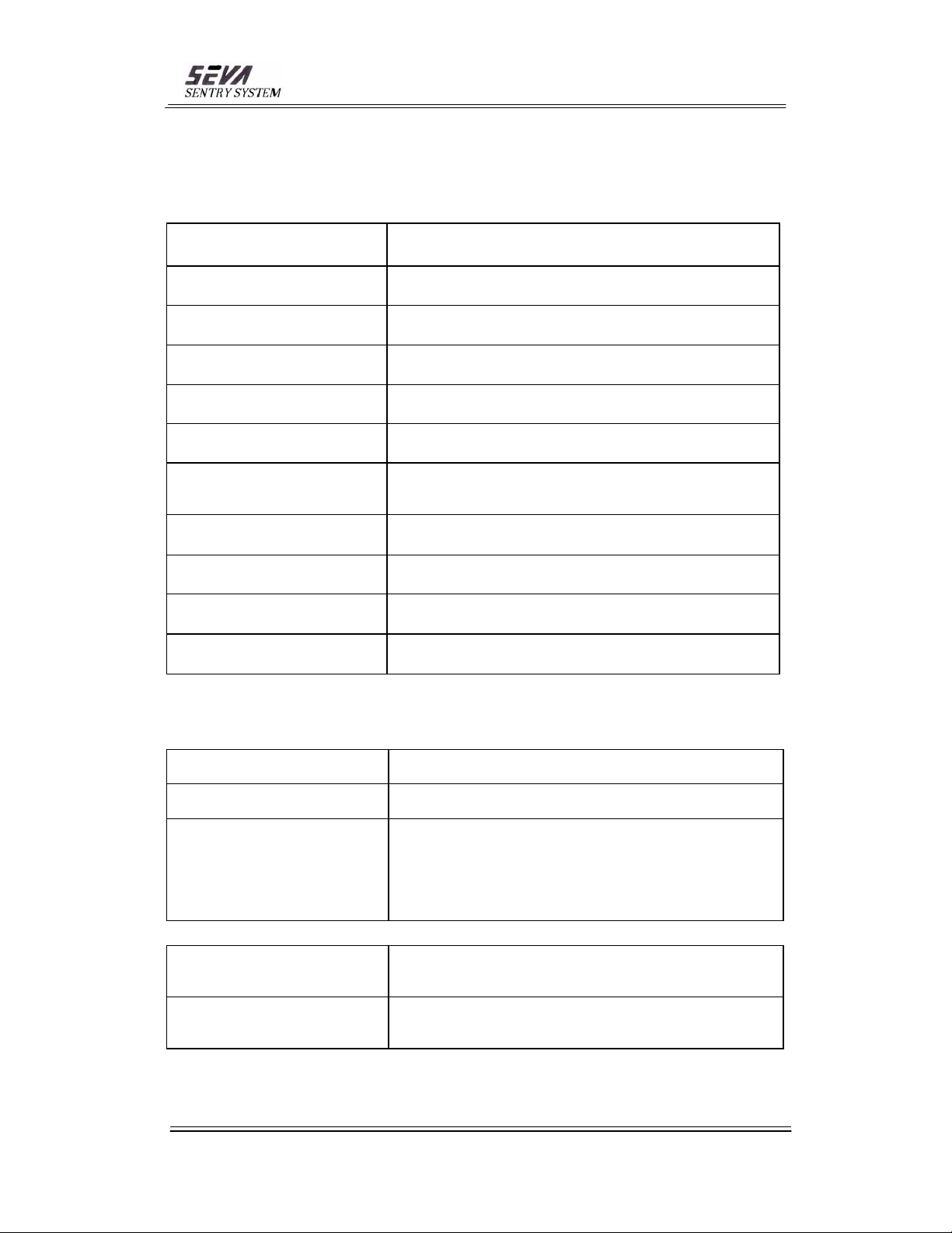
8. SPECIFICATIONS
8-1. TECHNICAL SPECIFICATION
Operating Temperature From -17C to +50C (form 0F to 122F)
Humidity To 95% non-condensing
Power Supply
Alarm Audible and visual alarm
Sensitivity Adjustment 12 Levels
Calibration
Interference Rejection
Masking
Construction
Throughput Minimum 60 people per minute
Warranty One year for electronic part.
100~260 Volts AC with 50/60Hz
Power consumption : 45W
FCC approved
Meet NILECJ-0601
100% sensor coil shielded by conductive shielding
Specially built-in circuitry for noise suppression
Special hardware to filter noise
Special program to cancel the effect caused by different metal
objects
Reinforced fiber glass.
Scratch resistant lamination
8-2 PHYSICAL SPECIFICATION
Outline Dimension
Passageway Dimension
Shipping Dimension
42.5" x 88" x 21.7"
(1080 x 2235 x 550mm)
33.5" x 80" x 13.4"
(850 x 2030 x 340mm)
Box1 : 87.8" x 17" x 8.5"
(2230 x 440 x 215mm)
Box2 : 41" x 16" x 18"
(1050 x 415 x 465mm)
Box3 : 18.5" x 14" x 11.6"
( 470 x 365 x 295mm)
Net
Weight
Shipping Weight
Box1 : 59.6 lbs ( 27kg )
Box2 : 30 lbs ( 13.5kg )
Box3: 18.8 lbs ( 8.5kg )
Box1 : 72.8 lbs ( 33kg )
Box2 : 37.5 lbs ( 17kg )
Box3 : 21 lbs ( 9.5kg )
- 20 -
Bangsan Technologies Inc.Sentry SystemSEVA
Page 21
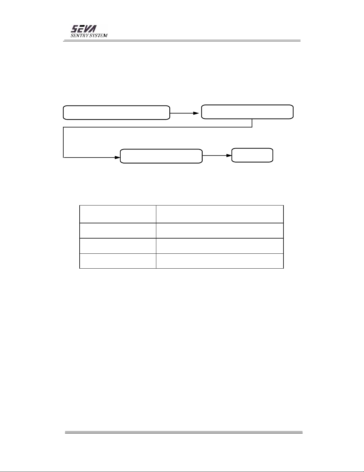
9. TEST
9-1 Program Setting
Function Key 4 Tim es UP/D O W N Key
Function Key 4 Tim es UP/D O W N Key
#1 LED ON
#1 LED ON
9-2 Test Condition
SPEED 1.0 M/S
SET
SET
Belt Equipped
Watch Equipped
Shoes Equipped
- 21 -
Bangsan Technologies Inc.Sentry SystemSEVA
Page 22
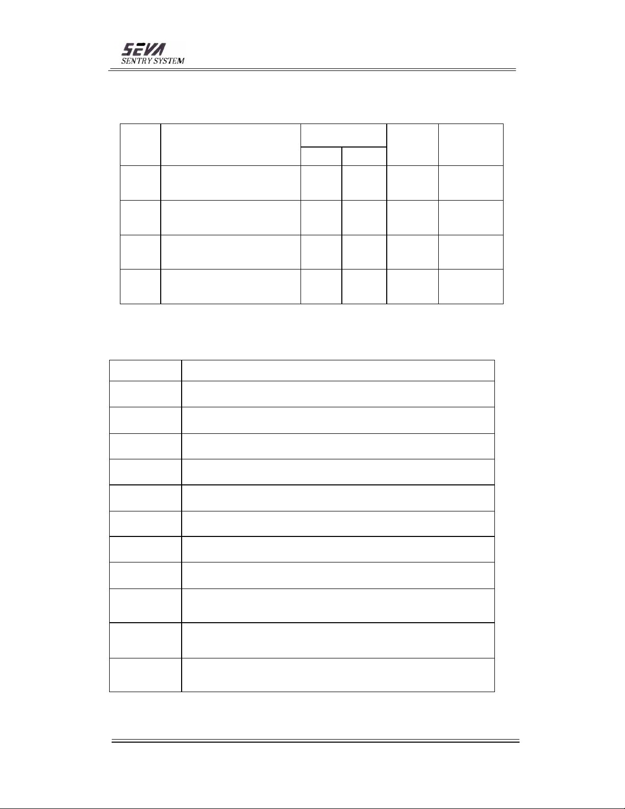
9-3 Test Pieces
Ref. Name of Gun
Dimensions
in(mm)
Length Height
Weight
lb(g)
Material
CS-40
910
317
SW99
Smith&Wesson CS-40
.40 S&W Chiefs Special
Smith&Wesson Model 910
9mm
Smith&Wesson 317
.22 Long Rifle AirLite
Smith&Wesson Model SW99
9mm
6.5(165) 5.3(135) 1.51(686)
7.4(187) 5.4(138) 1.75(794)
6.2(157) 4.3(110) 0.74(337)
7.1(180) 5.7(145) 1.59(720)
Ref. Detail
Coin
30 Coins (100)
Key 20 Keys (Standard Door key)
Cell Phone #1 Anycall SCH-A8100 (BTL1018S Battery Pack )
Cell Phone #2 LG-LDP-Cell phone 880 (Big Battery Pack)
Aluminum,
Stainless Steel
Aluminum,
Carbon Steel
Aluminum,
Stainless Steel
Polymer
Frame,
Stainless Steel
Cell Phone #3 Panasonic-KX-T 9200 KR (KX-A45 Battery Pack)
Beer Can
Hair Spray
Beer Can (Aluminum) (65Φ x 120mm)
Hair Spray Can (Steel) (45Φ x 210mm)
Knife Knife (Stainless steel, length closed : 13Cm)
Test Gun Test Gun (Garrett)
Accessory #1 Ladies Metal Accessory #1 (Steel)
Accessory #2 Ladies Metal Accessory #2 (Aluminum)
- 22 -
Bangsan Technologies Inc.Sentry SystemSEVA
Page 23
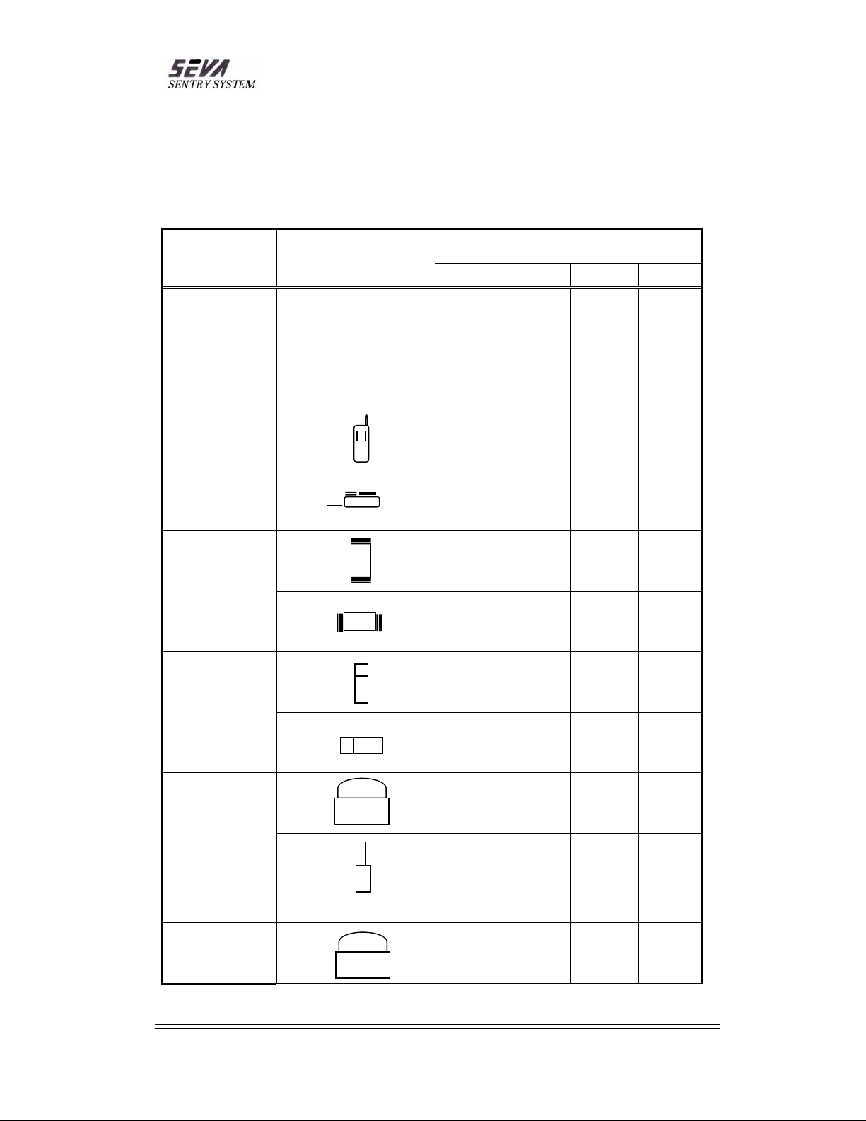
9-4 Test Result
O : Checked X : Not Checked OX : Often Checked
# Below result is the combination of 9 test
S E N S I T I V I T Y L
Test Piece Orientation
1 5 9 12
Coin X X X X
Key X X X X
X X X X
Cell Phone
#1
X X X X
E V E L
Beer Can
Hair Spray
All
together
(Coins ,
Keys
Cell phone
#2
Accessory
#1
Beer Can)
All
together
(Coins ,
X X X X
X X X X
X X X X
X X X X
X X X X
X X X X
X X X X
- 23 -
Bangsan Technologies Inc.Sentry SystemSEVA
Page 24
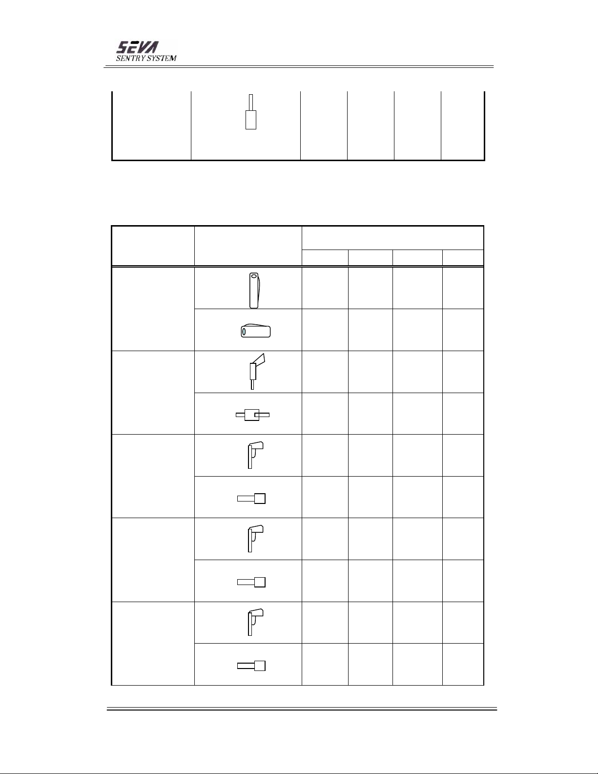
Keys
Cell phone
#3
Accessory
X X X X
#2 Hair
Spray)
O : Checked X : Not Checked OX : Often Checked
# Below result is the combination of 9 test
S E N S I T I V I T Y L
Test Piece Orientation
1 5 9 12
X X X X
Knife
X X X X
X X OX OX
E V E L
Test Gun
Gun CS-40
Gun 910
Gun 317
X OX OX OX
O O O O
O O O O
O O O O
O O O O
OX O O O
X OX OX O
- 24 -
Bangsan Technologies Inc.Sentry SystemSEVA
Page 25
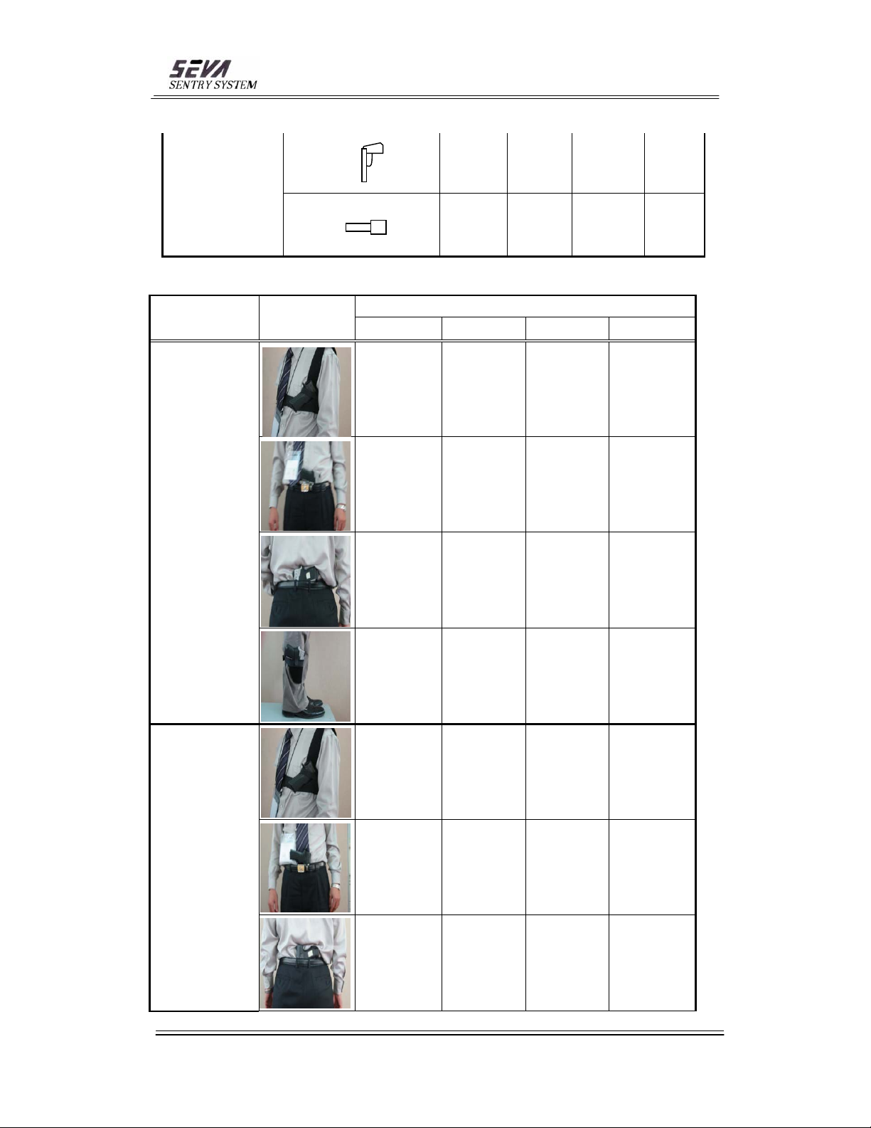
X OX O O
Gun SW99
# Results are based on the weapon orientation shown on photo
Test Piece
Gun CS-40
Orientati
on
O O O O
S E N S I T I V I T Y L E V E L
1 5 9 12
O O O O
O O O O
O O O O
Gun 910
O O O O
O O O O
O O O O
O O O O
Bangsan Technologies Inc.Sentry SystemSEVA
- 25 -
Page 26
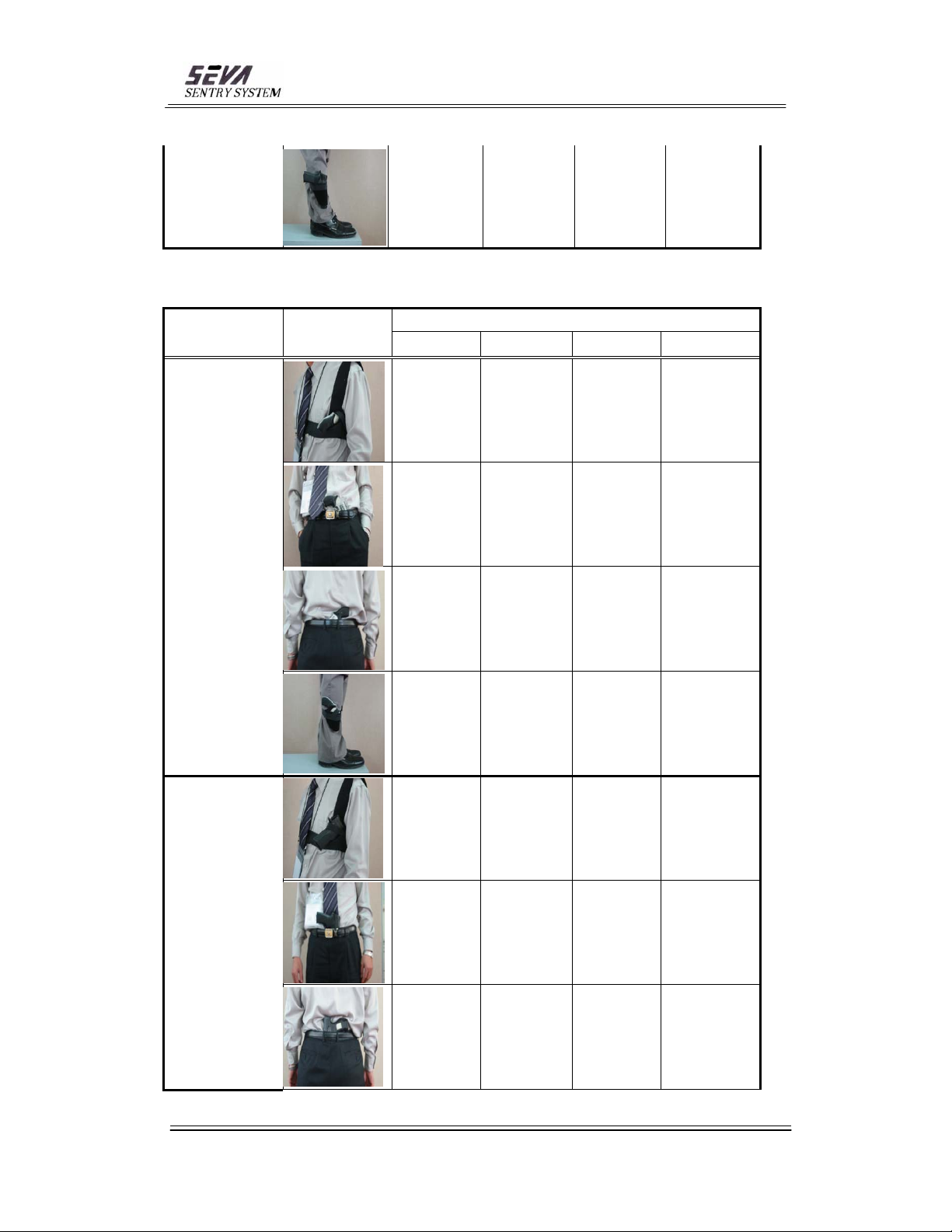
# Results are based on the weapon orientation shown on photo
Test Piece
Orientati
on
O O O O
S E N S I T I V I T Y L E V E L
1 5 9 12
X O O O
X O O O
Gun 317
Gun SW99
X O O O
X O O O
X O O O
X O O O
X O O O
Bangsan Technologies Inc.Sentry SystemSEVA
- 26 -
Page 27
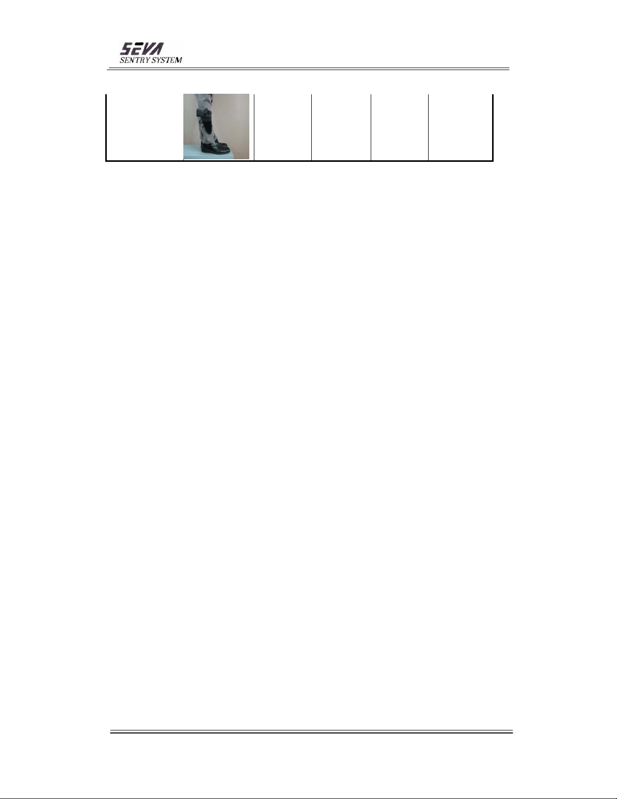
X X O O
- 27 -
Bangsan Technologies Inc.Sentry SystemSEVA
 Loading...