

Page 1

Settop
M1
USER MANUAL
v
.2 (Ma
rch
2018
)
Page 2

SETTOPSURVEY, S.L. Bofarull 14, 08027 Barcelona (Spain) Phone: (+34) 93 340 05 73 Fax: (+34) 93 351 95 18 www.settopsurvey.com info@settopsurvey.com
2
Index
ABOUT SETTOP M1 ......................................................................................................................................... 4
RECEIVER FUNCTIONS .................................................................................................................................. 5
FEATURES AND SPECIFICATIONS SETTOP M1 .......................................................................................... 6
GPS/GNSS ................................................................................................................................................. 6
COMMUNICATIONS .................................................................................................................................. 7
COMMUNICATION PORTS ....................................................................................................................... 7
ELECTRICAL AND OPERATING REQUIREMENTS ................................................................................ 8
SIZE AND WEIGHT.................................................................................................................................... 8
SCHEME SETTOP M1 ...................................................................................................................................... 9
F
RONT VIEW
.................................................................................................................................................... 9
B
ACK VIEW
.................................................................................................................................................... 12
U
PPER VIEW
.................................................................................................................................................. 13
RECEIVER INSTALLATION ........................................................................................................................... 14
W
EATHER CONDITIONS
................................................................................................................................... 14
E
XTERNAL ANTENNA LOCATION
....................................................................................................................... 14
BATTERIES AND POWER ............................................................................................................................. 15
P
OWERING TO SETTOP
M1 ............................................................................................................................. 15
P
OWERING TO OTHER DEVICES
........................................................................................................................ 16
CONFIGURING THE RECEIVER ................................................................................................................... 17
D
EFAULT SETTINGS
........................................................................................................................................ 17
T
URN ON SETTOP
M1 ..................................................................................................................................... 18
Configuring via Wi-Fi ................................................................................................................................ 18
Configuring via PHONE ............................................................................................................................ 18
S
OURCES OF ELECTRICAL INTERFERENCE
........................................................................................................ 19
C
ONFIGURING THE RECEIVER USING WEB INTERFACE
....................................................................................... 20
System Status .......................................................................................................................................... 21
System configuration ................................................................................................................................ 23
APPENDIX I - EXAMPLES OF CONFIGURATION ........................................................................................ 46
S
IMPLE BASE MODE
....................................................................................................................................... 47
R
OVER MODE
................................................................................................................................................ 49
R
EFERENCE BASE FOR INFRASTRUCTURE MODE
.............................................................................................. 52
M
ARITIME JOBS MODE
.................................................................................................................................... 55
C
ONTROL CENTER MONITORING / MONITORING MODE
..................................................................................... 57
C
ENTRE MODE CONTROL FOR DYNAMIC CONTROLS
........................................................................................ 58
G
UIDED MODE CONTROL OF CRANES
.............................................................................................................. 60
APPENDIX II - FAQ (FREQUENTLY ASKED QUESTIONS) ......................................................................... 62
W
HAT TO DO IF THE RECEIVER DOES NOT TURN ON
. .......................................................................................... 62
S
ATELLITE
LED
DOES NOT LIGHT UP
................................................................................................................ 62
T
HE TOTAL STATION IS NOT RESPONDING
......................................................................................................... 62
T
HE TOTAL STATION IS NOT LINKED
.................................................................................................................. 62
I
USE WINDOWS
8.1,
CAN I CONNECT WITH SETTOP
M1? .................................................................................. 62
APPENDIX III - ACCESSORIES AND OPTIONS ........................................................................................... 64
Page 3

SETTOPSURVEY, S.L. Bofarull 14, 08027 Barcelona (Spain) Phone: (+34) 93 340 05 73 Fax: (+34) 93 351 95 18 www.settopsurvey.com info@settopsurvey.com
3
Page 4

SETTOPSURVEY, S.L. Bofarull 14, 08027 Barcelona (Spain) Phone: (+34) 93 340 05 73 Fax: (+34) 93 351 95 18 www.settopsurvey.com info@settopsurvey.com
4
About Settop M1
The Settop M1 is a GNSS reference receiver with remote control for Total Stations. It allows you to
manage GPS data while carrying out surveying work with a Total Station through various communication
ports such as Wi-Fi, Bluetooth, Radio, Ethernet and GSM. Its flexibility and versatility makes the M1 the
standard reference model in surveying applications. The hardware has been designed with the aim of
making the M1 the smallest and lightest device on the market and fully configurable by customers.
The GPS RTK receiver is configurable as Base, Rover and Caster with emission and reception of
differential corrections via Radio, Internet Wi-Fi and Bluetooth. It is also configurable via web interface.
You can control and store Total Station data and internal GPS for surveying work.
It is configurable as Caster for sending differential corrections to different customers simultaneously via
telephone equipment. External devices can be controlled via a connection to its communication ports
(temperature sensors, pressure, inclinometers etc.).
Page 5

SETTOPSURVEY, S.L. Bofarull 14, 08027 Barcelona (Spain) Phone: (+34) 93 340 05 73 Fax: (+34) 93 351 95 18 www.settopsurvey.com info@settopsurvey.com
5
Receiver Functions
Settop M1 features are many and their versatility is very high. It can be configured as:
•
Simple Base: With the possibility of sending differential corrections by radio and telephone integrated systems
(CASTER).
•
Rover: You can receive differential corrections by radio or telephone, with an integrated battery or installed in a
backpack.
•
Infrastructure Reference Base: With the ability to mount it as a fixed base transmitting differential corrections by
radio, mobile and wireless with active caster.
•
Equipment for marine works: With the possibility of mobile equipment configuration, synchronization PPS
output with hydro-graphic equipment (echo sounder, etc.).
•
Control Centre monitoring / static monitoring: With the ability to record GPS data in internal memory for post-
processing, and to receive real-time corrections from GPS and from any total stations connected that are carrying out
measurements of the area being controlled. You can also send data over the Internet
•
Control Centre for dynamic control, especially for bridges and / or installation of platforms, combined with the
right software to view the item's position in real time via Internet.
•
Control guide for cranes: this allows the placement of blocks and, combined with the right software, allows you
to view their position in real time with the serial data output and online.
All specifications and explanations relating to GNSS solutions are included only in SETTOP M1 when
GPS/GNSS board is installed
Page 6

SETTOPSURVEY, S.L. Bofarull 14, 08027 Barcelona (Spain) Phone: (+34) 93 340 05 73 Fax: (+34) 93 351 95 18 www.settopsurvey.com info@settopsurvey.com
6
Features and specifications Settop M1
The Receiver Settop M1 has the following features:
GPS/GNSS
•
220 Channels:
GPS: Simultaneous L1 C/A, L2E,L2C, L5
GLONASS: Simultaneous L1 C/A, L1 P, L2 C/A (GLONASS M Only), L2 P
SBAS: Simultaneous L1 C/A, L5
Galileo: Simultaneous L1 BOC, E5A, E5B, E5AltBOC1 (optional)
BeiDou: B1, B2 (optional)
QZSS: L1 C/A, L1 SAIF, L2C, L5 (optional)
•
Advanced Trimble Maxwell 6 Custom Survey GNSS Technology
•
High precision multiple correlator for GNSS pseudo-range
•
Unfiltered, unsmoothed pseudo-range measurements data for low noise, low multipath error, low time
domain correlation and high dynamic response
•
Very low noise GNSS carrier phase measurements with <1mm precision in a 1 Hz bandwidth
•
Signal-to-Noise ratios reported in dB-Hz
•
Proven Trimble low elevation tracking technology
Initialization time2…………………………..typically <10 seconds
Initialization reliability2………………………> 99.9 %
•
1 Hz, 2 Hz, 5 Hz, 10 Hz, 20 & 50 Hz positioning outputs (depends on installed option)
•
Up to 50 Hz raw measurement & position outputs
Reference outputs……………………………………….. CMR+, RTCM 3.08
Navigation outputs………………………………………..ASCII: NMEA-0183 GSV, AVR, RMC, HDT,
VGK, VHD, ROT , GGK, GGA, GSA, ZDA , VTG, GST, PJT, PJK, BPQ, GLL, GRS, GBS & Binary:
Trimble GSOF
•
Position Specification
1 Developed under a License of the European Union and the European Space Agency.
2 May be affected by atmospheric conditions, signal multipath, and satellite geometry. Initialization reliability is continuously monitored to ensure highest quality.
4 At maximum output rate.
5 GPS only and depends on SBAS System performance. FAA WAAS accuracy specifications are <5 m 3DRMS.
6 Dependent on appropriate mounting/enclosure design
7 Input only network correction.
8 Typical observed values
9 No previous satellite (ephemerides / almanac) or position (approximate position or time) information.
10 Ephemerides and last used position known
11 As required by the U.S. Department of Commerce to comply with export licensing restrictions
Mode
Accuracy
4
Latency
5
Maximum
Rate
Single Base Line
(<30Km)
8mm + 1ppm Hz / 15mm + 1ppm Vt <20 ms 50 Hz
DGPS 0.25m + 1ppm Hz / 0.50m +1ppm Vt <20 ms 50 Hz
SBAS
6
< 5m 3D <20 ms 50 Hz
Page 7

SETTOPSURVEY, S.L. Bofarull 14, 08027 Barcelona (Spain) Phone: (+34) 93 340 05 73 Fax: (+34) 93 351 95 18 www.settopsurvey.com info@settopsurvey.com
7
COMMUNICATIONS
Radio Module
•
Bandwidth:
390 - 430 MHz or
430 - 470 MHz
•
Frequency Control
•
Synthesized 12.5 kHz resolution setting
•
Frequency Stability ± 1 ppm
•
12.5/25 kHz Channel Spacing (detectable)
•
RF Transmitter Output
•
w (RX-only) & 0.1-1 w (Programmable)
•
Sensibility:
-110 dBm VER = 1 x 10⁻⁵
•
Adjacent Channel Sensitivity:
55 dB
•
Certification type
All models are accepted and certified to operate in the U.S., Australia and Canada FCC, IC, EU, NZ,
Australia ETS300-113-2
GSM HSDPA modem (3,5G)
Option A
•
Dual Band UMTS: 900 / 2100 MHz (EU3-E)
•
Tri-Band UMTS: 850 / 900 / 2100 MHz (EU3-P)
•
Dual Band GSM: 900 / 1800 MHz
•
HSDPA data: DL : max. 3.6 Mbps, UL: max. 384 kbps
•
UMTS data: DL: max. 384 kbps, UL: max. 384 kbps
•
EDGE data: DL: max. 237 kbps, UL: max. 118 kbps
•
GPRS data: DL: max. 86 kbps, UL: max. 43 kbps
•
GSM/CSD data transmission: 14.4 kbps
Option B
•
Five-Bands UMTS/HSPA+ (WCDMA/FDD) (800/850/900/1900/2100 MHz)
•
Quad-Band GSM (850/900/1800/1900 MHz)
•
HSDPA Cat.10 / HSUPA Cat.6 data rates DL: max. 14.4 Mbps, UL: max. 5.76 Mbps
•
EDGE Class 12 data rates DL: max. 237 kbps, UL: max. 237 kbps
•
GPRS Class 12 data rates DL: max. 85.6 kbps, UL: max. 85.6 kbps
•
CSD data transmission 14.4 kbps, V.110
Wi-Fi
•
IEEE 802.11b/g
Bluetooth
•
2.0 + ERD (Enhanced Data Rate) wireless technology.
COMMUNICATION PORTS
•
1 RS232/USB Host Event port, PPS Power In/Out
•
2 RS232/USB OTG port Power In/Out
•
1 TNC connector for GPS antenna
•
1 TNC connector for radio antenna
•
1 FME connector for GSM antenna
•
1 Slot SIM card
•
1 Slot MicroSD card
Page 8

SETTOPSURVEY, S.L. Bofarull 14, 08027 Barcelona (Spain) Phone: (+34) 93 340 05 73 Fax: (+34) 93 351 95 18 www.settopsurvey.com info@settopsurvey.com
8
ELECTRICAL AND OPERATING REQUIREMENTS
•
External Power: 12 – 30V AC.
•
Power:
All components activated at full power: 12.8W
•
Operating temperature -40º a 75º C
•
Storage temperature -55º a 85º C
•
Random vibe MIL-STD 810F (7.7g RMS)
•
Vibe SAEJ1211 (4g)
•
Bump/Shock IEC 68-2-27 (30g)
•
IP67
SIZE AND WEIGHT
•
1 Front Panel with 10 LED status indicators
•
Size:
Width: 13.8 cm
Depth: 13.8 cm
•
Height: 3.5 cm
•
Weight: 0.6Kg
Page 9
SETTOPSURVEY, S.L. Bofarull 14, 08027 Barcelona (Spain) Phone: (+34) 93 340 05 73 Fax: (+34) 93 351 95 18 www.settopsurvey.com info@settopsurvey.com
9
Scheme Settop M1
For a good understanding of the equipment, please study the following diagrams
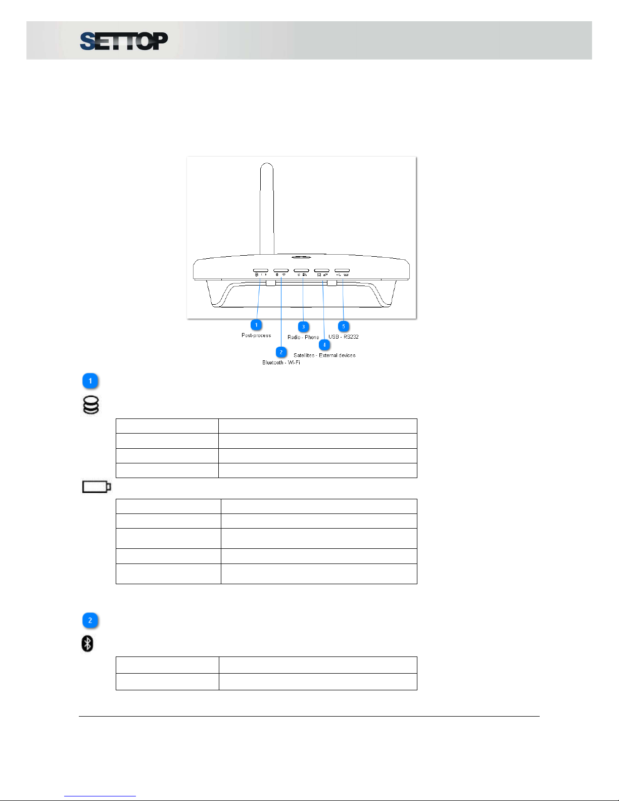
Front View
Post-process
Post-process (Green LED)
Status
Action
Turned Off Doesn't store data
Constant flashing 1s Storing data
Fixed Full memory
Power (Red LED)
Status
Action
Turned Off Not connected
Flashing fast and
continuous
Low battery
Fixed Turned on
Flashing (1) every
10s
Standby*
*
Power on unit, but unit is turned off
Bluetooth - Wi-Fi
Bluetooth (Green LED)
Status
Action
Turned Off Not linked to any device
Page 10
SETTOPSURVEY, S.L. Bofarull 14, 08027 Barcelona (Spain) Phone: (+34) 93 340 05 73 Fax: (+34) 93 351 95 18 www.settopsurvey.com info@settopsurvey.com
10
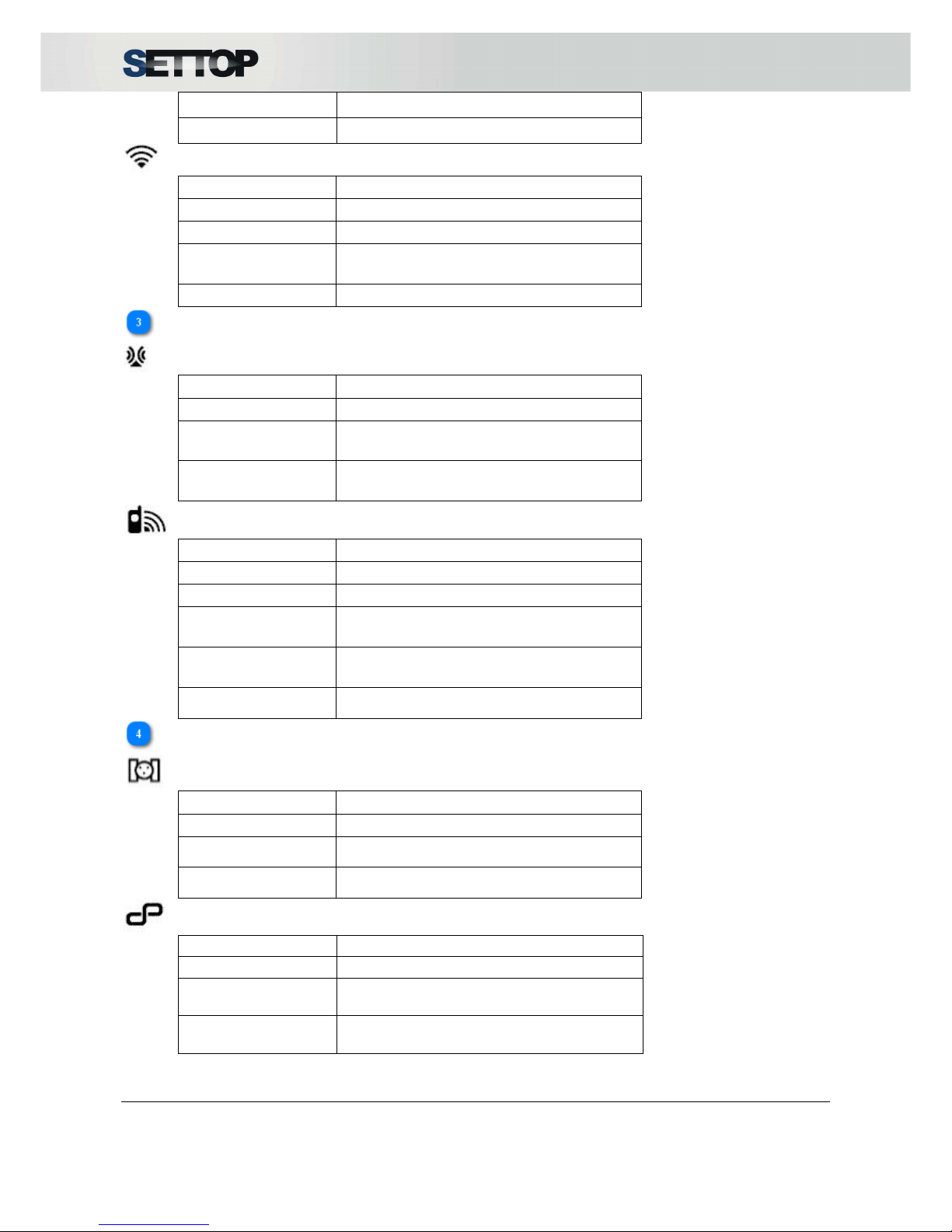
Flashing light Linking to a device
Fixed Device linked
Wi-Fi (Red LED)
Status
Action
Turned Off Not linked to any network
Modulated light Looking for a network Wi-Fi
Constant flashing
(2 per second)
AD-HOC Mode
Fixed Network linked
Radio - Phone
Radio (Green LED)
Status
Action
Turned Off Doesn’t use radio
Constant flashing
(1 per second)
Radio signal transmitting (e.g. Mode Base)
Constant flashing
(2 per second)
Radio signal receiving (e.g. Mode Rover)
Phone (Red LED)
Status
Action
Turned Off Doesn’t use phone
Fixed Doesn’t have SIM CARD
Constant flashing
(1 per second)
GPRS Coverage
Constant flashing
(2 per second)
HSDPA Coverage
Constant rapid
flashing
Error
Satellites - External devices
Satellites (Green LED)
Status
Action
Turned Off Not receiving Satellites
Flashing “n”
constant flashes
Receiving “n” Satellites
Constant rapid
flashing
Error
External devices (Red LED)
Status
Action
Turned Off Device not linked
Constant flashing
(1 per second)
Total Station linked via USB
Constant flashing
(2 per second)
Total Station linked via bluetooth
Page 11
SETTOPSURVEY, S.L. Bofarull 14, 08027 Barcelona (Spain) Phone: (+34) 93 340 05 73 Fax: (+34) 93 351 95 18 www.settopsurvey.com info@settopsurvey.com
11
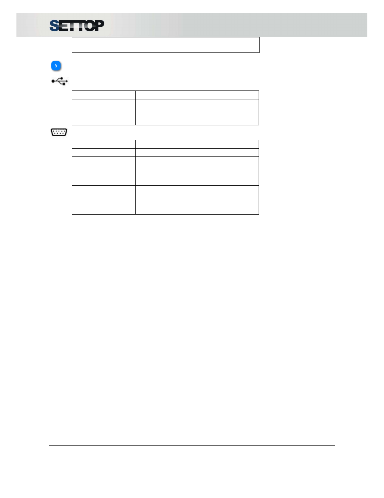
Constant flashing
(3 per second)
Station connected via cable and bluetooth
USB - RS232
USB (Green LED)
Status
Action
Turned Off Device Disconnected
Constant flashing
(2 per second)
Device connected via USB in LEMO 2
RS232 (Red LED)
Status
Action
Turned Off Device disconnected
Constant flashing
(1 per second)
Device connected via RS232 in LEMO1
Constant flashing
(2 per second)
Device connected via RS232 in LEMO2
Constant flashing
(3 per second)
Device connected via RS232 in LEMO1 and
LEMO 2
Constant flashing
(1 Hz)
Service mode
Page 12
SETTOPSURVEY, S.L. Bofarull 14, 08027 Barcelona (Spain) Phone: (+34) 93 340 05 73 Fax: (+34) 93 351 95 18 www.settopsurvey.com info@settopsurvey.com
12
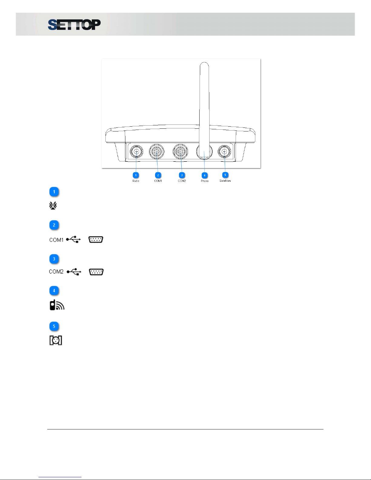
Back View
Radio
Radio antenna connector
COM1
Lemo connector for RS232/ power in
COM2
Lemo connector for USB / power in/out (RS232 with adapter cable)
Phone
GSM Antenna connector
Satellites
GPS Antenna connector
Page 13
SETTOPSURVEY, S.L. Bofarull 14, 08027 Barcelona (Spain) Phone: (+34) 93 340 05 73 Fax: (+34) 93 351 95 18 www.settopsurvey.com info@settopsurvey.com
13
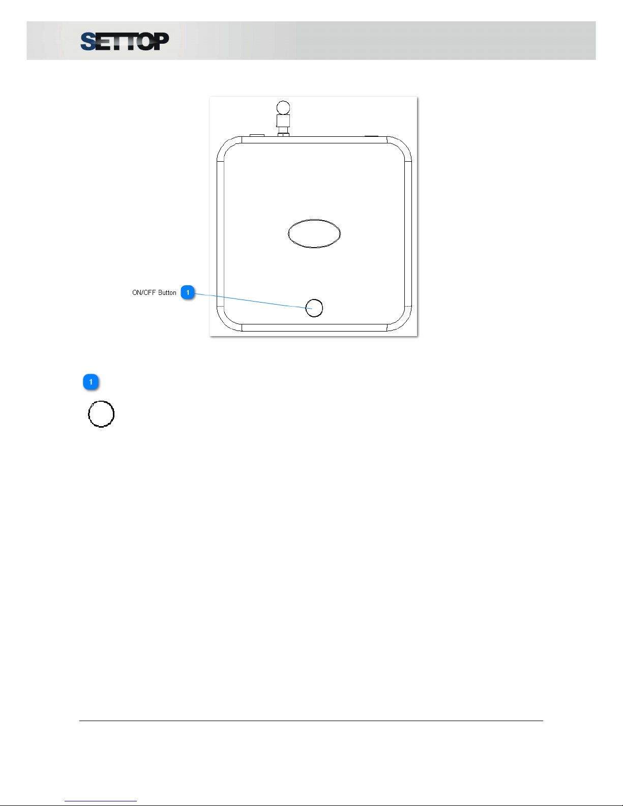
Upper View
ON/OFF Button
1. Turn on the device by pressing the button.
2. AD-HOC Mode ON (3 taps on the button, force temporal AD-HOC). When the receiver is turned on.
3. Turn off the device by pressing the button for a few seconds, until the leds are flashing fast.
Page 14

SETTOPSURVEY, S.L. Bofarull 14, 08027 Barcelona (Spain) Phone: (+34) 93 340 05 73 Fax: (+34) 93 351 95 18 www.settopsurvey.com info@settopsurvey.com
14
Receiver Installation
Weather conditions
The equipment is conforms to environment rating (IP67), which makes it dust-proof and protects it against
contact with solids and liquids and makes it able to withstand pressure and water leakage when the unit is
submerged to a maximum of 1m.
However, you must take reasonable care to keep the unit dry.
To improve the performance and long-term reliability of the receiver avoid exposing the receiver to extreme
environmental conditions, such as:
•
Water
•
Heat: above 75 ° C
•
Cold: less than -40 ° C
•
Liquids and corrosive gases
External Antenna location
Before mounting the antenna on the reference station, you should carefully plan where to locate the antenna
and think how you will be able get precise coordinates.
You should choose a place which is as free as possible from interference, where the antenna has a clear
view of the sky and where there are no obstructions above the elevation of 10°.
If there are obstacles above 10°, or large metal objects nearby, the rover can collect data from satellites that
the reference station cannot pick up. These data cannot be used in DGPS RTK rover or solutions.
Page 15
SETTOPSURVEY, S.L. Bofarull 14, 08027 Barcelona (Spain) Phone: (+34) 93 340 05 73 Fax: (+34) 93 351 95 18 www.settopsurvey.com info@settopsurvey.com
15
Batteries and Power
Powering to Settop M1
The receiver uses an external power source. If the receiver is not connected to an external power source or
if the external power supply fails, the receiver will shut down automatically without storing the data and
controlling external devices. The data that has been stored will not be lost. W hen the external power source
is restored, the computer will boot automatically with the last settings loaded. Autopower option must be
enabled (ON) in the System Settings section.
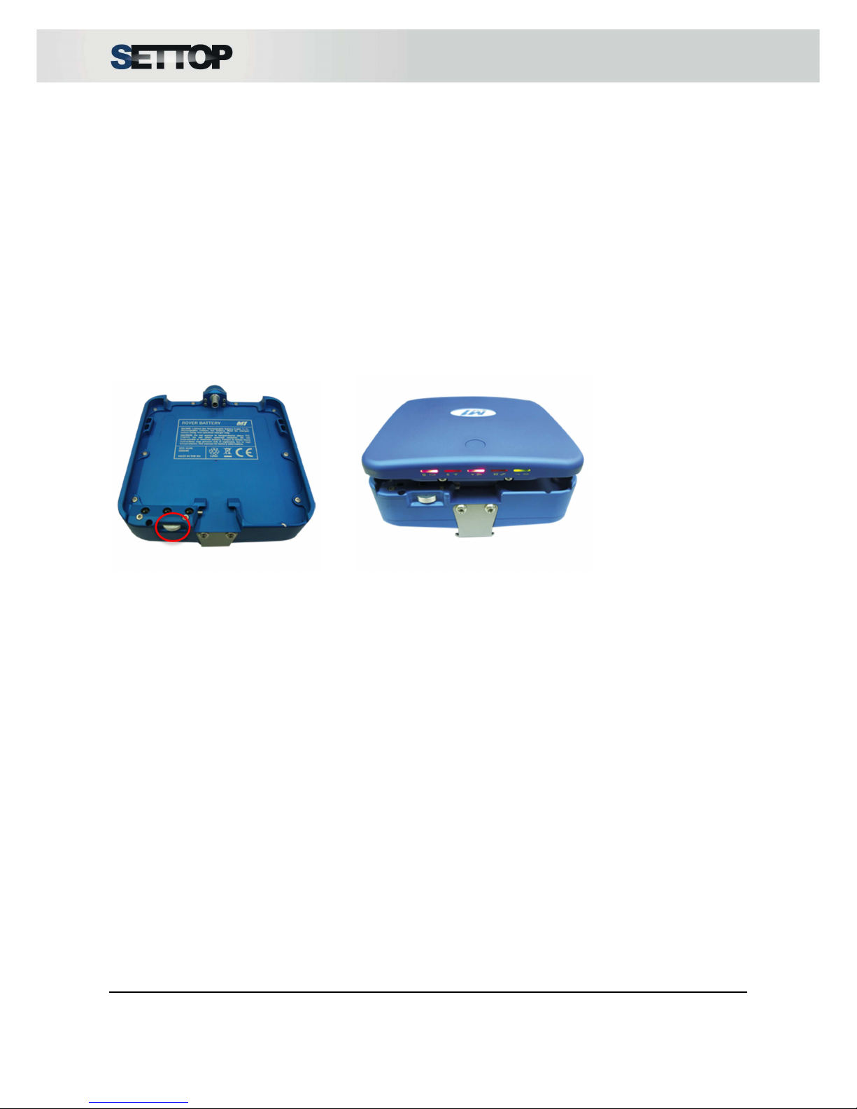
The battery supplied with the receiver Settop M1 is a rechargeable 12V NiMH Settop 9Ah which allows
continuous operation for up to 8 hours and with a special integrated battery the Settop M1 receivers capacity
increases to 14Ah that allows the unit to work continuously for more than 13 hours. Also, to ensure continuity
of operation it can be connected to the mains transformer with 12V - 32V.
You must press the button (red circle) for attaching and detach the battery and M1.
Page 16

SETTOPSURVEY, S.L. Bofarull 14, 08027 Barcelona (Spain) Phone: (+34) 93 340 05 73 Fax: (+34) 93 351 95 18 www.settopsurvey.com info@settopsurvey.com
16
Powering to other devices
Settop M1 can power other devices connected through the COM1 or COM2 slots. To do so, System Settings
must indicate on the bridge option the limit of power supply you want, cutting off at the time of peak indicated.
Power limits are 15V, 20V, 25V and 30V.
The bridge is configured in both directions, that is, from COM1 to COM2 and COM2 to COM1.
WARNING: Before you activate the bridge, make sure that the computer can receive the maximum
voltage setting. Improper use of this option, can damage the computer, leaving it unusable.
Page 17

SETTOPSURVEY, S.L. Bofarull 14, 08027 Barcelona (Spain) Phone: (+34) 93 340 05 73 Fax: (+34) 93 351 95 18 www.settopsurvey.com info@settopsurvey.com
17
Configuring the receiver
Default settings
The Settop M1 receiver comes with a default configuration to start a job easily.
The configuration of SETTOP M1 default state is:
•
Main user
Username: admin *
Password: m1
*Note: This user is for web interface and caster services.
•
Configured as a GPS Rover
•
Station not connected
•
Wi-Fi configured in AD-HOC
IP Address: 192.168.2.2
IP Ethernet Adapter: 192.168.11.89
DHCP Server: Enabled
•
Bluetooth without any link
•
Telephone not configured
•
Radio:
Protocol: Trimtalk450s,
Channel: 1 – 433075 Hz,
Sensitivity: High sensitivity
Power: 1W
•
System:
Autopower: off
Bridge: off
Language: English
Page 18

SETTOPSURVEY, S.L. Bofarull 14, 08027 Barcelona (Spain) Phone: (+34) 93 340 05 73 Fax: (+34) 93 351 95 18 www.settopsurvey.com info@settopsurvey.com
18
Turn on Settop M1
When you received SETTOP M1 for the first time, it is necessary to set a minimum setting. You can follow
this setting Step by Step:
Configuring via Wi-Fi
•
Step 1:
Connect Power Cable (Ref. 310508) in COM 1 or COM2, or internal battery (Ref. M1-Rover-Battery)
•
Step 2:
Press the ON/OFF button and wait until the OS Boots Up. Wi-Fi LED flashes modulate (see diagram in
section 1.4 Settop M1 Scheme) when searching for a network and Wi-Fi LED flash 2 times per second when
it is in adhoc mode. If the receiver has been misconfigured and wants to reconfigure in ad-hoc mode, you
must press the ON/OFF button for 3 times.
•
Step 3:
With a PC, iPhone or iPad with Wi-Fi Access, press “search network”. It will appear as one network called
“Settop M1 SN” (SN is a serial number).
•
Step 4:
Enter Network password “adhoc”.
•
Step 5:
Open your Internet browser (it supports Google Chrome and Safari) and key in IP address 192.168.2.2
•
Step 6:
User name is: admin
Password: m1
Configuring via PHONE
•
Step 1:
Connect Power Cable (Ref. 310508) in COM 1 or COM2, or internal battery (Ref. M1-Rover-Battery)
•
Step 2:
Press the ON/OFF button and wait until the OS Boots Up. Phone LED flashes constantly (one or two times
per second) (see diagram in section 1.4 Settop M1 Scheme).
•
Step 3:
With a PC, iPhone or iPad, open your Internet browser (it supports Google Chrome and Safari) and key in
static IP address assigned at SIM card.
•
Step 4:
User name is: admin
Password: m1
NOTE: If you use a Windows 8.1, you need to configure your operating system (see FAQ - I use
Windows 8.1, can I connect with Settop M1? )
Page 19

SETTOPSURVEY, S.L. Bofarull 14, 08027 Barcelona (Spain) Phone: (+34) 93 340 05 73 Fax: (+34) 93 351 95 18 www.settopsurvey.com info@settopsurvey.com
19
Sources of electrical interference
High power signals from a nearby radio or radar transmitter can overwhelm the receiver circuits. This does
not harm the instrument, but can prevent the electronic receiver from working properly.
Avoid placing the receiver or antenna at least 400 meters from the following sources of electricity and / or
magnetic noise:
•
Powerful Radar
•
Gasoline engines (spark plugs)
•
TVs and computer monitors
•
GNSS antennas.
•
Alternators and generators
•
Electric motors
•
Equipment with DC-AC converters
•
Fluorescent lights
•
Switching power supplies
Low-power transmitters such as cell phones and two-way radios normally do not interfere with the operation
of the receiver.
It is recommended that you use an uninterruptible power supply (UPS) to power the receiver. A UPS protects
equipment from surges and spikes, and keeps the receiver operating during power outages of short duration.
For more information, contact Settop Survey (support@settopsurvey.com).
Page 20
SETTOPSURVEY, S.L. Bofarull 14, 08027 Barcelona (Spain) Phone: (+34) 93 340 05 73 Fax: (+34) 93 351 95 18 www.settopsurvey.com info@settopsurvey.com
20
Configuring the receiver using web interface
The software of the Settop M1 has been designed as a web application. This means that no type of software
installation is necessary on the computer and you only have to connect to its interface web via a local
network or via Internet and you can interact with the application. The user interface is really easy to use and
supplies the user with all the information he needs about his instrument by simply turning on the application.
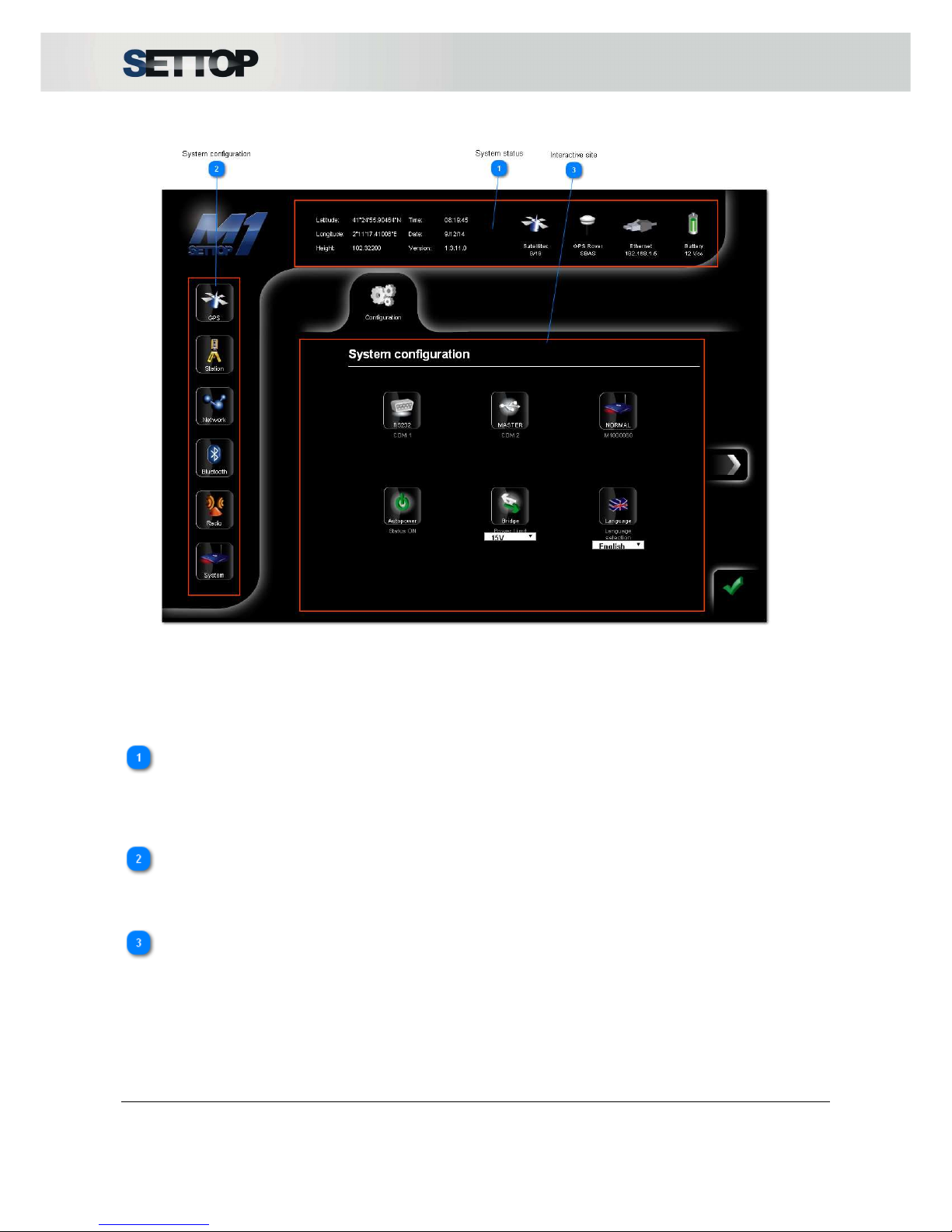
The web is divided into three basic parts: information about the system (System status), configuration of the
system (System configuration) and interactive site.
System status
In the upper part, we can control the state of the configuration of our Base/Mobile GPS as well as its
autonomous/floating/ fixed/post-process state. To configure our instrument we only have to select the device
that we want to modify and all possible configurations will appear in the centre frame of the screen.
System configuration
Moving the icons on the left, we can control at all times the configuration of our equipment as well as the
events that are happening on the job.
Interactive site
In the central part, is all the space to interact and configure your receiver using the option that allows the
device to operate. The OK button validates the settings done at the time.
Page 21
SETTOPSURVEY, S.L. Bofarull 14, 08027 Barcelona (Spain) Phone: (+34) 93 340 05 73 Fax: (+34) 93 351 95 18 www.settopsurvey.com info@settopsurvey.com
21
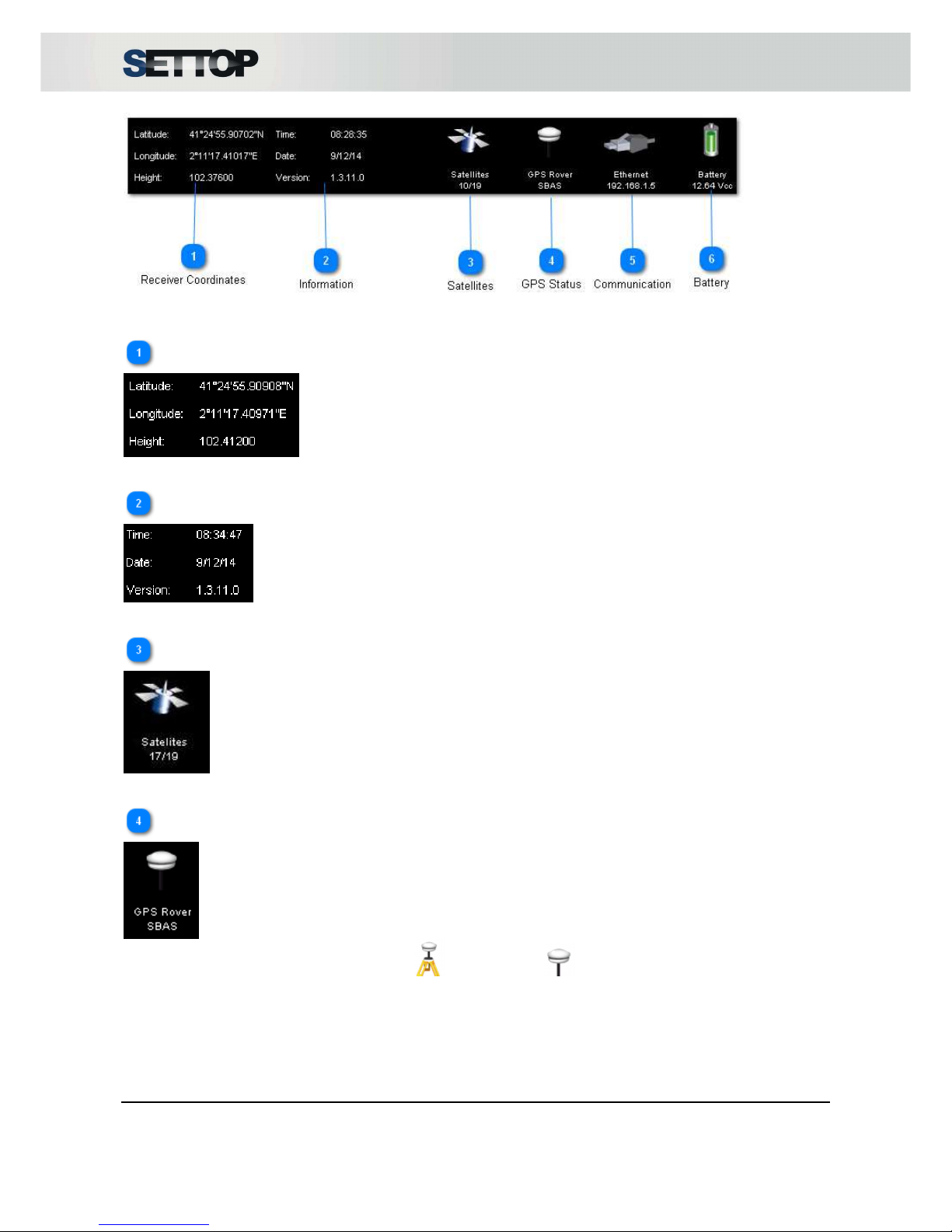
System Status
The top bar in the browser, informs us of the current settings of the receiver SETTOP M1.
Receiver Coordinates
In the first part of the bar, we can look at the coordinates received in WGS84
Information
In the second column, appears date, time and firmware installed.
Satellites
Number of satellites received and used are shown
GPS Status
Configuration mode information (Base mode or Rover mode )
Status level: Autonomous, SBAS, RTK Floating or RTK Fixed
Page 22

SETTOPSURVEY, S.L. Bofarull 14, 08027 Barcelona (Spain) Phone: (+34) 93 340 05 73 Fax: (+34) 93 351 95 18 www.settopsurvey.com info@settopsurvey.com
22
Communication
The third picture indicates used communication method. Ethernet, Wi-Fi and mobile phone. For W i-Fi and
mobile phone, it also shows the coverage level (see Network).
Battery
The battery symbol indicates voltage level received for the receiver
The battery levels are divided into 5 states ranging from 0% to 100%
Battery
level:
0% 1-25% 25-50% 50-75% 75-100%
NOTE: In a state of continuous power, the voltage will remain stable.
Page 23

SETTOPSURVEY, S.L. Bofarull 14, 08027 Barcelona (Spain) Phone: (+34) 93 340 05 73 Fax: (+34) 93 351 95 18 www.settopsurvey.com info@settopsurvey.com
23
System configuration
You can configure the main features of Settop M1 via the side menu. Each icon will indicate with graphical
features the status of your device configuration.
GPS Settings
1. Configuration
In the first tab of GPS, are chains of NMEA data output. These can be configured to output 1Hz, 2Hz, 5Hz,
10Hz, 50Hz, 1s, 2s, 5s depending on the user need.
The output sync pulse per second (PPS) is made through port 1.
Page 24

SETTOPSURVEY, S.L. Bofarull 14, 08027 Barcelona (Spain) Phone: (+34) 93 340 05 73 Fax: (+34) 93 351 95 18 www.settopsurvey.com info@settopsurvey.com
24
GPS data can be received through this option:
COM Port 1: 115.200bps, 8, n, 1
TCP/IP Port: 20.000
Bluetooth: 115.200 bps
The common settings for the GNSS receiver that will be present in all other sections are:
•
Selecting and tracking constellations (WAAS, GLONASS, L2C)
•
Model Selection of antenna height measurement method
•
Elevation mask and PDOP mask.
Display the Skyplot (distribution of satellites in the sky and signal intensity) and SkyTable (satellite list and
information of these)
Page 25

SETTOPSURVEY, S.L. Bofarull 14, 08027 Barcelona (Spain) Phone: (+34) 93 340 05 73 Fax: (+34) 93 351 95 18 www.settopsurvey.com info@settopsurvey.com
25
Page 26

SETTOPSURVEY, S.L. Bofarull 14, 08027 Barcelona (Spain) Phone: (+34) 93 340 05 73 Fax: (+34) 93 351 95 18 www.settopsurvey.com info@settopsurvey.com
26
2. Post process
This option allows you to save files for GNSS post processing. Internal memory available is 1GB.
By pressing ON, starts to save a new file. By pressing OFF, it stops the record file. Before starting a new
postprocessing session the user needs to select if old files will be deleted automatically when memory is full.
If we choose Delete automatically it will delete the older file existing in memory, although if the option
selected Do not delete automatically, it will stop the record when memory is full.
Also, it is possible to choose Observable time records and Position time every 1s, 2s, 5s, 10s, 15s, 30s or
60s
In Base mode, every hour it generates a new file with RT27 logs. The name is
M10000SN_DDDH_YYYY.rt27, where:
•
SN: Serial Number
•
DDD: Day of the year (001, 002, 003, etc.)
•
H: Hour of the day (A, B, C, etc.)
•
YYYY: Year
In Rover mode it generates a new file like M10000SN_YYMMDD_N.rt27, where:
•
SN: Serial Number
•
YY: Year
•
MM: Month
•
DD: Day
•
N: Number of Rover postprocessing files of the day
Page 27

SETTOPSURVEY, S.L. Bofarull 14, 08027 Barcelona (Spain) Phone: (+34) 93 340 05 73 Fax: (+34) 93 351 95 18 www.settopsurvey.com info@settopsurvey.com
27
By pressing File management it shows a list of stored files. Here you can download the selected files by
pressing or delete the file by pressing .
By pressing Delete files, it cleans all files recorded and pressing Format file system it cleans the memory and
it formats again the internal memory.
Page 28

SETTOPSURVEY, S.L. Bofarull 14, 08027 Barcelona (Spain) Phone: (+34) 93 340 05 73 Fax: (+34) 93 351 95 18 www.settopsurvey.com info@settopsurvey.com
28
3. Caster
The Server service is always active since the SETTOP M1 is configured as Base. The transmit formats are
CMR +, RTCM 3.0 and RT27. Users can connect through the IP and port specified with the username and
password (default user: admin and pswd: m1)
Settop M1 can manage up to 8 users connected at the same time. To add and manage users you should go
to System → Manage.
To connect to a network as a Client, you need to enter the IP and Port. The IP must be numeric
(xxx.xxx.xxx.xxx). The username and password provided by the server/administrator.
By pressing List, it shows all the mount points available and when the user presses ON, it starts to receive
corrections.
The TCP / IP option Broadcaster allows data transmission to another computer via internet. Protocols
supported are RTCM3.0, CMR+ and RT27)
When the broadcaster is OFF, the user can modify IP, Port and select the mountpoint.
When the broadcaster is ON, IP, Port and mountpoints are blocked.
Page 29

SETTOPSURVEY, S.L. Bofarull 14, 08027 Barcelona (Spain) Phone: (+34) 93 340 05 73 Fax: (+34) 93 351 95 18 www.settopsurvey.com info@settopsurvey.com
29
4. Rover
The option GPS Rover allows use of the SETTOP M1 as a rover receiver and use its features (see
Examples of Configuration).
Settop M1 in Rover Mode receives automatically CMR+, RTCM2.3 and RTCM3.0 corrections.
By pressing will store a point. The number will increase in one unit and it will show coordinates
(Lat/Long/Elev), date and time. You can download ASCII file with stored points (IP/points.txt).
Basic set up for Rover mode:
•
Constellations and tracking selection (WAAS, GLONASS, L2C)
•
Antenna, height and measurement selection
•
Elevation mask and PDOP mask
•
Skyplot (satellites distribution and signal intensity) and Skytable (satellites information list)
Page 30

SETTOPSURVEY, S.L. Bofarull 14, 08027 Barcelona (Spain) Phone: (+34) 93 340 05 73 Fax: (+34) 93 351 95 18 www.settopsurvey.com info@settopsurvey.com
30
Page 31

SETTOPSURVEY, S.L. Bofarull 14, 08027 Barcelona (Spain) Phone: (+34) 93 340 05 73 Fax: (+34) 93 351 95 18 www.settopsurvey.com info@settopsurvey.com
31
5. Base
Option Base mode, allows you to configure SettopM1 for transmitting differential corrections through radio or
internet.
For setting up the receiver, you need to introduce the name and the coordinates in WGS84, may be geodetic
(Lat, Long, Elev) or projected UTM (East, North, Elevation). If you don’t know the coordinates of the control
point, you can press Here and the coordinates fields will be filled automatically.
If the Settop M1 receives corrections from another Base or Caster, is possible configure our receiver in Fixed
position before to press Here for an optimum configuration of the system coordinates. This system can
extend the distance between bases.
By pressing , Settop M1 starts to transmit the corrections.
In Rover mode the default configurations are as follows:
•
Constellations and tracking selection (WAAS, GLONASS, L2C)
•
Antenna, height and measurement selection
•
Elevation mask and PDOP mask
•
Skyplot (satellites distribution and signal intensity) and Skytable (satellites information list)
Page 32

SETTOPSURVEY, S.L. Bofarull 14, 08027 Barcelona (Spain) Phone: (+34) 93 340 05 73 Fax: (+34) 93 351 95 18 www.settopsurvey.com info@settopsurvey.com
32
Page 33

SETTOPSURVEY, S.L. Bofarull 14, 08027 Barcelona (Spain) Phone: (+34) 93 340 05 73 Fax: (+34) 93 351 95 18 www.settopsurvey.com info@settopsurvey.com
33
Total Station Settings
The Settop M1 can be connected to a total station Trimble S8 with Finelock, either via USB cable.
Once the devices are connected, the control of the TS for monitoring is carried out via external software. You
can consult Settop Survey (support@settopsurvey.com) for the most suitable software for your needs.
To control the TS via a cable connection, you can use a USB cable. The distance between the Settop M1
and the TS should not exceed the length of the cable (1.5 m approx.). The cable plugs into the hirose 6-pin
connector to the COM port of the TS and the USB connector on the specified port for it in the Settop M1
(COM2).
When a device is connected, an icon appears on the side of the serial number. Also, the green background
of the serial number indicates connection to the computer. With a white background, the station is linked but
not connected.
One Total Station can be connected over USB
“Automatic Power supply Management” checkbox allows Settop M1 to automatically manage the Total
Station power (suggested for monitoring tasks)
Monitoring Option (NO GNSS board installed)
COM1 of the Settop M1 is used to connect RS232 devices to be remotely controlled and with an IP address
and a port. You can select the baud rate of the device to which you will connect.
Page 34

SETTOPSURVEY, S.L. Bofarull 14, 08027 Barcelona (Spain) Phone: (+34) 93 340 05 73 Fax: (+34) 93 351 95 18 www.settopsurvey.com info@settopsurvey.com
34
When tab with SN (serial number) is printed in green, communication is OK.
Page 35

SETTOPSURVEY, S.L. Bofarull 14, 08027 Barcelona (Spain) Phone: (+34) 93 340 05 73 Fax: (+34) 93 351 95 18 www.settopsurvey.com info@settopsurvey.com
35
Network Settings
Network configuration has three interfaces that appear in the top horizontal bar, Modem, Wi-Fi, Ethernet:
Modem Wi-Fi Ethernet
1. Modem
The data required to configure internet access via the phone are the APN, username and password.
The intensity of the signal from the telephone network data transfer is shown at five levels ranging from 0%
(gray) to 100% (blue) regardless of the technology used.
In the horizontal top bar, you can see the technology used and the coverage level. GPRS (2G), EDGE (2.5
G), UMTS (3G), HSDPA (3.5 G).
Page 36

SETTOPSURVEY, S.L. Bofarull 14, 08027 Barcelona (Spain) Phone: (+34) 93 340 05 73 Fax: (+34) 93 351 95 18 www.settopsurvey.com info@settopsurvey.com
36
Coverage
level
0% 1-25% 26-50% 51-75% 76-100%
2. Wi-Fi
To configure the wireless network of Settop M1 you have to choose from the available options. The first
parameter to look for is the network name (ESSID), the type of encryption can be WEP, WPA or nothing at
all, the mode can be DHCP (IP automatically assigned by the router) or static (you must configure the IP,
subnet mask and gateway.
To apply the settings you must press . It has a control system which indicates if a required field is
missing. If it is not consistent in this area, this field is marked in red.
Page 37

SETTOPSURVEY, S.L. Bofarull 14, 08027 Barcelona (Spain) Phone: (+34) 93 340 05 73 Fax: (+34) 93 351 95 18 www.settopsurvey.com info@settopsurvey.com
37
The Scan button tracks all available activated networks within reach of the Settop M1. All of these networks
appear in a list and you can select one by double clicking on it; it is then pre-set and you only need to
introduce the password.
The Back arrow allows you to return to the original set that you had before making changes.
The intensity of the wireless network signal is shown at four levels ranging from 0% (white) to 100% (blue) in
the horizontal top bar.
Page 38

SETTOPSURVEY, S.L. Bofarull 14, 08027 Barcelona (Spain) Phone: (+34) 93 340 05 73 Fax: (+34) 93 351 95 18 www.settopsurvey.com info@settopsurvey.com
38
Intensity
level:
0-25 % 25-50 % 50-75 % 75-100%
Adhoc
The Settop M1 has an IP assigned 192.168.2.2 and connected device has an IP assigned in the range of
192.168.2.xxx
Page 39

SETTOPSURVEY, S.L. Bofarull 14, 08027 Barcelona (Spain) Phone: (+34) 93 340 05 73 Fax: (+34) 93 351 95 18 www.settopsurvey.com info@settopsurvey.com
39
3. Ethernet
You can connect Settop M1 with an Ethernet cable and an adapter.
You can select the mode within Static or DHCP. If the selection is Static, you must configure the IP, Net
Mask and Gateway.
If mode selection is DHCP the configuration is automatic
Page 40

SETTOPSURVEY, S.L. Bofarull 14, 08027 Barcelona (Spain) Phone: (+34) 93 340 05 73 Fax: (+34) 93 351 95 18 www.settopsurvey.com info@settopsurvey.com
40
Bluetooth Settings
The Bluetooth connection will allow a wireless control of the Total Station, the maximum connection distance
is around 10m.
To synchronize Settop M1 with a Total Station we must go to the Bluetooth section and link the device. This
is done by pressing Scan new Device and selecting one from the list. To be assigned, press Assign devices.
This is then immediately added to the list of linked devices. Only total stations (TS) will appear in section TS
with their serial numbers.
Devices can be unlinked by activating the checkbox and pressing Delete selected devices.
Page 41

SETTOPSURVEY, S.L. Bofarull 14, 08027 Barcelona (Spain) Phone: (+34) 93 340 05 73 Fax: (+34) 93 351 95 18 www.settopsurvey.com info@settopsurvey.com
41
Radio Settings
The configuration of the radio allows you to choose between Protocol, Channel, Sensitivity, Power and type
of corrections,
Eligible protocols:
•
Transparent w EOT timeout
•
Transparent w EOT character
•
Packet switched
•
TrimMark II / IIe
•
TrimTalk 450S
•
SATEL
•
TT450 S (HW)
•
TrimMark 3
The radio channels should be in the frequency range from 390 to 430 MHz or between 430 to 470 MHz,
depending on the radio model and geographic location.
The sensitivity should be set depending on what you are going to give the Settop M1. High sensitivity is
recommended for jobs like configuring Rover and low sensitivity when working as Base.
Power can be 0.1, 0.5 and 1W.
Output types are CMR+ or RTCM3.0
NOTE: All USA users, must check the CSMA setting
Page 42

SETTOPSURVEY, S.L. Bofarull 14, 08027 Barcelona (Spain) Phone: (+34) 93 340 05 73 Fax: (+34) 93 351 95 18 www.settopsurvey.com info@settopsurvey.com
42
System Configuration
In the System section there are two subsections that show the Settop M1 configuration.
The first subsection indicates the “status” of the receiver, indicating the connection method on COM1 and
COM2 ports and if they can be connected via RS232 , USB (Master).
The second part indicates the settings options that are configurable.
When the option Auto power is set to OFF , the device does not automatically turn on when the power
supply is connected.
If Auto power is set to ON the device will automatically turn on when the power supply is connected.
Below the icon is the current configuration. To change it, you have to press OK.
Bridge is the option to power other devices connected to COM1 or COM2 from Settop M1, it should
indicate the maximum power. In the event of exceeding this limit, the power is cut off. This limit can be 15V,
20V, 25V and 30V.
NOTE: In monitoring applications the voltage is fixed to 15V.
Page 43

SETTOPSURVEY, S.L. Bofarull 14, 08027 Barcelona (Spain) Phone: (+34) 93 340 05 73 Fax: (+34) 93 351 95 18 www.settopsurvey.com info@settopsurvey.com
43
The bridge is set up to operate from either COM1- COM2 or COM2 – COM1.
To activate the bridge it is necessary to press OK.
The red arrow icon indicates that the bridge is not activated .
The Language option allows you to select English or Spanish language. The change is not made until you
press OK.
On the second screen of the system setup, there are internal options that are only available to qualified
technical service.
Update
Option: Used to update the Settop M1 to the latest firmware.
By pressing Check for a new version it connects to Settop Upgrade Servers and if there is some new version
available it will start to download the latest firmware.
Page 44

SETTOPSURVEY, S.L. Bofarull 14, 08027 Barcelona (Spain) Phone: (+34) 93 340 05 73 Fax: (+34) 93 351 95 18 www.settopsurvey.com info@settopsurvey.com
44
After downloading the latest version. The unit must be rebooted
If there aren’t new versions it appears a message
SAT
Option: This is reserved for Technical Service. You must enter a password to access
Page 45

SETTOPSURVEY, S.L. Bofarull 14, 08027 Barcelona (Spain) Phone: (+34) 93 340 05 73 Fax: (+34) 93 351 95 18 www.settopsurvey.com info@settopsurvey.com
45
Internal
Option: This is reserved for Technical Service. You must enter a password to access
Manage
Option: Allows user management system. User may change the username and password
of the administrator of the Settop M1. You can also manage usernames and passwords for caster users
(create and delete users).
Reboot
Option: Closes all routines, turns off the receiver and turns it on again.
Page 46

SETTOPSURVEY, S.L. Bofarull 14, 08027 Barcelona (Spain) Phone: (+34) 93 340 05 73 Fax: (+34) 93 351 95 18 www.settopsurvey.com info@settopsurvey.com
46
APPENDIX I - Examples of Configuration
The following section is intended to give some basic guidelines and tips on how to assemble and configure
the Settop M1 in a few simple steps for the various utilities for which it was designed. These
recommendations are only in order to get a basic idea of the potential of Settop M1.
NOTE: The configurations listed below are examples of how to configure the equipment.This doesn’t
mean that this is the only way to configure the system. The final configuration is the decision of the user.
Page 47

SETTOPSURVEY, S.L. Bofarull 14, 08027 Barcelona (Spain) Phone: (+34) 93 340 05 73 Fax: (+34) 93 351 95 18 www.settopsurvey.com info@settopsurvey.com
47
Simple Base Mode
For the simple base configuration the following accessories are necessary:
•
External GPS Antenna
•
Antenna Cable
•
Tribrach
•
Extension
•
Tripod
•
Settop integrated battery or external battery
You can use the internal communication modules (either the modem or telephony radio module) to transmit
the signal to the other rover receivers.
After installing the base in the desired location, you proceed to configure it through the computer or mobile
device with Wi-Fi. You can also connect to another controller (via Bluetooth), but in this case it would be an
external control software.
Once in the GPS section and the GPSBase mode, enter the base name and enter the coordinates.
Geodetic (GG.gggggg) or UTM (Easting, Northing, Height, Zone) coordinates can be entered. If you don't
Page 48

SETTOPSURVEY, S.L. Bofarull 14, 08027 Barcelona (Spain) Phone: (+34) 93 340 05 73 Fax: (+34) 93 351 95 18 www.settopsurvey.com info@settopsurvey.com
48
know the precise coordinates, you can press the button Here to automatically enter the field coordinates
giving an accuracy of 1-2 meters (depending on the location, satellites number, etc). If could previously
connect to another base or caster and the receiver is in RTK Fixed, the accuracy will be better. The accuracy
of the base you set will be given by the received corrections.
To finish the setting, you must select the antenna type and height.
Pressing OK will accept the settings and the equipment will start to transmit on the frequency and format
selected in Radio tab. Automatically it will generate a caster offering RTCM and CMR+, to connect through
the Internet
A very common Radio example:
•
Protocol: TrimTalk 450S
•
Sensitivity: Low
The channel and power depend on the environment in which the Settop M1 is to be located.
After setting up, base icon will appear in the top bar of the current configuration, with the number of satellites
being received at this time.
Page 49

SETTOPSURVEY, S.L. Bofarull 14, 08027 Barcelona (Spain) Phone: (+34) 93 340 05 73 Fax: (+34) 93 351 95 18 www.settopsurvey.com info@settopsurvey.com
49
Rover Mode
For use as rover configuration the following accessories are necessary:
•
External GPS Antenna
•
Antenna Cable
•
Range pole
•
Battery integrated Settop
Or
•
Bag / Backpack for transporting the receiver Settop M1
•
External Battery
In the same way as in the base configuration, you will benefit from the internal communication modules
available (radio or telephone modem) to receive the corrections sent through a reference or base station.
You can use the connection to the computer or controller with external software to store data. Also, you can
store data pressing Accept and you can visualize all data if you press Survey Data. After that, you can
download the file.
Page 50

SETTOPSURVEY, S.L. Bofarull 14, 08027 Barcelona (Spain) Phone: (+34) 93 340 05 73 Fax: (+34) 93 351 95 18 www.settopsurvey.com info@settopsurvey.com
50
When using the web interface you only need to select the antenna type and key in the height and press OK
to start receiving corrections supported by the Settop M1 (which are: CMR, CMR +, RTCM 2.3, RTCM 3.0. )
via the radio.
A common radio configuration if you are using a rover mode is:
•
Protocol: TrimTalk 450S
•
Sensitivity: High
The channel and power also depend on how you configured the Base
If you have a SIM card for GPRS data download (rates depends on the contract with the operator) in the M1
receptor, can receive corrections via NTRIP protocol. To do this, we must firstly go to Caster Settings.
In Client, we introduce the numerical value of IP and Port. If necessary a username and password
(provided by the service manager) must be entered in the appropriate boxes.
Page 51

SETTOPSURVEY, S.L. Bofarull 14, 08027 Barcelona (Spain) Phone: (+34) 93 340 05 73 Fax: (+34) 93 351 95 18 www.settopsurvey.com info@settopsurvey.com
51
Next, press List to list the available mount points on the server. Mountpoint is selected and you press ON. If
all parameters are correct, the selected point on green, if there is an error (usually username and / or
password) the mountpoints will appear in red.
Once you are receiving the appropriate corrections, we can go to tab GPS Rover.
Page 52

SETTOPSURVEY, S.L. Bofarull 14, 08027 Barcelona (Spain) Phone: (+34) 93 340 05 73 Fax: (+34) 93 351 95 18 www.settopsurvey.com info@settopsurvey.com
52
Reference Base for infrastructure mode
For installation as a baseline for infrastructure you need the following accessories:
•
External antenna GPS
•
Antenna Cable (Long)
•
External radio antenna
•
Cable radio (Long)
•
UPS
For the configuration of a reference base station it is necessary to ensure continuous power to the Settop M1.
The specified ports to receive power are COM1. The GPS antenna should be placed on the top of the
building and at an “open” site to ensure optimum satellite reception. An external radio antenna is also
necessary to ensure radio coverage in the defined area. The distance between the Settop M1 and the GPS
antenna or radio antenna should not be further than 30m because the quality of the signal declines. Both
antennas are connected to the corresponding connectors.
Through the web interface you can access the base section:
Page 53

SETTOPSURVEY, S.L. Bofarull 14, 08027 Barcelona (Spain) Phone: (+34) 93 340 05 73 Fax: (+34) 93 351 95 18 www.settopsurvey.com info@settopsurvey.com
53
Once in the GPS section and GPSBase mode, enter the database name and load the coordinates, where
they are already known. Geodetic format can be entered (GG.gggggg) or UTM (Easting, Northing, Height,
Zone). If you don’t know the precise coordinates, you can press the button Here and the coordinates will
appear automatically with an accuracy of 1-2 meters.
By pressing OK you will accept the settings and the equipment will then be transmitting on the frequency
selected and the selected format in paragraph Radio.
A very common radio setting to use in Simple Base mode is:
•
Protocol: TrimTalk 450S
•
Sensitivity: None or Low
The channel and power depend on the environment in which the Settop M1 is located.
Once the base set appears in the top bar of the current configuration, with the number of satellites currently
receiving. To take full advantage of a Reference Station as Settop M1, it is advisable that the machine's IP is
static.
Page 54

SETTOPSURVEY, S.L. Bofarull 14, 08027 Barcelona (Spain) Phone: (+34) 93 340 05 73 Fax: (+34) 93 351 95 18 www.settopsurvey.com info@settopsurvey.com
54
In this way, users can always connect to the same IP and port without configuring the computer every time it
reboots. Transmission formats are CMR+ and RTCM 3.0
With the baseline already configured, data can be sent over the Internet to another computer located in the
headquarters of the company, for example. To do this, you should go to Caster option and enable IP ports of
those hosts.
Page 55

SETTOPSURVEY, S.L. Bofarull 14, 08027 Barcelona (Spain) Phone: (+34) 93 340 05 73 Fax: (+34) 93 351 95 18 www.settopsurvey.com info@settopsurvey.com
55
Maritime Jobs Mode
To use a Settop M1 for marine works you will need the following accessories:
•
External Antenna
•
Antenna Cable
•
UPS / External Battery
•
Cable PPS output
•
Sounder
•
Transducer
To set the receiver Settop M1 for maritime works you must ensure continuous supply, either through an
integrated battery Settop M1, an external battery NiMH or a power supply.
The GPS antenna needs to be connected to the vertical transducer and fastened securely to the boat.
The echo sounder will be connected through the COM1 or COM2 ports with the special cable with PPS
output. The computer is connected via the COM that is free.
Through M1 webservice, go to Configuration GPS and configure the following strings NMEA: GGA, ZDA,
VTG (these strings are used depending on the software used) at 5Hz.
Page 56

SETTOPSURVEY, S.L. Bofarull 14, 08027 Barcelona (Spain) Phone: (+34) 93 340 05 73 Fax: (+34) 93 351 95 18 www.settopsurvey.com info@settopsurvey.com
56
A common radio configuration if you are using rover mode is:
•
Protocol: TrimTalk 450S
•
Sensitivity: High
The channel and power also depend on how you have configured the Base.
Another option to receive corrections with SETTOP M1 is connected as a client to a NTRIP caster and
entering the IP and port of the server, along with a username and password (if necessary) would get the
corrections by mobile phone.
Page 57

SETTOPSURVEY, S.L. Bofarull 14, 08027 Barcelona (Spain) Phone: (+34) 93 340 05 73 Fax: (+34) 93 351 95 18 www.settopsurvey.com info@settopsurvey.com
57
Control Center Monitoring / Monitoring Mode
For monitoring / static auscultation you need the following accessories:
•
External antenna GPS (if monitoring with GPS)
•
Antenna Cable.
•
Total Station.
•
UPS
To perform a static monitoring or continuous monitoring job it is necessary to ensure continuous power
supply to the receiver. To do this, connect the power supply into the COM1 or COM2 slot.
The connection with the total station is via COM 2 but can also be done via Bluetooth (see Connecting to the
Total Station) . We recommend using a cable connection because with a USB connection you can reset the
system if the system fails. Another difference between using the wireless or cable system is the number of
stations that can be controlled. While Bluetooth can control up to 4 stations, USB cable can only handle a
single total station but is a better option in case the system fails, as mentioned before.
In the case of GPS, corrections are also required. The antenna should be in a place with an “open sky” and
connected via antenna cable to the connector. The purpose of using a GPS is to discern whether the station
is in a zone of influence. It is not advisable to exceed the 30m distance between the antenna and the Settop
M1.
Through the web interface you can access the total station. If it is connected, the light appears in green (next
to the symbol used: Bluetooth or USB connection) and the control of the movements are performed through
external software, like TDCM (TDCM see Software Manual).
Page 58

SETTOPSURVEY, S.L. Bofarull 14, 08027 Barcelona (Spain) Phone: (+34) 93 340 05 73 Fax: (+34) 93 351 95 18 www.settopsurvey.com info@settopsurvey.com
58
Centre Mode Control for Dynamic Controls
A dynamic control is the monitoring of a structure / block must be located on a site and it can be used for
GPS or total stations. Depending on whether you are tracking with GPS or total station, it will take one or the
other components.
GPS
Total Station
Dynamic Monitoring with GPS
For dynamic monitoring you need the following accessories:
•
External antenna GPS (1 SETTOP M1 per antena)
•
Antenna Cable
To perform an monitoring or continuous monitoring job it is necessary to ensure continuous power supply to
the receiver. To do this, connect the power supply into the COM1. The antenna should be in a place with an
“open sky” and connected via antenna cable to the connector. The purpose of using a GPS is to discern
whether the station is in a zone of influence. It is not advisable to exceed the 30m distance between the
antenna and the Settop M1
To set up a dynamic monitoring with GPS, it is necessary to go to the GPS Rover tab. There you only need
to select the type of antenna and key in height and press OK to start receiving corrections supported by the
Settop M1 (they are: CMR, CMR +, RTCM 2.3, RTCM 3.0.) via the radio.
Page 59

SETTOPSURVEY, S.L. Bofarull 14, 08027 Barcelona (Spain) Phone: (+34) 93 340 05 73 Fax: (+34) 93 351 95 18 www.settopsurvey.com info@settopsurvey.com
59
A common radio configuration if you are working in rover mode is:
•
Protocol: Trimtalk
•
Sensitivity: High
It is possible that you will require more than one receiver Settop M1 for proper dynamic monitoring. It will
depend the points, antennas and stations to be controlled and the connection method used. Settings are the
same for the other receivers. Once the receivers are configured, we go to the external control software to
control the movements of the structure.
Dynamic Monitoring with Total Station
For dynamic monitoring you need the following accessories:
•
Total Station High Precision
•
USB cable
•
Targets
To perform an monitoring or continuous monitoring job it is necessary to ensure continuous power supply to
the receiver. To do this, connect the power supply into the COM1.
The connection with the total station is via port 2 but can also be done via Bluetooth (see section Connecting
to the Total Station). We recommend using cable connection because with a USB connection you can reset
the system if in the event of failure. Another difference between using the wireless or cable system is the
number of stations that can be controlled. While Bluetooth can control up to 4 stations, USB cable can only
handle a single total station.
Through the web interface you can access the total station. If it is connected, the light appears in green (next
to the symbol used: Bluetooth or USB connection) and the control of the movements are performed through
external software, like TDCM and the software for the structures.
Page 60

SETTOPSURVEY, S.L. Bofarull 14, 08027 Barcelona (Spain) Phone: (+34) 93 340 05 73 Fax: (+34) 93 351 95 18 www.settopsurvey.com info@settopsurvey.com
60
Guided Mode Control of Cranes
For placement of blocks with a crane you need the following accessories:
•
External antenna GPS
•
Antenna Cable 30m (For other cases consult your SETTOP Dealer)
For placing concrete blocks on certain sites with the precision that an RTK GPS generates you need the
GPS antenna position to be on top of the vertical boom crane. Also, the Settop M1 must be powered by an
external battery which is connected to COM1 or COM2.
Through the web interface, in order to access the section GPS Rover, you only need to select the type of
antenna and key in height and press OK to start receiving data corrections supported by the Settop M1
(which are: CMR, CMR +, RTCM 2.3, RTCM 3.0.) via the radio or NTRIP connection.
A common radio configuration if you are using rover mode:
•
Protocol: Trimtalk
•
Sensitivity: High
Page 61

SETTOPSURVEY, S.L. Bofarull 14, 08027 Barcelona (Spain) Phone: (+34) 93 340 05 73 Fax: (+34) 93 351 95 18 www.settopsurvey.com info@settopsurvey.com
61
The channel and power also depend on how you configured the Base.
An external software (like Hypack or GPSat (see software manual)), shows the location of the blocks that the
crane has to put in place.
Page 62

SETTOPSURVEY, S.L. Bofarull 14, 08027 Barcelona (Spain) Phone: (+34) 93 340 05 73 Fax: (+34) 93 351 95 18 www.settopsurvey.com info@settopsurvey.com
62
APPENDIX II - FAQ (Frequently Asked Questions)
LED indicators can provide information about possible problems with the Settop M1 receiver. A fast and
continuous flashing light indicates an error in the indicated part of the receiver.
What to do if the receiver does not turn on.
The first step to take is to check the power supply. First, check the battery and then check the cable,
particularly the plugs and see if you notice any defects or if one is missing. The third step is to check the
cable connection. Make sure the cable is connected properly, matching the red dot with the corresponding
point of the connector. Press the power button to turn on the receiver.
Satellite LED does not light up
Satellite LED is off, indicating no satellite reception. Make sure the power supply reaches the receiver and is
switched on. Also, make sure the antenna cable is in a perfect condition and connected to the corresponding
output, indicated with the symbol.
The GPS antenna must not be covered with anything that can cast a shadow on it.
If after checking the power and the connections you still aren’t receiving the satellite antenna, it is
recommended that you reboot the system.
If after restarting the system you still aren’t receiving the satellites, contact YOUR Settop Service Center
The total station is not responding
The total station that is linked to the M1 doesn’t measure or doesn’t respond properly. In order to get it
working correctly, you need to reset the Total Station. If the station is connected via USB cable in the COM2
port, you can do this remotely with the Internet connection.
If the stations are connected via Bluetooth, you have to manually disconnect and reconnect the Total station
power supply.
The total station is not linked
The Bluetooth list changes to green (connected and linked) but it is not responding to commands. You
should check that no other receiver has been linked.
I use Windows 8.1, can I connect with Settop M1?
Yes, you need to configure your network Windows.
http://answers.microsoft.com/en-us/windows/forum/windows8_1-networking/windows-81-ad-hoc-notshowing/5d75d887-ff59-425e-a480-9f80ada63627
Important: You can’t create an ad hoc network in Windows 8 and Windows RT, but you can connect to an
ad hoc network if one is in range (unless your PC is running Windows RT). There are third-party tools for
creating ad hoc networks, if you need to do this.
Go to “Ir al centro de redes y recursos compartidos” Add a new connection or network Select
“Conectar manualmente a una red inalámbrica”
Key in these parameters:
•
Network name: Settop-M10000XXX (XXX is the Serial Number)
•
Security Type: WEP
•
Password: adhoc
Uncheck “Starts automatic connection”
Page 63

SETTOPSURVEY, S.L. Bofarull 14, 08027 Barcelona (Spain) Phone: (+34) 93 340 05 73 Fax: (+34) 93 351 95 18 www.settopsurvey.com info@settopsurvey.com
63
Open the application CMD in administrator mode
Key in:
•
netsh wlan set profileparameter name="Settop-M10000107"(Serial Number) ConnectionType=IBSS
Key in the serial number of Settop M1
For connecting to network adhoc:
•
netsh wlan connnect "Settop-M10000107"(Serial Number)
For disconnect:
•
netsh wlan disconnect "Settop-M10000107”(Serial Number)
Page 64

SETTOPSURVEY, S.L. Bofarull 14, 08027 Barcelona (Spain) Phone: (+34) 93 340 05 73 Fax: (+34) 93 351 95 18 www.settopsurvey.com info@settopsurvey.com
64
APPENDIX III - ACCESSORIES AND OPTIONS
Code Description Image
M1
Settop M1
ALT-EA450
Field Collector Settop EA450 –
Windows Embedded Handheld
57970-10
Antenna Trimble Zephyr 2
57971-10
Antenna Trimble Zephyr Geodetic 2
310484
Radio ½ wave Antenna
FME-ETNC
90º Adapter for antenna M1(radio
antenna)
Page 65

SETTOPSURVEY, S.L. Bofarull 14, 08027 Barcelona (Spain) Phone: (+34) 93 340 05 73 Fax: (+34) 93 351 95 18 www.settopsurvey.com info@settopsurvey.com
65
DPA900/1800ºFME
Antenna Procom 900/1800º-FME
BFME-MFME
90º Adapter for antenna
DPA900/1800-FME
310508
Power Cable to Settop M1
310391
Cable TNC/TNC enclosure RG223
2m.
310604
Cable Settop M1 to COM2
310605
Cable S8 to Settop M1
310509PPS
PPS CableRS232 to Settop M1
Page 66

SETTOPSURVEY, S.L. Bofarull 14, 08027 Barcelona (Spain) Phone: (+34) 93 340 05 73 Fax: (+34) 93 351 95 18 www.settopsurvey.com info@settopsurvey.com
66
310609
Cable SettopM1 COM2 to USB host
410166
Range pole carbon fiber 2m + bag
890355
Bag for range pole fiber 2 m.
53705-00
Field collector bracket
SettopbatteryII
External battery Settop II
11.1V/10.4Ah Li-Ion
310644
Charger for SettopBattery II – 11.1V
M1-Rover-Battery
Lithium Ion 11,1V/9,6Ah battery –
Aluminium housing
310642
Charger for M1-Rover-Battery
Page 67

SETTOPSURVEY, S.L. Bofarull 14, 08027 Barcelona (Spain) Phone: (+34) 93 340 05 73 Fax: (+34) 93 351 95 18 www.settopsurvey.com info@settopsurvey.com
67
310603
Charger Settop M1 (+
Cable 310508)
Screw M1
Screwdriver Settop M1
Allen M1
Allen wrench M1
A026672
Programing Dongle ADL
510227
SettopGPS Field software
CleuUSB22GB053
USB Flash Memory with Settop
Package
890357
Settop bag for Settop M1 (45x35x20
cms.)
PE1070-000110E01
Settop M1 Hardback
Page 68

SETTOPSURVEY, S.L. Bofarull 14, 08027 Barcelona (Spain) Phone: (+34) 93 340 05 73 Fax: (+34) 93 351 95 18 www.settopsurvey.com info@settopsurvey.com
68
1470-000-110E
Bag medium black
Page 69

SETTOPSURVEY, S.L. Bofarull 14, 08027 Barcelona (Spain) Phone: (+34) 93 340 05 73 Fax: (+34) 93 351 95 18 www.settopsurvey.com info@settopsurvey.com
69
 Loading...