

Setsquare SET-DOL-RJ, SET-PDOCH-RJ, SET-ALD5-RJ Installation Instructions Manual

DLCS
SET-DOL-RJ: PASSIVE INFRA-RED (PIR) DETECTOR AND LIGHT LEVEL SENSOR WITH RJ12 CONNECTOR
SET-PDOCH-RJ: PASSIVE INFRA-RED (PIR) DETECTOR WITH RJ12 CONNECTOR
SET-ALD5-RJ: LIGHT LEVEL SENSOR WITH RJ12 CONNECTOR
INSTALLATION INSTRUCTIONS
WARNING. These products should only be installed by a qualified electrician in accordance with
the latest edition of the IET wiring regulations and this instruction leaflet.
The SET-RJ range of sensors have been designed to allow easy connection to the SET-DLCM range of
Setsquare products.
1 of 4
MOUNTING DETAILS.
Drill a 38mm diameter hole in the ceiling or tile as applicable. Fit the sensor into the hole in ceiling/tile and fit the spring clip
provided to secure sensor into place. Route the RJ12 patch cable (supplied) and plug into RJ12 connector on back of sensor.
Plug the other end of the patch cable into the relevant sensor input on the SET-DLCM marshalling box.
(See ‘Connection Diagram’ on page 2, ‘Channel Self Configuration Table’ on page 3 and the ‘Daylux SET-DLCM User Guide’
for further information).
It is advised that the functionality of the sensor(s) is proven - see ‘Daylux SET-DLCM User Guide’ for details. Once satisfied
that the sensor(s) and associated SET-DLCM are functioning correctly, tidy and secure cables.
CONFIGURATION AND SETUP.
SET-DOL-RJ
The sensor is ideally suited for mounting into a false/suspended ceiling tile, but can be mounted into any ceiling arrangement
as long as it is of rigid construction and access can be gained to the back of the sensor to allow the supplied fixing clip to
be fitted.
The sensor should be mounted where it has a clear and uninterrupted view of the light level and area it is required to control.
Do not mount the sensor too close to windows. Position the sensor in such a way that it can accurately monitor light in the area
it is expected to control. The sensor should preferably be in front of rather than behind activity. Avoid placing adjacent to forced
air heating or cooling systems, we recommend at least 1m from direct flows. Position the sensor where it does not look out of a
door. (See the ‘Detection Pattern’ on page 2 and the ‘Do’s and Don’ts’ on page 3 for further information).
SET-PDOCH-RJ
The sensor is ideally suited for mounting into a false/suspended ceiling tile, but can be mounted into any ceiling arrangement
as long as it is of rigid construction and access can be gained to the back of the sensor to allow the supplied fixing clip to be
fitted.
The sensor should be mounted where it has a clear view of the area to be controlled and should preferably be in front of rather
than behind activity. Avoid placing adjacent to forced air heating or cooling systems, we recommend at least 1m from direct
flows. Position the sensor where it does not look out of a door. (See the ‘Detection Pattern’ on page 2 and the ‘Do’s and Don’ts’
on page 3 for further information).
SET-ALD5-RJ
The sensor is ideally suited for mounting into a false/suspended ceiling tile, but can be mounted into any ceiling arrangement as
long as it is of rigid construction and access can be gained to the back of the sensor to allow the supplied fixing clip to be fitted.
The sensor should be mounted where it has a clear and uninterrupted view of the light level it is required to control. Do not
mount the sensor too close to windows. Position the sensor in such a way that it can accurately monitor light in the area it is
expected to control. (See the ‘Do’s and Don’ts’ on page 3 for further information).
The range of SET-DLCM marshalling boxes will self-configure depending on which sensor inputs sensors are plugged into.
For example:- If a SET-DOL sensor is plugged into sensor input ‘A’ only, the SET-DLCM will configure all outputs as a single
channel or if a SET-DOL sensor is plugged into input ‘A’ and another is plugged into input ‘C’, then the outputs will configure as
two channel (channel 1’s outputs work as a single channel and channel 3 to 5’s outputs will work as a the second channel).
Note: The above configuration allows for separate light level control, movement detection is ‘linked’ across both channels.
(See ‘Channel Self Configuration Table’ on page 6).
Sensor inputs can be re-configured from the factory defaults to control the desired channel outputs via the setup procedure
detailed in the ‘SET-DLCM User Guide’.
2 of 4
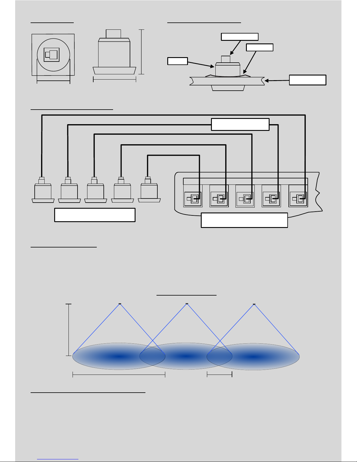
CONNECTION DIAGRAM.
MOUNTING DIAGRAM.
SENSOR INPUTS
A
B
C
D
E
SET-DLCM - Marshalling Box
Sensors
SET-PDOCH-RJ12, SET-DOL-RJ12 or SET-ALD5-RJ12
SENSOR
SPRING CLIP
RJ12 CONNECTOR
CEILING THICKNESS
Max. 15mm
47mm
50mm
38mm Diameter
DIMENSIONS
7m Diameter Coverage
2.4m
Ceiling
Height
PIR Detection Pattern
Strongest nearer centre, weakest furthest from centre
2m Overlap
RJ12 Patch Leads
PIR Detection Zones.
The PIR detection pattern consists of two ‘zones’, an inner and outer zone. The outer zone will detect large movements such as
someone walking and the inner zone will detect smaller movements such as that of an hand or arm.
PIR sensors should be mounted every 5 meters to ensure the best possible coverage, reducing ‘dead spots’ and ensuring
optimum movement detection.
Sensor Inputs and Channel Outputs.
Sensors will control the desired output channels through self-configuration on light level according to the table on page 3.
Movement detection is ‘linked’ across all channels.
 Loading...