

Setra Systems SSC-2S, SSC-4S, SSC-4H, SSC-2H Operation And Installation Instructions Manual
Introduction
The Sure-Set Current Switch (SSC) Series
of digital output switches are noninvasive devices designed to detect current
owing through a cable or wire. A cost
eective solution for monitoring on and
o status or proof of operation, these
devices are ideal for monitoring the current load on motors driving fans, pumps,
chillers, compressors and blowers. The
Model SSC Current Switch has a universal power supply. Excitation is magnetically induced from the current carrying
conductor (wire or cable) being sensed,
making these devices completely selfpowered.
Warning: Risk of Electric Shock
Disconnect power supply before making electrical connections. Contact
with components carrying hazardous
voltage can cause electrical shock and
may result in severe personal injury or
death.
Warning: Risk of Arc-Flash
Disconnect power supply before making electrical connections. Contact
with components carrying hazardous
voltage can cause electric shock and
may result in severe personal injury or
death.
Setup and Adjustments
The Sure-Set Model SSC series of switches
employ a unique method to set the operating set point of the device. The Sure-Set
Current Switch is designed to allow the
installer to select the operating setpoint
prior to opening the electrical enclosure.
Since the Sure-Set does not require calibration on a powered and operating load,
the safety hazards and Personal Protective Equipment (PPE) required for protection against Arc-Flash are not necessary!
In fact, the installer or site engineer can
pre-set all Sure-Set Current Switches used
for a particular installation prior to delivering the parts to the job site. The installer
selects the proper Sure-Set model for
the application (230 VAC or 480 VAC) and
veries the Motor HP for the system to be
monitored.
Select Operating Range
1. Verify the motor Full Load HP for the
system to be monitored.
2. Verify the motor operating voltage.
3. Verify that the proper Sure-Set model
was selected to monitor the motor
used in the system. (Sure-Set Current
Switches are available for 230 VAC
and 480 VAC motors both in standard
low and high HP ranges.)
4. Set the Sure-Set operating setpoint
to the motor Full Load HP by rotating
the range selector switch on top of
the Sure-Set to the proper motor HP
(see Fig. 2). The Sure-Set operating
setpoint is now set to properly monitor the motor operation. No calibration on a live load is necessary.
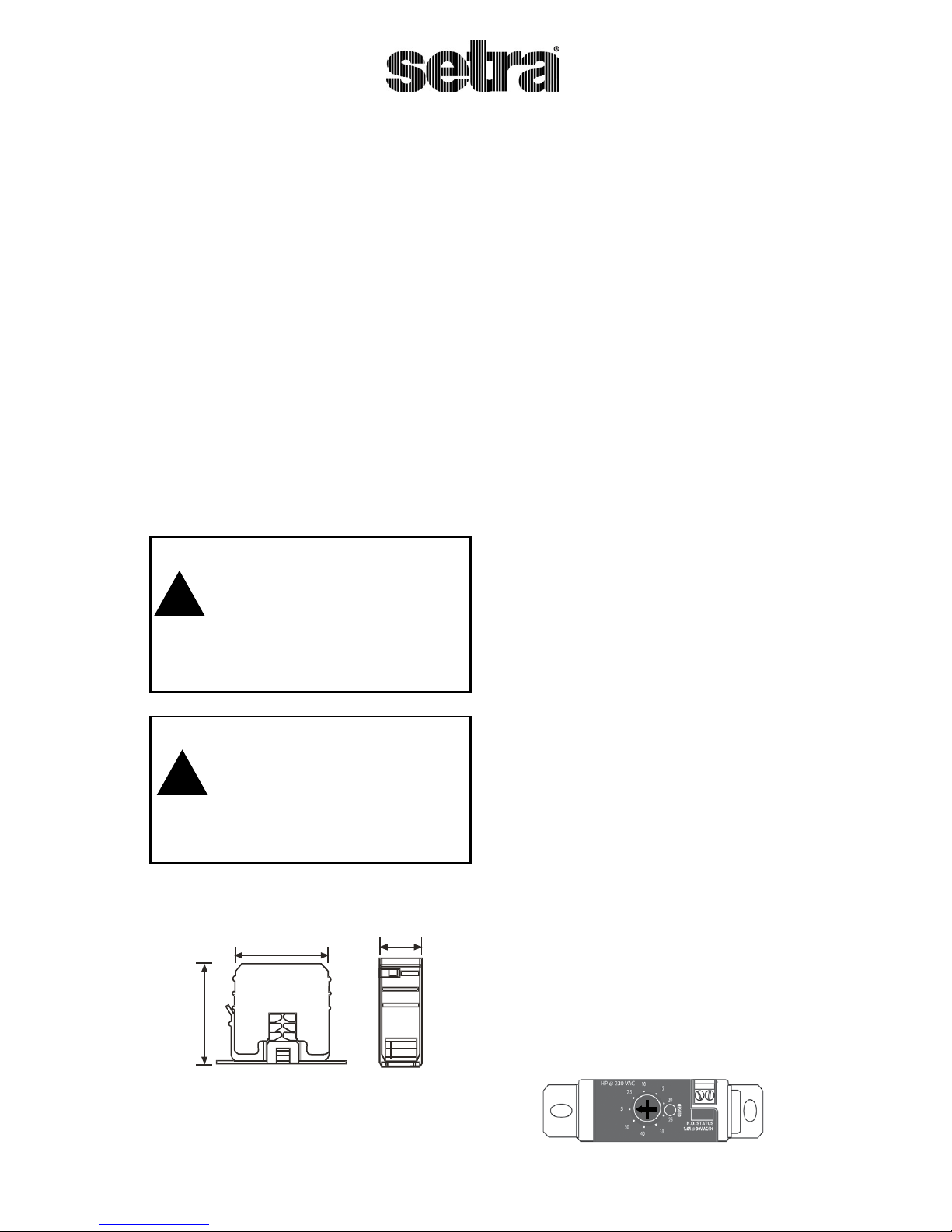
65 (2-9/16)
69 (2-23/32)
27 (1-1/16)
Fig. 1 Model SSC
Dimensions
mm(in.)
Model SSC-2S/SSC-2H/SSC-4S/SSC-4H
Operation and Installation Instructions
!
!
Fig. 2 HP Range Selector
Installation
Mounting
1. Shut o all power to the enclosure
prior to installing.
2. Remove the Sure-Set mounting
bracket from the main housing.
3. Using the two screws (included), attach the mounting bracket to the
back of the electrical enclosure. (A
piece of double side tape is included
in the hardware kit to assist holding
the mounting bracket while attaching the screws.
4. Snap the SSC into place on the
mounting bracket.
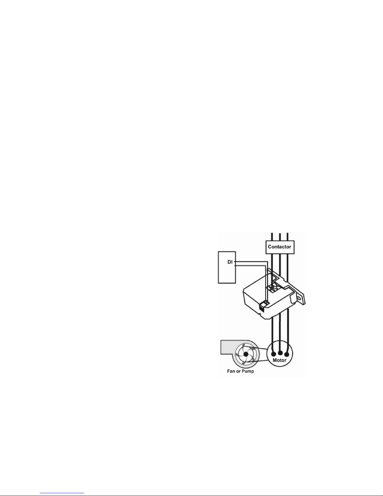
Fig. 3 Model SSC Typical Wiring
Wiring
1. Disconnect power to the conductor
cable from the power source prior to
proceeding.
2. Snap the split core around the power
conductor cable, and close the housing until the latch snaps shut.
3. Wire SSC output terminals to the
control box Digital Input (DI) terminal (30 V max. terminal voltage).
Note: the output switch contacts are solid
state, and they work just like dry contacts.
When the output switch is closed, less than
1 ohm is present; when the output switch is
open, more than 1 ohm is present.
4. Close the enclosure and reconnect
power to the power conductor cable.
(For wiring example, see Figure 3.)

RETURNING PRODUCTS
FOR REPAIR
Please contact a Setra application engineer (800-257-3872, 978-263-1400) before returning unit for repair to review
information relative to your application.
Many times only minor eld adjustments
may be necessary. When returning a product to Setra, the material should be carefully packaged and shipped to:
Setra Systems, Inc.
159 Swanson Road
Boxborough, MA 01719-1304
Attn: Repair Department
To assure prompt handling, returned
unit(s) must be accompanied by Setra’s
Return Order Form,completely lled out,
found on Setra’s website at http://www.
setra.com/tra/repairs/cal_rep.htm.
Note: Please enclose any required mating electrical connectors and wiring diagrams. Allow approximately 3 weeks after
receipt at Setra for the repair and return
of the unit. Non-warranty repairs will not
be made without customer approval and
a purchase order to cover repair charges.
WARRANTY AND LIMITATION OF LIABILITY
SETRA warrants its products to be free from
defects in materials and workmanship, subject
to the following terms and conditions: Without
charge, SETRA will repair or replace products
found to be defective in materials or workmanship within the warranty period; provided that:
a) the product has not been subjected
to abuse, neglect, accident, incorrect
wiring not our own, improper
installation or servicing, or use in
violation of instructions furnished by
SETRA;
b) the product has not been repaired or
altered by anyone except SETRA or its
authorized service agencies;
c) the serial number or date code has not
been removed, defaced, or otherwise
changed; and
d) examination discloses, in the judgment
of SETRA, the defect in materials or
workmanship developed under normal
installation, use and service;
e) SETRA is notied in advance of and
the product is returned to SETRA
transportation prepaid.
Unless otherwise specied in a manual or
warranty card, or agreed to in writing and
signed by a SETRA ocer, SETRA pressure,
current, humidity, and acceleration products
shall be warranted for one year from date
of sale. The foregoing warranty is in lieu of
all warranties, express, implied or statutory,
including but not limited to, any implied
warranty of merchantability for a particular
purpose. SETRA’s liability for breach of warranty
is limited to repair or replacement, or if the
goods cannot be repaired or replaced, to a
refund of the purchase price. SETRA’s liability
for all other breaches is limited to a refund
of the purchase price. In no instance shall
SETRA be liable for incidental or consequential
damages arising from a breach of warranty, or
from the use or installation of its products.
No representative or person is authorized
to give any warranty other than as set out
above or to assume for SETRA any other
liability in connection with the sale of its
products.

Symptom Action
SSC solid state output does not change state when
motor current is changed.
Insucient current to the load to reach the selected setpoint
threshold.
Incorrect motor HP range selected Verify that the Sure-Set range
selector switch is set to the proper motor FLA.
Incorrect Sure-Set model chosen. Check motor Full Load HP against
the Sure-Set HP ranges.
Check that the proper Sure-Set model was chosen for the motor
operating voltage.
The clamp is not fully closed. Press the Sure-Set housing to ensure
the clamp latch is fully closed. Verify that the conductor is within
the range of the conductor sizes that can be accommodated by the
Sure-Set.
Motor is turned on and switch does not close. Verify that the range selector switch is set to the proper motor FLA.
Troubleshooting
Table 1: Troubleshooting
The performance specications are nominal and conform to acceptable industry standards. For application of
conditions beyond these specications, consult your local Setra representative. Setra Systems, Inc. shall not be
liable for damages from misapplication or misuse of its products.
For all CE technical questions, contact Setra Systems, USA. EU customers may contact our EU representative
Hangstler GmbH, Uhlandstr 49, 78554 Aldingen, Germany (Tel: +49-7424-89500).
159 Swanson Road, Boxborough, MA 01719/800-257-3872;
Fax: 978-264-0292; Email: sales@setra.com/Web: www. setra.com
SS-SureSet Rev. A 3/27/2013
Technical Specications
MODEL SSC-2S SSC-4S SSC-2H SSC-4H
Motor Hp Range 1, 2, 3, 5, 7.5, 10,
15, 20, 25
2, 3, 5, 7.5, 10, 15,
20, 25, 30
5, 7.5, 10, 15, 20,
25, 30, 40, 50
15, 20, 25, 30, 40,
50, 60, 75, 100
Continuous Operating Current 135A, 600V AC
Switch Setpoint Adjustable, 9 position selector switch
Output Relay Contacts (option) Optional. Output contacts rated 10A @ 260V AC, 5A @ 30V DC
Output Relay Coil Voltage (option) Optional, 12V AC/DC or 24V AC/DC
Switch LED Indication Yes Yes Yes Yes
Relay LED Indication (option) Yes Yes Yes Ye s
Trip Point Set Value 35% below FLA @ selected Hp value
Current Switching Mode Under Current Sensing
Dimensions 2.7 x 2.56 x 1.08 in.
(69 x 65 x 27 mm)
2.7 x 2.56 x 1.08 in.
(69 x 65 x 27 mm)
2.7 x 2.56 x 1.73 in.
(69 x 65 x 44 mm)
2.7 x 2.56 x 1.73 in.
(69 x 65 x 44 mm)
Aperture Size 0.72 x 0.78 in. (18 x 20 mm)
Sensor Power Source Induced from power conductor cable
Status Output Switch normally open
Switch Load Capacity 1A @ 30V AC/DC max.
Isolation Voltage 600V AC rms.
Temperature Range 5 to 140°F (-15 to 60°C)
Frequency Range 50/60 Hz
Humidity Range 0 to 95% non-condensing
Agency Approvals/Compliance CE Compliant, RoHS Compliant, UL/c-UL Listed: 508, IND. Cont. EQ: E317719
Patents Pending
 Loading...