

Page 1
SRIM
Operating Instructions
Setra Systems, Inc.
159 Swanson Road, Boxborough, MA 01719
800.257.3872 • www.setra.com
Page 2

2
Table of Contents
1.0 Introduction .................................................................................................................... 3
1.1 Intended use .............................................................................................................. 4
2.0 Mechanical installation ................................................................................................ 4
3.0 Electrical installation ..................................................................................................... 5
3.1 Plumbing and wiring to the electrical box (rough in) .............................................. 6
4.0 Operation ...................................................................................................................... 10
5.0 Calibration and adjustment of zero output .................................................................20
6.0 Maintenance & troubleshooting .................................................................................. 20
Page 3

3
1.0 Introduction
The SRIM1 has a non backlit LCD display and alarms on pressure. It is capable of true 2 wire
4-20 mA loop powered operation. The SRIM2 is a 3 wire has a 3 color backlight, a digital input
for a door switch, 2 analog inputs for temperature and humidity and 1 relay output for remote
alarm indication. It can alarm on Pressure, temperature and humidity parameters.
Monitor room parameters
• Room pressure
• Temperature
• Humidity
• Door status (open or closed)
User interface
• Large LCD 2 line display, room pressure, temperature (optional) and humidity (optional) as
well as room status indication.
• Green (normal), yellow (warning), red (alarm) backlit display for indicating the room status
for SRIM2, monochrome for SRIM1.
• Membrane keypad for ease of conguration and menu navigation.
• Password protection for security.
Audible visual and remote alarms
• Color backlight LEDs.
• Alarm on pressure, temperature and humidity.
• Audible buzzer.
• Alarm delay, mute timeout, alarm enable/disable, buzzer enable/disable.
• SPDT relay for remote alarms, including Setra Remote Annunciator (SRAN).
Ease of installation use and calibration
• Flush mount and duct mount versions, both wipe down for decontamination.
• Rotate-able pressure ttings to eliminate crimping of pressures hoses, allows installation
flexibility.
• Snap on cover, no visible fasteners.
• Modular plug in design using sub-base. Simultaneous electrical and plumbing connections
reduce initial installation and calibration costs. Unit can be calibrated in house or sent to
calibration service without removing the wiring or plumbing.
• Push button zero and span calibration, no potentiometer adjustments.
• PG9 and conduit tting in same unit, eld selectable.
Versatile
• Field selectable outputs, 4-20 ma. 0-5 VDC and 0-VDC
• Unidirectional or bidirectional ranges, eld selectable
Page 4

4
1. 1 Intended use
The Setra SRIM Room Isolation Pressure Monitor is designed for critical low differential
pressure applications that require stringent pressure monitoring and alarming. The SRIM can
be congured to monitor positive, negative or neutral pressures in protected environments.
The SRIM is a complete system that includes a 2 line LCD display with large characters for
the pressure, temperature and humidity indication and room status. The membrane keypad
user interface enables access to setup, security, calibration, and alarm setups. Backlight
LED’s (SRIM2) provide a local visual indication of the room pressure alarm status and a local
audible alarm (with time delay feature) alert personnel to system status. Analog outputs are
available in 4-20 mA, 0-5 or 0-10 VDC in the same unit. True differential pressure is displayed
with a resolution of up to .0001” as well as the room status. Setra’s patented very low pressure
capacitance sensor is dead ended and avoids the potential for cross contamination of the room
and reference space as well as eliminating drift that results from fouling of flow based sensors,
which by nature have a flow path connecting the protected and reference spaces.
2.0 SRIM included parts
The SRIM parts list includes:
• SRIM isolation room monitor
• Electrical plugs for ½” conduit or PG9 strain relief connector.
• RPS pressure taps 0, 1 or 2 as ordered, including mounting screws.
The RPS is mounted to a single gang box. One is typically located in the isolation room and the
second is mounted in a corridor (reference pressure). The back of the RPS has a barbed tting
for plastic tubing to be connected to the SRIM.
Fig. 2-1 Parts
Fig. 2-2 RPS pressure taps
Page 5
5
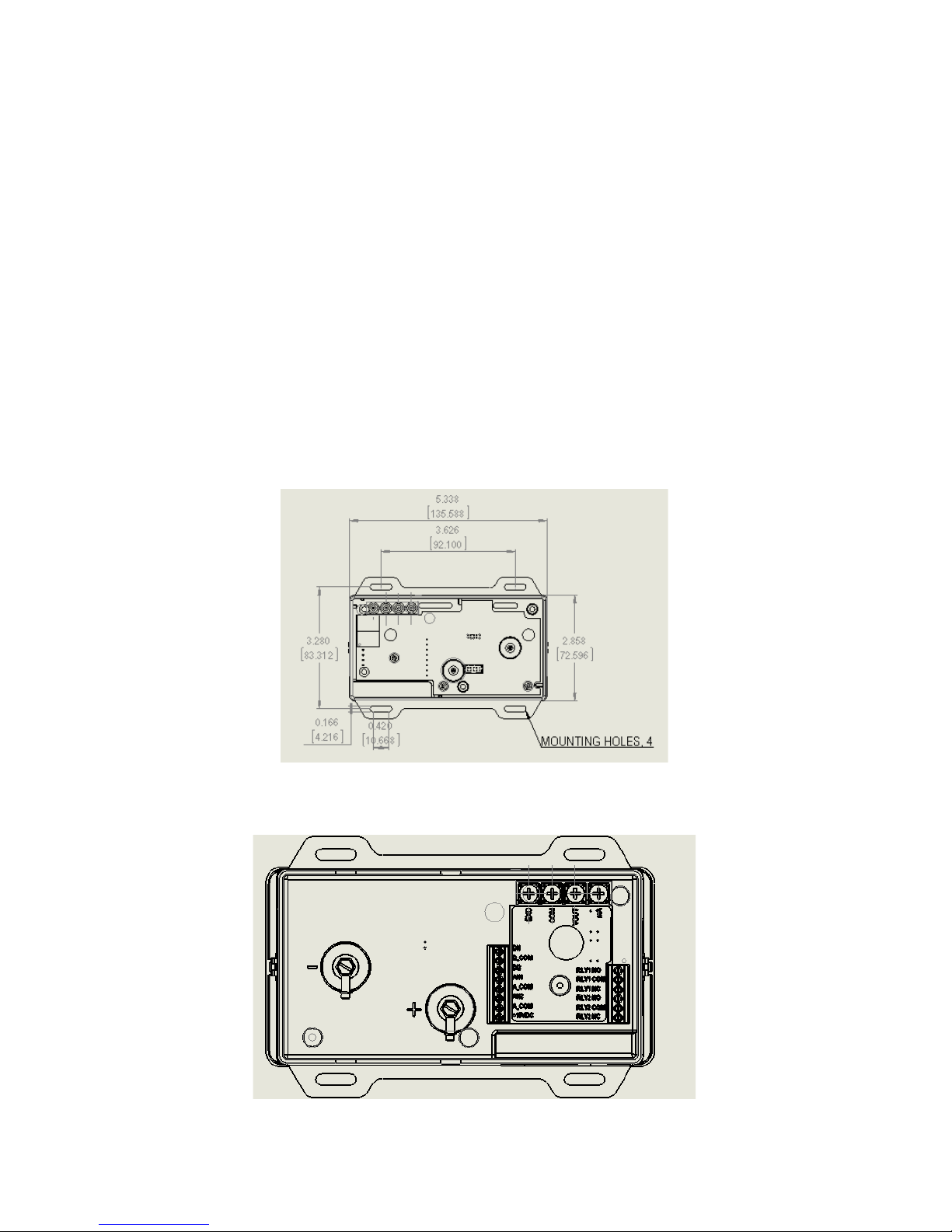
Fig. 3-1 Wall (flush) mount housing dimensions, front view, SRIM1,2
Fig. 3-2 SRIM2 wall (flush) mount housing rear view of pressure ttings
and electrical terminations.
3.0 Installation
The SRIM is available in two models suitable for wall (flush mount) and surface mounting (or
panel mounting). The front panel of the product and product rear housing are snapped together,
the two snaps are located on the left and right sides of the front panel. A 1.5mm 1/16 inch Allen
wrench or paper clip can be used to open the concealed snap fastening system.
The rear housing can be used to mount to a wall or into a 3 gang “off the shelf” electrical box.
Conduit (1/2”) or a PG9 cable connection are available for wiring to the terminals at the rear of
the unit. The rear housing acts much like a sub-base that does not have to be removed once
installed.
The front bezel contains the pressure sensor, PCBA and display. It is a complete module that
can be calibrated. The pressure and electrical connectors are disconnected simultaneously
when the front bezel is removed.
Before installing determine a good installation location. For Flush mount applications, the
corridor outside the isolation room is preferred. For Surface mount applications the unit may
be mounted on the duct work (avoid high vibration), a stable surface near the ductwork or
inside a panel.
Page 6

6
Unpack the product box. Do not remove the protective lm on the front panel until after
installation to prevent scratching of the display during the installation process. Remove parts
and place them on flat surface. Apply pressure on the side of the box to open the snap t or
use an allen wrench or paper clip as shown See Figure 1-2. First one side then the other, then
pull the bezel forward to remove it from the housing.
Fig. 3-3 Removing bezel from the base
Fig. 3-4 Rough plumbing and wiring to rough-in box, flush mount unit
3.1 Plumbing and wiring to the electrical box (rough in)
Flush mounting:
Use a 3 gang electrical box RACO 697 or equivalent or mount directly into the wall. If mounting
directly into the wall create an opening approximately 2.8” (71 mm) by 5.4” (134 mm). If using
the 3 gang box use #6 machine screws to mount the ears of the SRIM rear housing to the
electrical box. If mounting directly into the wall without an electrical box, use drywall screws
to mount the 4 ears of the SRIM box to the wall.
Page 7
7
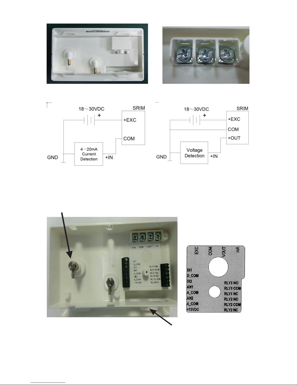
Fig. 3-5 Wiring diagram SRIM1 and back of unit
Fig. 3-5 Wiring diagram SRIM1 and back of unit
Pull wires through the openings in
the bottom of the base. 1/2” conduit
or PG9 tting openings are provided.
Rotating pressure ttings, can point
up or down, SRIM2 only.
- Pressure
+(High)
Pressure
+EXC COM +OUT
Page 8

8
Terminal Function
EXC +24 VDC supply
COM Power supply COM and analog out COM
VOUT Analog output + (VDC mode)
mA Analog output (mA output mode)
D1 Door status, wire to one side of NO contact
D_COM Door status, wire to other side of NO contact
D12 Not used
AN1 + output of temperature sensor (if used)
A_COM
Common output of temperature and humidity sensors
(if used)
AN2 + output of humidity sensor (if used)
COM 15V power common (return)
+15VDC Power for remote annunciator (if used)
RLY1 NO Relay 1 normally open contact
RLY1
COM
Relay 1 common contact
RLY1 NC Relay 1 normally closed contact
RLY1 NO Not used
RLY1
COM
Not used
RLY1 NC Not used
Table 1 wiring SRIM2
Page 9
9
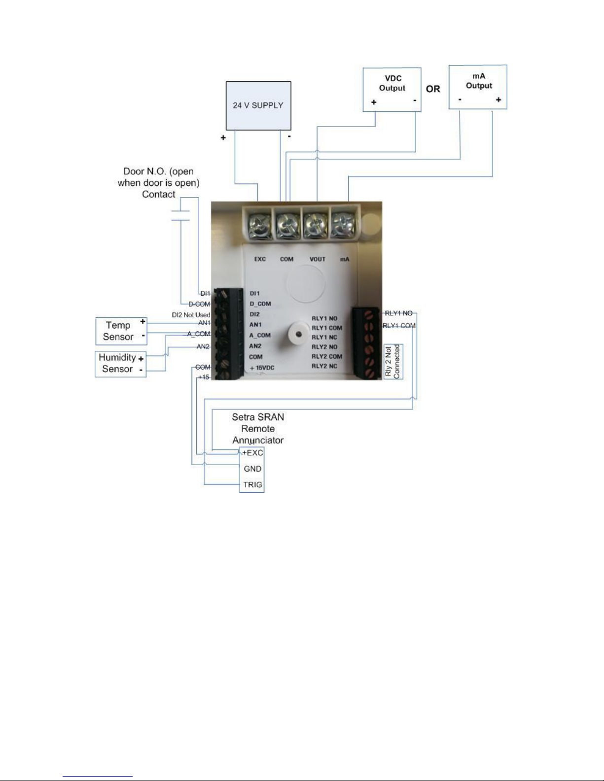
Fig. 3-7 Wiring, SRIM2
Note: Relay 1 (RLY1) is a SPDT relay that can be used to signal a remote unit of an alarm
condition. The relay contacts are rated for 3 A, 120 VAC.
Page 10

10
Fig. 3-8 Installed plugs on unused openings in the base.
Connect the pressure tubes to the high and low pressure ports. Wire to the electrical terminals
on the back of the housing. If desired, place electrical plugs on the unused holes in the base.
Complete the installation by installing the bezel onto the base by aligning the two and pushing
the bezel into the base until the bezel snaps to the base on the 2 sides. Be sure to carefully
align the 2 parts and push straight in. There are alignment features on the front bezel and rear
housing.
4.0 Menu navigation and conguration
The LCD display is standard on all SRIM products, the display provides valuable feedback during
conguration and for user feedback in the normal and alarm modes.
The SRIM1 has a non backlit LCD display and alarms on pressure. The SRIM2 has a 3 color
backlight, a digital input for a door switch, 2 analog inputs for temperature and humidity and 1
relay output for remote alarm indication. It can alarm on Pressure, temperature and humidity
parameters.
Page 11

11
Apply 24 VDC power.
The display goes through the initialization sequence, the LCD screens will the displayed in the
following order.
• Software version information.
• Product pressure range, in “WC or Pascal.
• Analog output mode, 4-20, 0-5 or 0-10 VDC.
Unit in the normal state, line 1 is the indicated differential pressure and units. Line 2 indicates
the temperature and humidity reading, if enabled . The green backlight indicates that the room
pressure, the temperature and humidity is within the allowable alarm limits. Note that the
alarm will occur if any of the 3 monitored parameters are outside of their respective limits.
Unit in the alarm state. Red backlight, arrow indicating which parameter and if it above or
below alarm limits and audible buzzer if enabled.
Page 12

12
Menu operation
Menu key – Provides access to the menu structure
Down arrow key – Allows selection of numerical parameters. Pushing the down
arrow cause the digits to move upwards in 1 digit count and will wrap around. The
cursor below the indicated item in the current menu item indicates that this is the
digit that is being changed. If you don’t need to make a change to that position press
the enter key to move to the next position to the right.
Enter key – Use this key to move left to right in a current menu screen, also used
to save the current menu item selected settings, or the conrm current menu
operation; press the Enter key to save the current settings, the display shows the
current setting value and flashes twice, and to prompt the user that the currently set
value has been saved.
Return/Silence button – This button provides a quick way to return to the home
screen from anywhere within the menu structure. It has the secondary purpose of
temporarily silencing the audible alarm. If the mute timeout setting is reached the
audible will again sound.
Menu items, in the order that they appear in the menu. These are placed in order of the
anticipated most used functions near the top of the menu tree. It is suggested that in the
initial conguration that the user progress through each section in order.
ALARM HIGH LIMIT
Sets the high pressure alarm limit, the high pressure limit
must be greater than the low pressure limit
ALARM LOW LIMIT
Sets the low pressure alarm limit
ALARM DELAY
Sets the delay (sec) between the time that the alarm high
or low limits are exceeded and when the alarm is indicated
Page 13
13
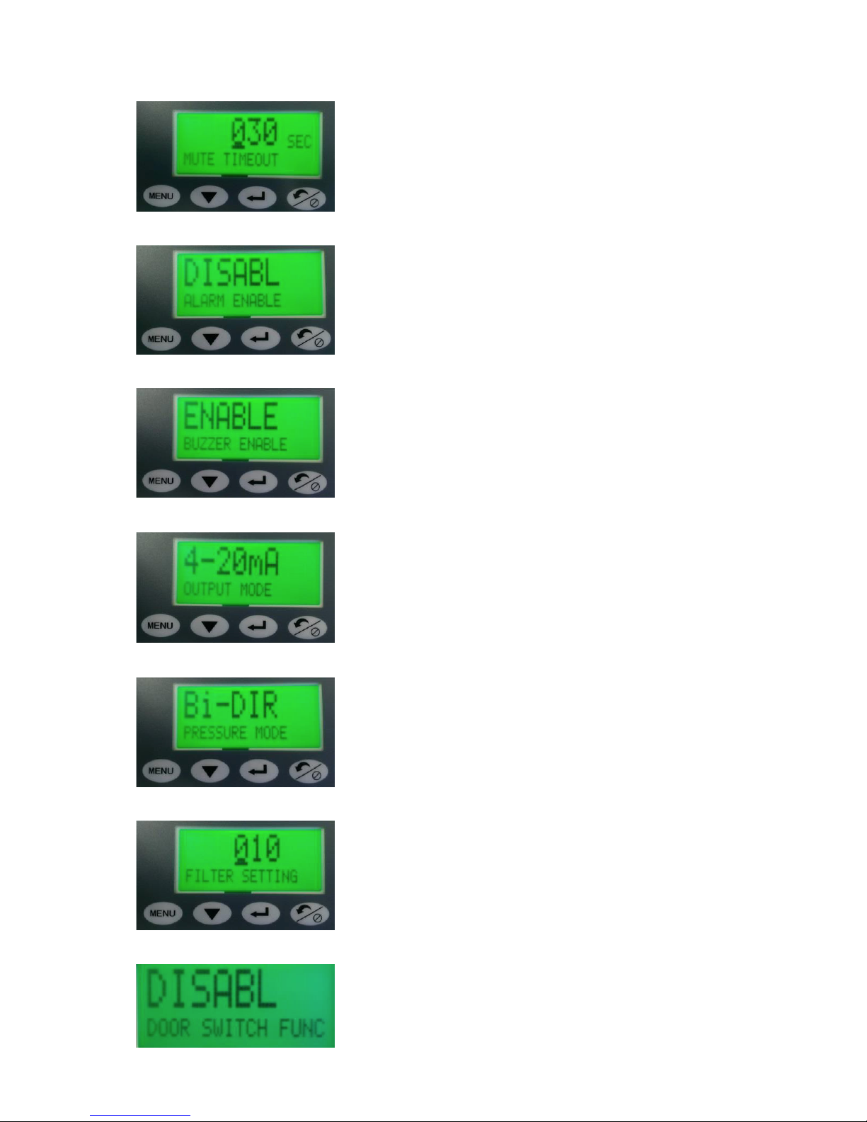
MUTE TIMEOUT
Sets the time delay (sec) between when the buzzer mute
button is pressed and when it will re-sound if the pressure
is still out of range
BUZZER ENABLE
Enables the local audible buzzer. The xed volume is
approximately 85 dBA as measured at 4-inch distance
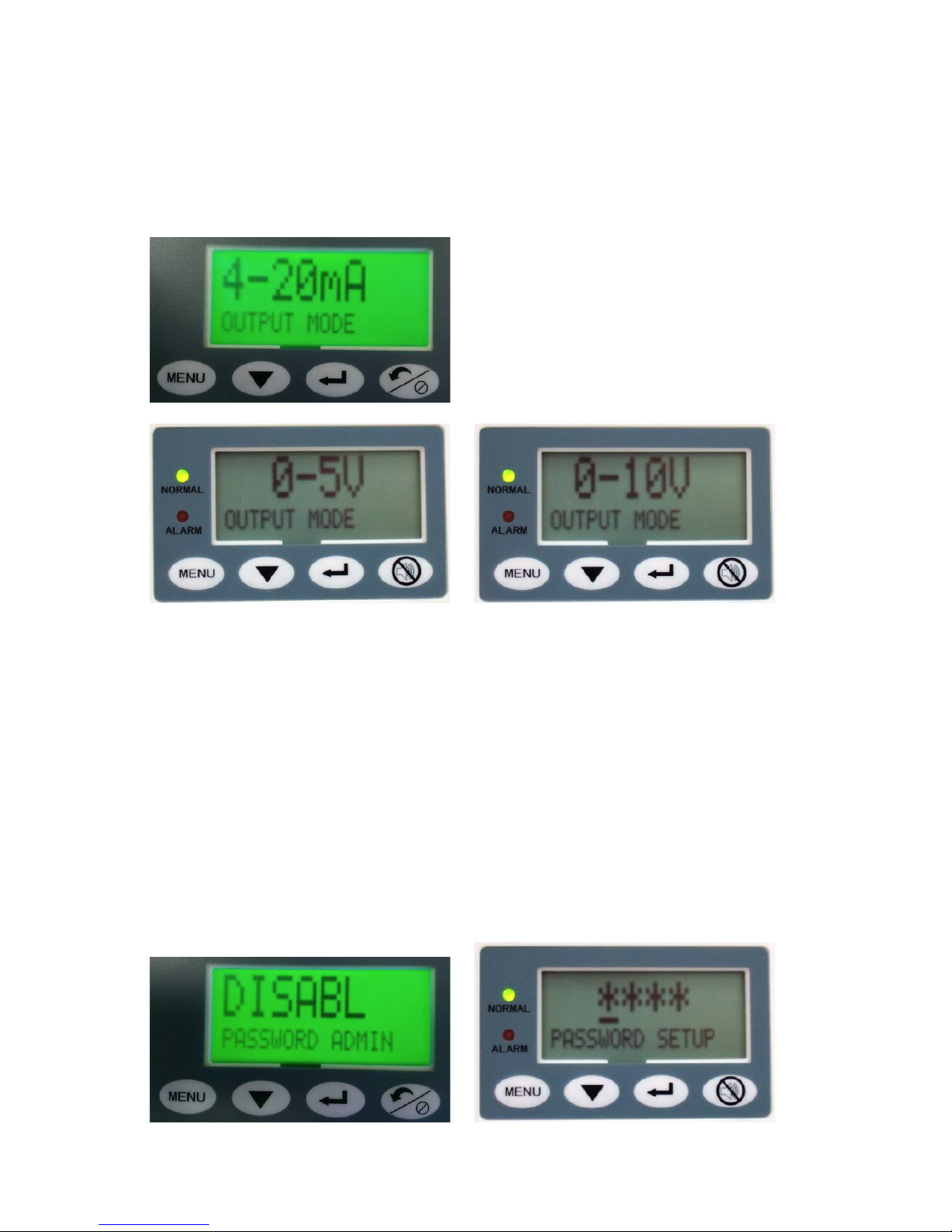
OUTPUT MODE
Sets the analog output mode, 4-20 ma, 0-5 VDC or 0-10
VDC
PRESSURE MODE
Sets the unit into unidirectional or bi-directional pressure
modes, ex: +/-0.25” or 0-0.25”WC
DOOR SWITCHING
Only Available on SRIM2. Door switch enable/disable.
Enable if used with a door switch to detect if door is open.
FILTER SETTING
(1-99), default is 10. Sets up a data averaging lter, the
lowest numbers provide the fastest output response but
highest analog output noise. In an extremely pressure
noisy environment use higher numbers until the pressure
display flickering is reduced.
ALARM ENABLE
Enables the audible and visual alarms indicators
Page 14

14
PASSWORD ADMIN
Enables or disables the 4 digit numeric password, use
backdoor password 0159, if the password is lost
ZERO CALIBRATION
“Tares” out any 0 pressure error. This must be done with 0
pressure applied.
SPAN CALIBRATION
“Tares” out any Span pressure error. This must be done
with the +Full Range (FR) pressure applied. For ex: if the
pressure range is +/-0.1” WC, apply 0.1” WC.
RESUME CAL VALUE
Restores factory calibration settings in case a calibration
may have been performed incorrectly
Page 15

15
The Temperature and Humidity functions and alarming are only available on the SRIM2.
TEMPERATURE FUNC
Temperature Function, pressing the enter key will drop
down into the setup of the external sensor for AN1 (Analog
input 1). Press menu button to move between items in this
menu.
TEMP UNIT
Pressing the down arrow toggles between Degrees C or F.
Press Enter key to select F/C
T_Min Vin
Input the analog output of the temperature sensor
corresponding lowest temperature to be measured T_Min
T. Ex: 0 V = 50 F.
T_Min T
Input the minimum temperature that corresponds to the
min. analog output T_Min Vin
T_Max T
Input the maximum temperature that corresponds to the
max. analog output T_Max Vin.
T_Max Vin
Input the analog output of the temperature sensor
corresponding lowest temperature to be measured T_Max
T. Ex: 0 V = 50 F.
TEMP ENABLE
Pressing the down arrow toggles between enable and
disable. Press enter key to select enable/disable
Page 16

16
T_ALARM L LIMIT
Set the low temperature alarm limit in Degrees C or
Degrees F
T_ALARM ENABLE
Enable or disable the Temperature alarms by using the
down arrow to toggle between selections, Press Return
key to accept
HUMIDITY FUNC
Humidity function, pressing the enter key will drop down
into the setup of the external sensor for AN2 (Analog input
2).
HUMIDITY ENABLE
Pressing the down arrow toggles between enable and
disable.
H_Min H
Input the minimum humidity that corresponds to the min.
analog
H_Min Vin
Input the analog output of the humidity sensor
corresponding lowest humidity to be measured H_Min T.
Ex: 0 V = 0%RH
T_ALARM H LIMIT
Set the high temperature alarm limit in Degrees C or
Degrees F
Page 17

17
H_Max Vin
Input the analog output of the humidity sensor
corresponding
H_ALARM ENABLE
Enable or disable the Humidity alarms by using the down
arrow to toggle between selections, Press Return key to
accept selection
RETURN
Returns from the conguration mode to the normal
operating mode
H_Max H
Input the maximum humidity that corresponds to the max.
analog
Page 18
18
Example 1: Output mode setting
To enter the menu, press the Menu key. Continue pressing until the display indicates output
mode. 4-20 mA is the default output mode, if you want to change to 0-5 or 0-10 press the
down arrow and press the return key to select. The display will blink 2X to conrm the setting
change.
Example 2: Setting the password (4 digit numerical) protection
Press the down key to select the menu item PASSWORD ADMIN, the system will prompt to
input the password, when the input is complete press the Enter key to save the password
and complete the setup. When password protection is enabled, you must enter the correct
password before you can enter the menu the view or change parameters.
Save the password in a safe location. If you forget the password, use the backdoor password
of 0159 and reset the password if desired.
Continue to press the menu key to progress all the way through the menu until you reach the
RETURN screen. Press the Enter key to exit out of the menu and return to home screen.
Page 19

19
Example 3: Calibration
Remove the pressure ports or shut of fans to the room and open the door so that zero
differential pressure is applied to the monitor.
Select menu items ZERO CALIBRATION, the display shows the current pressure value, press
the Enter key. If the reading is within allowed limits the unit will respond with the message that
calibration was successful.
Full scale calibration:
Note: The full range adjustment should be completed after zero adjustment.
Span adjustment should only be performed if a very accurate and stable Full Range pressure
can be applied, such as with a Setra MicroCal.
Apply full range pressure to the high and low pressure ports.
Select menu items SPAN CALIBRATION, the display will show the current pressure value,
press the Enter key, if the applied pressure is within allowed limits then the unit respond that
span calibration has been successful .
Page 20

5.0 Returning products for repair
Please contact a Setra application engineer (800-257-3872, 978-263-1400) before returning unit for repair to review information
relative to your application. Many times only minor eld adjustments may be necessary. When returning a product to Setra,
the material should be carefully packaged and shipped prepaid to:
Setra Systems, Inc.
159 Swanson Road
Boxborough, MA 01719-1304
Attn: Repair Department
To ensure prompt handling, please supply the following information and include it inside the package or returned material:
• Name and phone number of person to contact.
• Shipping and billing instructions.
• Full description of the malfunctions.
• Identify any hazardous material used with the product.
NOTES:
Please remove any pressure ttings and plumbing that you have installed and enclose any required mating electrical connectors
and wiring diagrams.
Allow approximately 3 weeks after receipt at Setra for the repair and return of the unit. Non-warranty repairs will not be made
without customer approval and a purchase order to cover repair chargers.
Calibration Services
Setra maintains a complete calibrations facility that is traceable to the National Institute of Standards and Technology
(NIST). If you would like to recalibrate or recertify your Setra pressure transducers or transmitters, please call our Repair
Department at 800-257-3872 (978-263-1400) for scheduling.
6.0 Limited warranty & limitation of repair
SETRA warrants its products to be free from defects in materials and workmanship, subject to the following terms and
conditions: Without charge, SETRA will repair or replace products found to be defective in materials or workmanship within
the warranty period; provided that:
a) the product has not been subjected to abuse, neglect, accident, incorrect wiring not our own, improper installation
or servicing , or use in violation of instructions furnished by SETRA;
b) the product has not been repaired or altered by anyone except SETRA or its authorized service agencies;
c) the serial number or date code has not been removed, defaced, or otherwise changed; and
d) examination discloses, in the judgment of SETRA, the defect in materials or workmanship developed under normal
installation, use and service;
e) SETRA is notied in advance of and the product is returned to SETRA transportation prepaid.
Unless otherwise specied in a manual or warranty card, or agreed to in a writing signed by a SETRA ofcer, SETRA pressure
and acceleration products shall be warranted for one year from date of sale.
The foregoing warranty is in lieu of all warranties, express, implied or statutory, including but not limited to, any implied warranty
of merchantability for a particular purpose.
SETRA’s liability for breach of warranty is limited to repair or replacement, or if the goods cannot be repaired or replaced, to
a refund of the purchase price.
SETRA’s liability for all other breaches is limited to a refund of the purchase price. In no instance shall SETRA be liable for
incidental or consequential damages arising from a breach of warranty, or from the use or installation of its products.
No representative or person is authorized to give any warranty other than as set out above or to assume for SETRA any other
liability in connection with the sale of its products.
For all CE technical questions, contact Setra Systems, USA. EU customers may contact our EU representative Hengstler GmbH,
Uhlandstr 49, 78554 Aldingen, Germany (Tel: +49-7424-890; Fax: +49-7424-89500).
Setra Systems, Inc.
159 Swanson Road, Boxborough, MA 01719
800.257.3872 • www.setra.com
SS-SRIM-EN. E 2/2019
 Loading...