

Setra Systems SRH300 Operating Instructions Manual

Model SRH300
Operating Instructions
Setra Systems, Inc.
159 Swanson Road, Boxborough, MA 01719
800.257.3872 • www.setra.com

Contents
1.0 General information ..........................................................................................................................3
2.0 Caution .................................................................................................................................................3
3.0 Connection diagrams.........................................................................................................................3
4.0 LED indication......................................................................................................................................4
5.0 Display ..................................................................................................................................................5
6.0 Scope of supply...................................................................................................................................5
7.0 BACnet or Modbus setup .................................................................................................................6
7.1 BACnet address using address switch ................................................................................6
7.2 BACnet address using software ............................................................................................7
7.3 Modbus address using software ..........................................................................................9
7.4 Modbus address using address switch.............................................................................11
7.5 Modbus setup .........................................................................................................................12
8.0 Technical data ...................................................................................................................................13
9.0 Setup and adjustment ....................................................................................................................14
10.0 Maintenance .................................................................................................................................15
10.1 Humidity calibration and adjustment ..............................................................................15
10.2 Temperature calibration and adjustment .......................................................................15
10.3 When employed in dusty, polluted environment............................................................15
11.0 Accessories ....................................................................................................................................16
12.0 Returning products for repair .......................................................................................................17
12.1 Calibrated services ..............................................................................................................17
13.0 Limited warranty and limited repair ..........................................................................................18
3
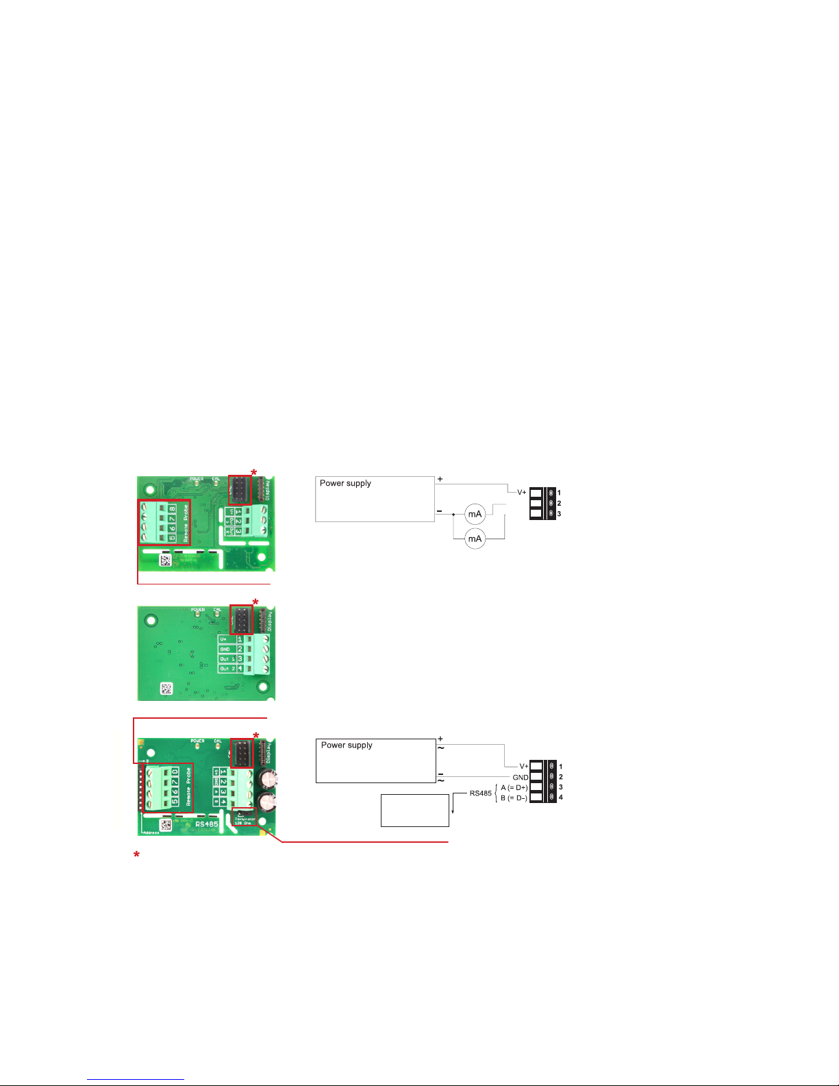
3.0 Connection diagrams
1.0 General Information
The SRH300 transmitter, available for wall or duct mounting as well as with remote probe,
is designed for highly accurate measurement of humidity and temperature in demanding
climate control applications.
For use in special applications do not hesitate to contact Setra or a local distributor.
2.0 Caution
• For accurate measurement, it is essential that the temperature of the sensing probe and the
sensing head is same as the temperature of the air to measure. Avoid mounting the SRH300
transmitter in a way which creates temperature gradients along the probe.
• The transmitter and the sensing head should not be exposed to extreme mechanical stress.
• The transmitter must be operated with the lter cap on at all times. DO NOT touch the
sensors inside the sensing head.
SRH300 - Analog milliamps
20...30 V DC RL<500 Ohm
11...30 V DC R
L
<50 Ohm
Output: 4-20 mA
OUT1
OUT2
Output: 0-5 V
0-10 V
0-20 mA
15...35 V DC
24 V AC ±20 %
V
mA
V
mA
OUT1
OUT2
SRH300 - Analog volts
Only for remote probe!
Important: The SRH300 (4-20 mA) with display operates correctly
only if both outputs are connected. If no outputs are connected,
then a jumper wire between the two outputs is required (in addition
two negative power wire).
20...30 V DC RL<500 Ohm
11...30 V DC R
L
<50 Ohm
Output: 4-20 mA
Output:
Modbus RTU or
BACnet MS/TP
15...35 V DC
24 V AC ±20 %
OUT1
OUT2
Output: 0-5 V
0-10 V
0-20 mA
15...35 V DC
24 V AC ±20 %
V
mA
V
mA
OUT1
OUT2
SRH300 - Digital
Only for remote probe!
Bus termination resistor 120 Ω (jumper)
configuration connector
4
4.0 LED indication (remove faceplate to view)
Green LED Blue LED
On Everything okay
Setra Product Conguration Adapter
(SETRAPCA1) is powered, no
communication in progress
Flashing
Main board does not recognize the
measurement electronics inside the
sensing probe
PCA powered, communication in
progress
Off No power supply or main board failure PCA not connected to the SRH300
NOTE:
This is an intelligent probe with digital output and as such it is interchangeable. In case the
probe or its cable gets destroyed or if a longer cable is needed, please order a replacement
probe according to SRH300 accessory sheet. The replacement probe shall be installed as
described above.
IMPORTANT:
Make sure that the cable ttings are closed tightly for both SRP300 probe cable and for the
power supply and outputs cable. This is necessary for assuring the protection class (IP class)
of the enclosure according to SRH300 specication, as well as for stress relief at the screw
terminals on the SRH300 board.
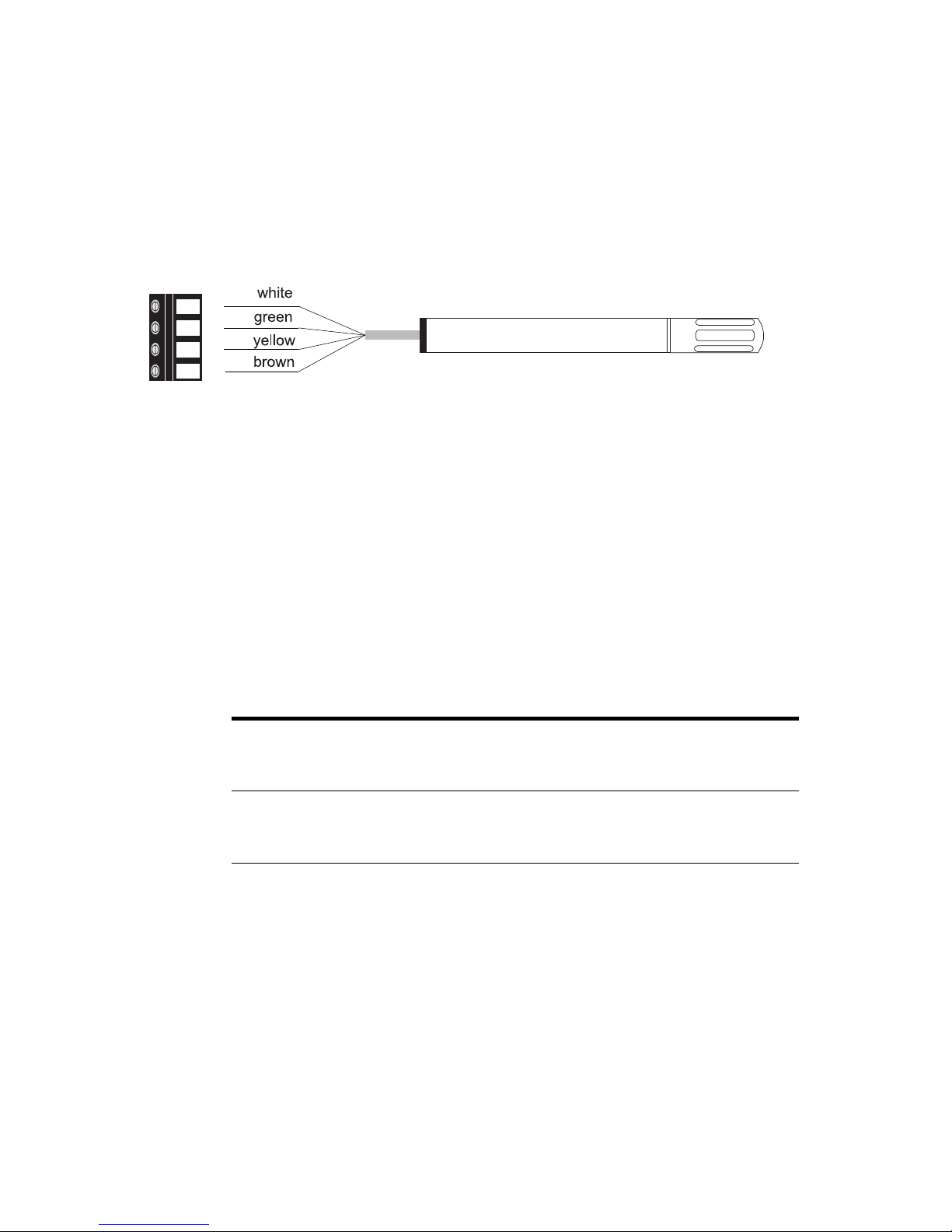
SRP300
The SRH300 with remote probe are supplied as separate items. The probe is connected as
shown below.
• First, install rst the cable tting (included in SRH300 scope of supply) onto the SRH300
enclosure.
• Before connecting the probe, disconnect the SRH300 power supply.
• Insert the probe cable through the cable tting and connect it to the screw terminals
according to the connection diagram below.
5
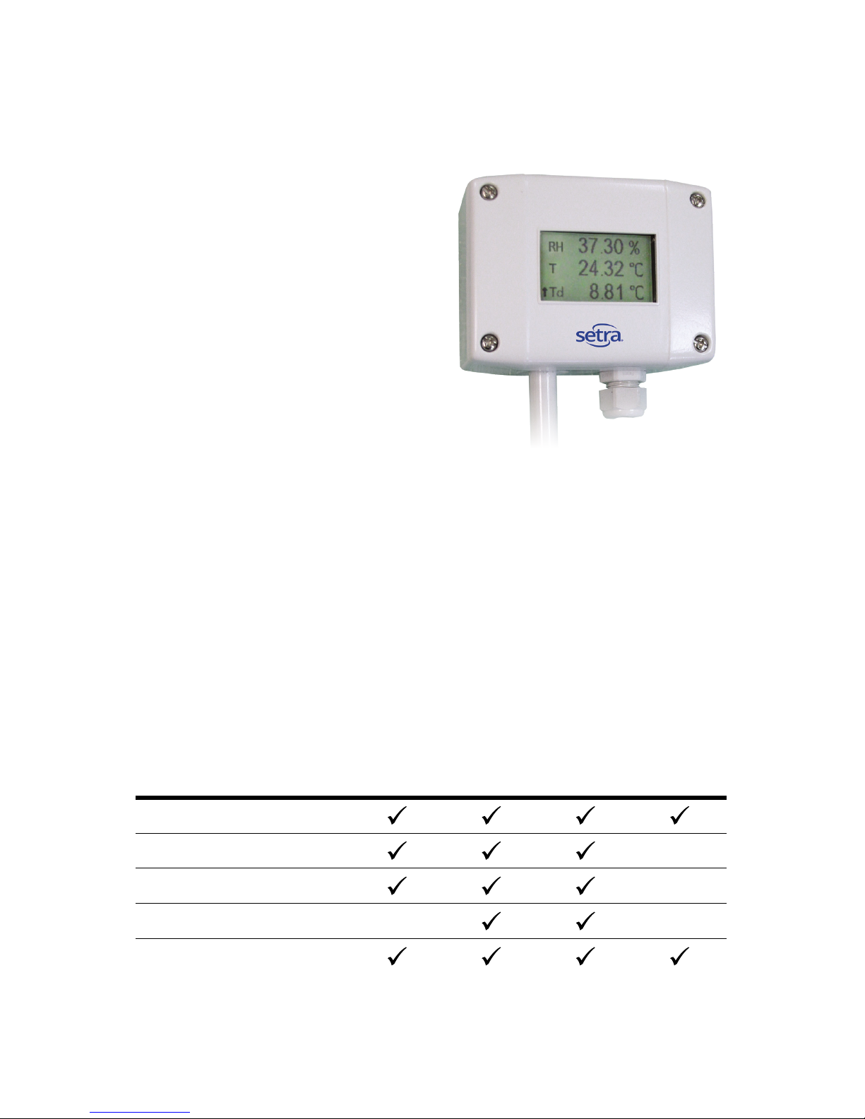
5.0 Display
Factory Setup:
The display shows the two parameters selected
for output 1 and output 2, RH and T.
User Setup:
The user can change the display layout to 1, 2 or
3 lines and select the parameters to be displayed
by using Setra Product Conguration Software
(free download from www.setra.com) and the
optional SETRAPCA1 Product Configuration
Adapter (not included in the scope of supply).
IMPORTANT:
The SRH300 (4 to 20 mA) with display operates correctly only if both outputs (RH and T) are
connected. If you choose not to send output signals to a remote monitoring location, the two
output connections must be joined using a jumper wire (not included). 4-20 mA units with no
display do not require a jumper and do not require both outputs to be connected. Voltage output
units also do not require both outputs to be connected.
Model
SRH300
Wall mount
(Type A)
SRH300
Duct mount
(Type B)
SRH300
Remote
version
(Type C)
Remote
probe* for
Type C
SRH300 according to ordering guide
Cable gland
Mounting materials
Mounting flange
Calibration & inspection certicate
(EN10204-3.1)
6.0 Scope of supply
6
7.0 BACnet or Modbus setup
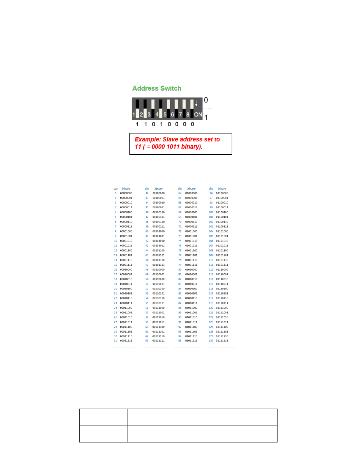
7.1 Setting BACnet address using the address switch
Remove the units faceplate. You will see an address switch (pictured below). If you wish to set
the address of the unit using this switch, you must rst identify and make note of an available
address found on your network.
SRH200 Default=2 Permitted=0...127 (BACnet)
SRH300 Default=1 Permitted=0...127 (BACnet)
Before connecting the device to your network, set the address you wish to have on the switch
following the above format and table below.
Note: You will see from the table there are 8 positions. For this device, the 8th position (or 8th
bit) is ignored.
For example: ID127=0111111
BACnet PICS for this unit are available for download at www.setra.com. This unit’s ID as well
as many other properties are also read/writable from your BACnet console.
 Loading...