

Setra Systems MS1, MS2, MS3, MS4 Installation Manual
Installation Guide
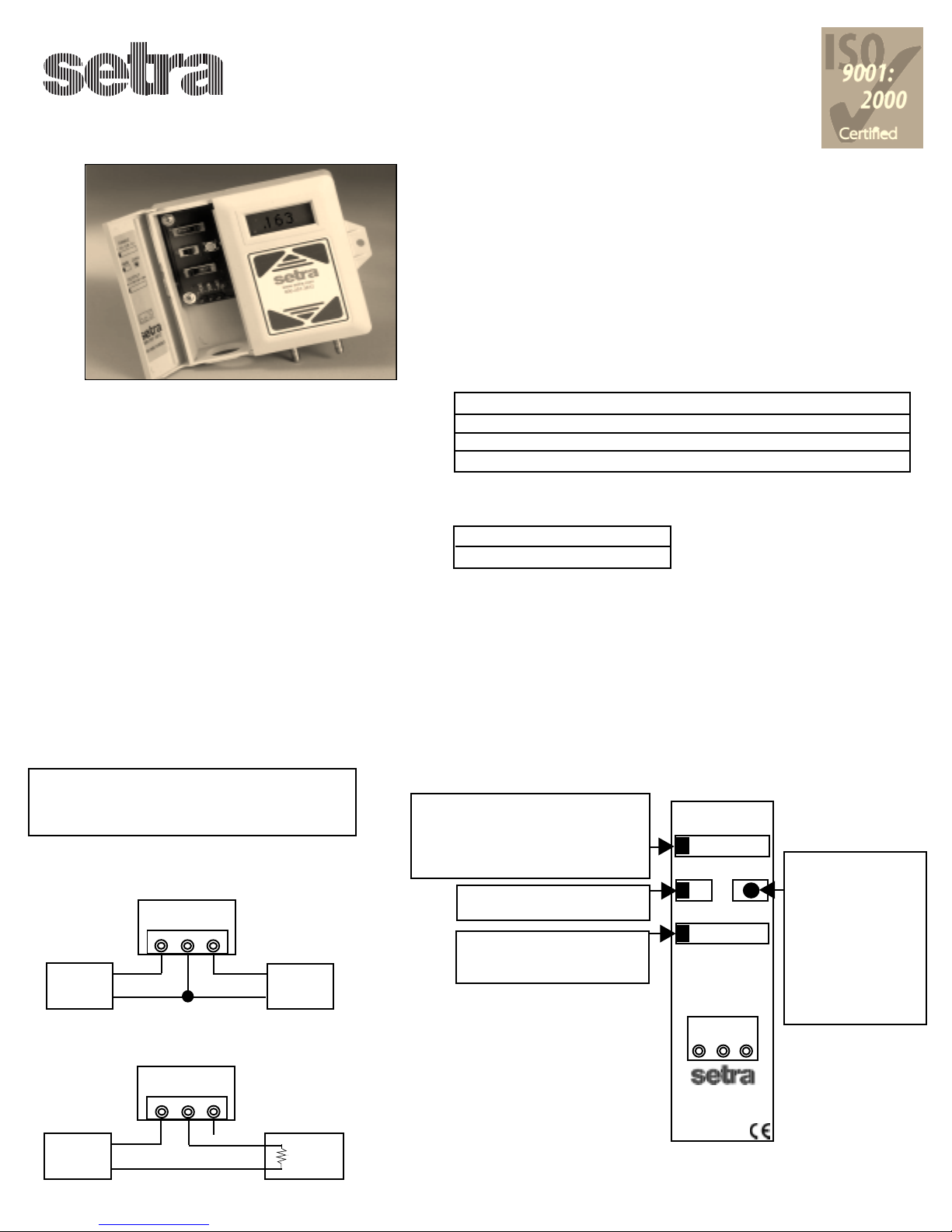
“Multi-Sense” Model 260 Series
Multi-Range Differential Pressure Transducer
MECHANICAL INSTALLATION
Mounting Position
Mount and calibrate in vertical position for quick and easy installation
on ducts, w alls or c eilings and in c ontrol r ooms .
GENERAL INFORMATION
Every Model 260 has been calibrated and tested before shipment to guarantee
performance for all pressure ranges.
The Model 260 is available in four versions, which have field selectable range
capability via a slide switch. See four versions below:
MULTI-SENSE RANGE SPECIFICATIONS
Ranges
Version Unidirectional Bidirectional
Model MS1 0.1”, 0.25”, 0.5” and 1.0” W.C. FS +/- 0.1”, 0.25”, 0.5” and 1.0” W.C. FS
Model MS2 1.0”, 2.5”, 5.0” and 10” W.C. FS +/- 1.0”, 2.5”, 5.0” and 10” W.C. FS
Model MS3 25, 50, 100 and 250 Pa FS +/- 25, 50, 100 and 250 Pa FS
Model MS4 .25, .50, 1.00 and 2.5 kPa +/- .25, .50, 1.00 and 2.5 kPa
Media Compatibility
Model 260 transducers are designed to be used with air or
nonconducting gases.
Use with liquids or corrosive gases will damage the unit.
Environment
The operating temperature limits of the 260 are as follows:
Operating Temperature 32°F to 122°F (0°C to 50°C)
Compensated Temperature Range 32°F to 122°F (0°C to 50°C)
SIMPLE 5-STEP SETUP INSTRUCTIONS STEP 1
ELECTRICAL CONNECTIONS
Removable Terminal Block for Easy Wiring
STEP 1: Wire and Power Up Unit - Follow diagrams
below for 2-wire and 3-wire configurations.
After completing wiring requirements - Apply
power to the Model 260.
Multi-Sense Voltage
3-Wire, 1-5, 0-5, 0-10 VDC Configuration
24V AC/DC
Nominal
Excitation
Power
Supply
13 - 30V
Model 260
EXC COM OUT
+ +
+
-
+
-
Voltage
Monitor
Multi-Sense Current
2-Wire, 4-20 mA Configuration
The Model 260 is available in four field selectable output configurations. See four
versions below:
2-Wire 4-20 mA (Current)
3-Wire 1-5, 0-5, or 0-10 VDC (Voltage)
SIMPLE 5-STEP SETUP INSTRUCTIONS - STEPS 2 - 5
Power On - LCD Display
Display momentarily toggles thru all existing setup parameters on initial power
up. Pressure is normally indicated on display. Units are either in inches of water
column (WC) MS1 & MS2, or Pascal (Pa) MS3 & MS4.
*STEP 2: Select Pressure Range: Set
appropriate full scale range using
the Slide Switch Multiplier.
LCD will momentarily indicate
selected range.
STEP 3: Select Unidirectional
or Bi-directional mode.
STEP 4: Select Current (mA)
or Voltage 1-5, 0-5, or
0-10 VDC output range.
*Step 2 will follow same
instructions for other inches of
water column and pascal
ranges.
RANGE:
1 0.5 0.25 0.1
UNI/BI ZERO
mA/1-5V/5V /10V
+
+-
EXC COM OUT
STEP 5: Push Button
Zero - While at
zero pressure
Press and hold
the Zero Push
Button for 1
second to
automatically
reset output to
zero.
+
-
Model C260
EXC COM OUT
-
+
X
+
Current
Monitor
-
24V (DC Only)
Nominal
Excitation
Power
Supply
13 - 30V
Typical 250 Ohm
Sense Resistor
for 1-5V Output
Measurement
2601MS1
S/N:
Date Code

PERFORMANCE SPECIFICATIONS
Accuracy RSS* (at constant temperature.) ±1% FS
*RSS of Non-Linearity, Non-Repeatability and Hysteresis.
Thermal Effects
Compensated Range °F(°C) +32 to +122°F (0 to 50)
Zero/Span Shift %FS/°F(°C) 0.02 (0.036)
Maximum Line Pressure 10 PSI
Warm-up Shift ±0.2% FS total
Position Effects
(Unit is factory calibrated at 0g effect in the vertical position)
Zero Offset (%FS/G) 0.2%
RETURNING PRODUCTS FOR REPAIR
Please contact a Setra application engineer (800-257-3872, 978-263-1400) before returning unit for repair to review information relative to your
application. Many times only minor field adjustments may be necessary. When returning a product to Setra, the material should be carefully packaged
and shipped prepaid to:
Setra Systems, Inc.
159 Swanson Road
Boxborough, MA
01719-1304
Attn: Repair Department
To download return form, please visit www.setra.com/tra/repairs/cal_rep
To assure prompt handling, please supply the following information and include it inside the package or returned material:
1. Name and phone number of person to contact.
2. Shipping and billing instructions.
3. Full description of the malfunction.
4. Identify any hazardous material used with product.
Allow approximately 3 weeks after receipt at Setra for the repair and return of the unit.
Non-warranty repairs will not be made without customer approval and a purchase order to cover repair charges.
Calibration Services
Setra maintains a complete calibration facility that is traceable to the National Institute of Standards & Technology (NIST). If you would like to recalibrate or
recertify your Setra pressure transducers or transmitters, please call our Repair Department at 800-257-3872 (978-263-1400) for scheduling.
WARRANTY AND LIMITATION OF LIABILITY
SETRA warrants its Model 260 Transducer products to the original consumer purchaser against defects for a period of one year from the date of sale by SETRA,
as shown in its shipping documents.
Without charge, SETRA will repair or replace products found to have manufacturing defects within the warranty period.
The serial number or date code must not have been removed, defaced or otherwise changed. SETRA must be notified in advance of any returns; any products returned to SETRA must be transportation prepaid.
The foregoing warranty is in lieu of all warranties, express, implied or statutory, including but not limited to, any implied warranty of merchantability for a particular purpose.
SETRA’s liability for breach of warranty is limited to repair or replacement, or if the goods cannot be repaired or replaced, to a refund of the purchase price. SETRA’s liability for all other breaches is
limited to a refund of the purchase price. In no instance shall SETRA be liable for incidental or consequential damages arising from a breach of warranty, or from the use or installation of its products.
No representative or person is authorized to give any warranty other than as set out above or to assume for SETRA any other liability in connection with the sale of its products.
Toll Free 1-800-257-3872 Fax1-978-264-0292
Web Site www.setra.com
SS2125 Rev.A 1/17/05
 Loading...