

Setra Systems 225 Installation Manual
Installation Guide
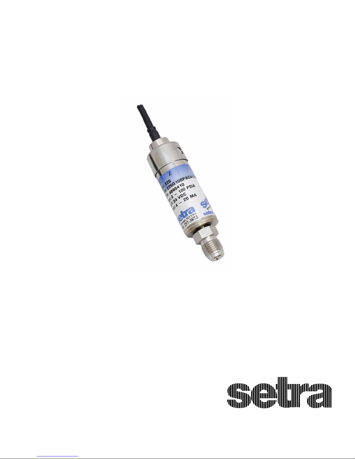
Model 225
Ultra-High Purity
Pressure Transducer
1-800-257-3872 Toll Free
1-978-264-0292 Fax
www.setra.com Web Site
1

Setra Model 225
Ultra High Purity Transducers
1.0 GENERAL INFORMATION
Your Setra Pressure Transducer has been carefully tested and calibrated before shipment. Model 225 performance specications are listed on Page 8 of this guide.
Setra’s 225 pressure transducers sense gauge, compound or absolute pressure and convert this pressure to a
proportional high level analog output. Two output versions are oered: a voltage output of 5 VDC FSO (Full
Scale Output) and 10 VDC FSO, as well as current output of 4 to 20 mA.
NOTE: Latest version of this document may be found at www.setra.com.
1.1 EMC CERTIFICATIONS
This products complies with the latest revision of EN61326-1 and EN61326-2-3 Electrical Equipment for
Measurement, Control and Laboratory use - EMC Requirements for Minimum Requirements and Industrial
Locations. In order to meet EMC compliance the following conditions must be followed:
1. Shielded cable must be used and the shield must be tied to earth ground (not power supply
ground) on at least one end of the cable shield/drain wire. The shield must be maintained all the way
from the sensor to the power supply.
2. If unshielded cable is used, an earth grounded metal conduit tting can be used to replace the
shielded cable.
3. For a sensor with a metal body or enclosure, the body/enclosure must be grounded to earth. If a
protective metal housing is used, the metal housing should be grounded to earth.
2.0 MECHANICAL INSTALLATION
2.1 MEDIA COMPATIBILITY
Model 225 transducer is designed to be used with any gas or liquid compatible with 316L Stainless Steel.
Never submerge the transducer in any liquids.
2.3 PERFORMANCE SPECIFICATIONS
ACCURACY*:
(at constant temperature) ±0.25% FS
Non-Linearity, BFSL ±0.15% FS
Hysteresis 0.20% FS
Non-Repeatability 0.02% FS
*RSS of Non Linearity, Non repeatability & Hysteresis
THERMAL EFFECTS:
Comp Range oF(oC) +15 to +150 (-9 to +65)
Zero Shift %FS/100oF(50oC) 2.0 (1.8)
Span Shift %FS/100oF(50oC 2.0 (1.8)
Warm-Up Shift <±0.1% FS Total
ENVIRONMENTAL DATA:
Operating Temperature oF(oC) -40 to +185 (-40 to 85)
Storage Temperature oF(oC) -40 to +185 (-40 to 85)
Current Unit Ordered with Option N1:
Operating Temperature oF(oC) -22 to +176 (-30 to 80)
Storage Temperature oF(oC) -22 to +176 (-30 to 88)
2
2.3 PRESSURE FITTING
Mounting: Model 225 can be installed with a male or female #4 Face Seal Fitting, 1/4” NPT male or female
tting, or a 1/4” tube stub.
When installed units with Face Seal Fittings:
1. Alight piping systems to transducer connections
2. Hand tighten nuts
3. Torque nuts by placing wrenches on nuts only (or on nut and wrench ats of transducer body for
units xed male face seals)
Never hold the unit by the electronic housing during installation.
Do not over tighten. See technical documents from tting manufacturer for addition instructions.
3.0 ELECTRICAL INSTALLATION
3.1 VOLTAGE OUTPUT UNITS
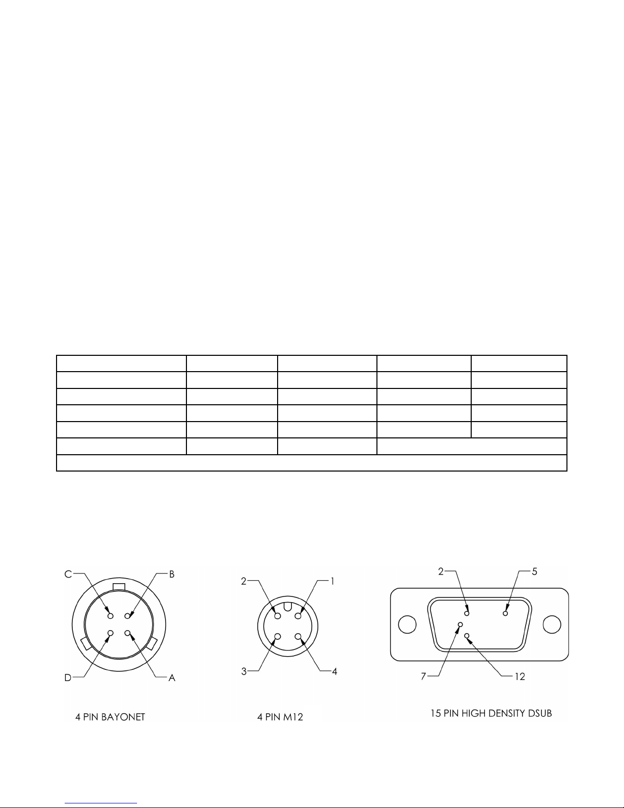
The Model 225 voltage output transducer is supplied with a multi-conductor cable or various style connectors. See Diagram1 & 2 for proper connections.
CONNECTION TABLE FOR VOLTAGE OUTPUT TRANSDUCERS
CONNECTION CABLE WIRE BAYONET PIN 4 PIN M12 15 PIN DSUB
+EXCITATION: RED A 1 7
+OUTPUT: GREEN B 4 2
-OUTPUT: WHITE C 2 5
-EXCITATION: BLACK D 3 12
CASE GND: SHIELDING SHELL
EXCITATION: 10-30 VDC for 0.2 to 5.2 VDC and 0 to 5 VDC & 13-30 VDC for 0.2 to 10.2 VDC and 0 to 10 VDC
DIAGRAM 1
NOTE: “-EXCITATION” and “-OUTPUT” are connected together internally.
DIAGRAM 2: TRANSDUCER PIN OUT
3
 Loading...