

Setra Systems 224 Installation Manual
Installation Guide
1-800-257-3872 Toll Free
1-978-264-0292 Fax
www.setra.com Web Site
Model 224
Ultra-High Purity Flow-Through
Pressure Transducer
ISO
✓
Certified
9001:
2000

2
Setra Model 224
Ultra High Purity Flow-Through Pressure Transducer
1.0 GENERAL INFORMATION
Every Model 224 has been tested and calibrated before shipment. Model 224
performance specifications are listed on Page 6 of this Guide.
Setra Systems 224 pressure transducers sense gauge, compound or absolute
pressure and convert this pressure to a proportional high level analog output.
Two output versions are offered: A voltage output of 5 VDC FSO (Full Scale
Output) and 10 VDC FSO ), and a current output of 4 to 20 mA.
Note: These instructions are also available on our website at www.setra.com.
1.1 EMC Certification
This product complies with EN61326 Electrical Equipment for Measurement,
Control and Laboratory use – EMC Requirements for Minimum Requirements
and Industrial Locations. Special caution should be taken to meet Standard
EN61000-4-5: 1995 Surge Immunity if any of the following conditions apply to
the installation: The product is installed outside; all or any part of the cable is
exposed to the outside; the cable is greater than 30 meters in length. In order
to meet the Surge Immunity requirements, the following conditions must be
followed during installation:
1. Shielded cable must be used, and the shield must be tied to earth ground (not power supply
ground) on at least one end of the cable shield/drain wire. The shield must be maintained all the
way from sensor to the power supply.
2. If unshielded cable is used, an earth grounded metal conduit fitting can be used to replace the
shielded cable.
3. For a sensor with a metal body or enclosure, the body/enclosure must be grounded to earth. If a
protective metal housing is used, the metal housing should be grounded to earth
4. If a protective plastic housing is used, the housing must be able to withstand at least
2 KV from the housing to earth ground, without damaging the circuit.
2.0 MECHANICAL INSTALLATION
2.1 Media Compatibility
Model 224 transducers are designed to be used with any gas or liquid compatible with 316L Stainless Steel. Never submerge the transducers in any liquid.
2.2 Environment
The operating temperature limits of the 224 are as follows:
Operating Temperature Range°F (°C) -40 to +185 (-40 to +85)
Compensated Temperature Range°F (°C) +15 to +150 (-9 to +65)
Current unit ordered with Option N1:
Operating Temperature Range°F (°C) -22 to +176 (-30 to +80)
Compensated Temperature Range°F (°C) +15 to +150 (-9 to +65)
2.3 Pressure Fittings
Mounting - Model 224 pressure transducers can be installed with Face Seal
Fittings or can be butt welded into place.
When installing units with Face Seal Fittings:
a.) Align piping system to transducer connections
b.) Hand tighten nuts
c.) Torque nuts by placing wrenches on nuts only (or on nut and wrench flats
of transducer body for units with fixed male face seals) Never hold the unit
by the electronics housing during installation.
NOTE: Welding purge gases are very hot! It is important to flow hot purge gases away from the
transducer. Disconnect all electrical connections to transducer when welding.
2.4 Venting
Model 224 transducers are vented through the electronics housing.
3.0 ELECTRICAL INSTALLATION
3.1 Voltage Output Units
The Model 224 voltage output transducer is supplied with a 6ft. multiconductor
cable, Bayonet style connector, Mini Din connector, or D-Sub style connectors.
The voltage output is either 5 VDC FSO or 10 VDC FSO. Diagram 1 shows electrical
connection wiring for voltage output transducers, and the excitation required.
Diagram 1
Note: Model 224 can be wired as a 3-wire device by connecting – OUTPUT and –EXCITATION and drain
wire to a common ground. However, accuracy may be reduced due to increase in resistance.
3.2 Current Output Units
The Model 224 is a two-wire loop-powered 4 to 20mA current output unit and
delivers rated current into any external load of 0-800 ohms. The Model 224 is
available with 6ft. of multiconductor cable, Bayonet, Mini Din, or D-Sub style
connectors. Diagram 2 shows electrical connection wiring for current output
transducers.
The power supply must be a DC voltage source with a voltage range between
10 VDC and 30 VDC measured between the + and - terminals. The unit is calibrated
at the factory with a 24 VDC loop supply voltage and a 250 ohm load.
Current must flow in one direction only - Please observe polarity. (See
Diagram 3.) We suggest that the cable shield Drain Wire be connected to the
system’s loop circuit ground for optimum electrical noise rejection. On transducers
with integral connectors (e.g., on Bayonet, D-sub, or MiniDin Connector types),
connection to transducer case ground can be achieved by connecting the cable
drain/shield wire to the mating cable-mounted connector shell (see Note 1).
Diagram 2
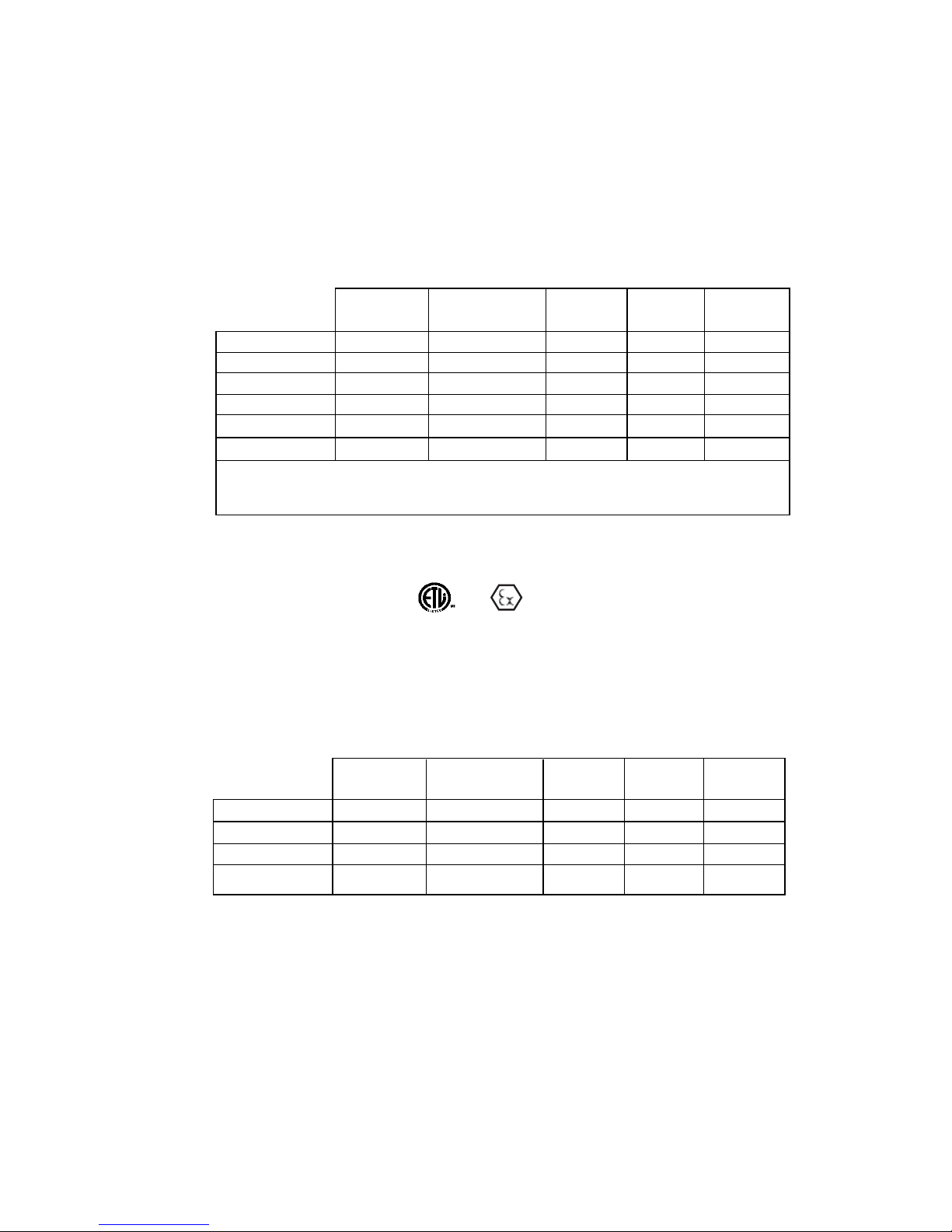
9 PIN 15 PIN 5 PIN
CABLE BAYONET D-SUB D-SUB MINI-DIN
CONNECTION WIRE PIN PIN PIN PIN
+ EXCITATION RED A 4 7 1
+ OUTPUT GREEN B 1 2 2
– OUTPUT WHITE C 8 12 4
– EXCITATION BLACK D 9 5 5
CASE GND DRAIN SHELL SHELL SHELL 3
CONNECTOR PIN WIRING FOR VOLTAGE TRANSDUCERS
CONNECTOR PIN WIRING FOR CURRENT TRANSMITTERS
EXCITATION: 10-30 VDC FOR 0.2 TO 5.2 VDC and 0 to 5 VDC
13-30 VDC FOR 0.2 TO 10.2 VDC and 0 to 10 VDC
Minimum Supply Voltage = 10 + 0.02 x Loop Resistance
Maximum Supply Voltage = 30 + 0.004 x Loop Resistance
9 PIN 15 PIN 5 PIN
CABLE BAYONET D-SUB D-SUB MINI-DIN
CONNECTION WIRE PIN PIN PIN PIN
+ EXCITATION RED A 4 7 1
– EXCITATION BLACK D & B 9 5 4
CASE GND DRAIN SHELL SHELL SHELL 3
3
and
w/N1 option, see Notes 2 and 3, Page 4.)
(
 Loading...