

Page 1

Installation Guide
Setra Systems Model 265
Differential Pressure Transducer
1.0 GENERAL INFORMATION
Every Model 265 has been tested and calibrated before shipment. Specific
performance specifications are shown on page 3 of this Guide.
Setra Systems 265 pressure transducers sense differential or gage (static) pres-
sure and convert this pressure difference to a proportional high level analog
output for both unidirectional and bidirectional pressure ranges. The Model
265 is available in the following excitation and output versions:
Excitation Output
9-30 VDC 0-5 VDC
9-30 VAC 0-5 VDC
12-30 VAC 0-10 VDC
9-30 VDC (measured between the + and - terminals) 4-20 mA
Check the label on the unit to confirm the excitation and ouput.
2.0 MECHANICAL INSTALLATION
2.1 Media Compatibility
Model 265 transducers are designed to be used with air or nonconducting
gases. Use with liquids or corrosive gases will damage the unit.
2.2 Environment
The operating and compensated temperature limits of the 265 are 0°F to
+150°F (-18°C to +65°C).
2.3 Pressure Fittings
The Model 265 is supplied with two factory installed 1/4” O.D. pressure
fittings for the pressure signal connection and typically installed with 1/4”
push-on tubing. Both the positive (high) pressure port and the reference (low)
pressure port are located on the front of the unit, labeled “HIGH” and “LOW”
respectively. For best results (shortest response times), 3/16” I.D. tubing is
suggested for tubing lengths up to 100 feet long, 1/4” I.D. for tubing lengths
up to 300 feet, and 3/8” I.D. for tubing lengths up to 900 feet.
3.0 ELECTRICAL INSTALLATION
If the Model 265 is supplied with the optional Conduit Enclosure, access the
electrical terminations by removing the cover.
For CE compliance a shielded cable with both ends properly grounded is
required.
3.1 Voltage Output Units
The Model 265 voltage output is a 3-wire circuit, with three terminals avail-
able for wiring. These terminals have the designation COM, OUT and EXC (see
Diagram 1). [Note: The - designation above COM and the + designation above
EXC are designations for the current output terminals.] The -Excitation and
-Output are commoned on the circuit (see Diagram 2). The 265 voltage output
can operate from 9-30 VDC or 9-30 VAC excitation with 0-5 VDC output, or 12-
30 VAC excitation with 0-10 VDC output.
Page 2
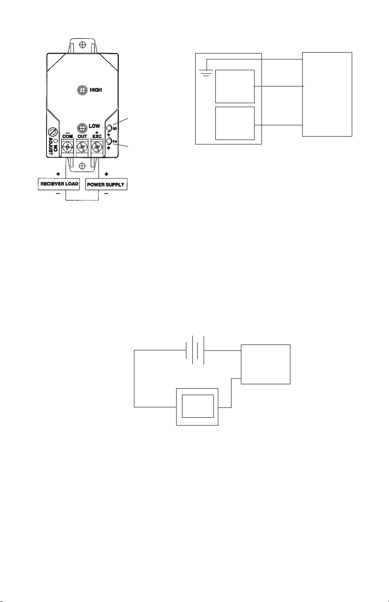
Diagram 1
Voltage Circuit Diagram
- COM
Readout
or
DAS
OUT
Model
265
SPAN
ADJUSTMENT
ZERO
ADJUSTMENT
Power
Supply
+ EXC
Diagram 2
+EXC Connected to positive terminal of DC/AC
power supply
-COM Connect as the reference for power
supply and output signal
OUT Connect to positive terminal of control
or pressure
3.2 Current Output Units
The Model 265 is a two-wire loop-powered 4 to 20mA current output unit (see
Diagram 3). The current flows into + terminal and returns back to the power
supply through the - terminal (see Diagram 3). The power supply must be a DC
voltage source with a voltage range between 9 and 30 measured between
terminal + and - terminals. The unit is calibrated at the factory with a 24 VDC
loop supply voltage and a 250 ohm load.
CurrentCircuit Diagram
9 to 30 VDC+_
Current
Monitoring
Device
265
4.0. CALIBRATION
The 265 transducer is factory calibrated and should require no field adjust ment. Generally, the mounting position will have a zero shift effect on ranges
below 1” WC. Whenever possible, any zero and/or span offsets should be
corrected by software adjustment in the user’s control system. However, both
zero and span adjustments are accessible either on the front of the unit or by
removing the optional conduit enclosure. The 265 transducer is calibrated in
the vertical position at the factory.
4.1 Voltage Output Zero Adjustment
While monitoring the voltage between the positive output (OUT) and
common (COM), and with both pressure ports open to atmosphere, the zero
may be adjusted by turning the zero adjustment screw. (See Diagram 1 for
2
Page 3

location of zero adjustment.) For 0-5 VDC output units, the factory settings
are 0.0VDC (±50mV) for unidirectional pressure ranges and 2.5VDC (±50mV)
for bidirectional pressure ranges. Optional outputs are set at the same ±1%
factory setting.
4.2 Voltage Output Span Adjustment (Complete the zero adjustment
before setting span.)
Span or full scale output adjustments should only be performed by using an
accurate pressure standard (electronic manometer, digital pressure gage, etc.),
with at least comparable accuracy to the 265 transducer (<±1% FS). With full
range pressure applied to the high pressure port (reference port open to atmosphere), the span may be adjusted by turning the SPAN adjustment screw. (See
Diagram 1 for location of the SPAN adjustment.) For 0-5 VDC output units, the
factory settings are 5.0 VDC (±50mV) for unidirectional and bidirectional ranges.
Optional outputs are set at the same ±1% factory setting.
4.3 Current Output Zero Adjustment
While monitoring the current output between +EXC and OUT, and with both
pressure ports open to atmosphere, the zero may be adjusted by turning the
zero adjustment screw. (See Diagram 1 for location of zero adjustment.) The
factory settings are 4mA (0.16mA) for unidirectional pressure ranges and 12mA
(0.16mA) for bidirectional ranges.
4.4 Current Output Span Adjustment
Span or full scale output adjustments should only be performed by using an
accurate pressure standard (electronic manometer, digital pressure gage,
etc.) with at least comparable accuracy to the 265 transducer (<±1% FS). With
full range pressure applied to the high pressure port (reference port open to
atmosphere), the span may be adjusted by turning the SPAN adjustment screw.
(See Diagram 1 for location of SPAN adjustment.) The factory settings are 20mA
(0.16mA) for unidirectional and bidirectional pressure ranges.
5.0 MODEL 265 PERFORMANCE SPECIFICATIONS
Accuracy RSS* ±1.0% FS Thermal Effects
(at constant temperature.) Compensated Range °F(°C) 0 to +150 (-18 to +65)
Non-Linearity, BFSL ±0.98% FS Zero/Span Shift %FS/°F(°C) 0.033 (0.06)
Hysteresis 0.1% FS Maximum Line Pressure 10 psi
Non-Repeatability 0.05% FS Overpressure 10 psi in positive or
*RSS of Non-Linearity, Non-Repeatability negative direction
and Hysteresis. Warm-up Shift ±0.1% FS total
Position Effects
(Unit is factory calibrated at 0g effect in the vertical position)
Range Zero Offset (%FS/G)
0 to 1” WC .22
0 to 5” WC .14
0 to 30” WC .06
3
Page 4

6.0 RETURNING PRODUCTS FOR REPAIR
Please contact a Setra application engineer (800-257-3872, 978-263-1400) before
returning unit for repair to review information relative to your application. Many times
only minor field adjustments may be necessary. When returning a product to Setra,
the material should be carefully packaged and shipped prepaid to:
Setra Systems, Inc.
159 Swanson Road
Boxborough, MA 01719-1304
Attn: Repair Department
To assure prompt handling, please supply the following information and include it
inside the package or returned material:
1. Name and phone number of person to contact.
2. Shipping and billing instructions.
3. Full description of the malfunction.
4. Identify any hazardous material used with product.
Notes: Please remove any pressure fittings and plumbing that you have installed and
enclose any required mating electrical connectors and wiring diagrams.
Allow approximately 3 weeks after receipt at Setra for the repair and return of the unit.
Non-warranty repairs will not be made without customer approval and a purchase
order to cover repair charges.
Calibration Services
Setra maintains a complete calibration facility that is traceable to the National Institute
of Standards & Technology (NIST). If you would like to recalibrate or recertify your
Setra pressure transducers or transmitters, please call our Repair Department at 800257-3872 (978-263-1400) for scheduling.
7.0 WARRANTY AND LIMITATION OF LIABILITY
SETRA warrants its Model 265 Transducer products to the original consumer purchaser against defects for a
period of one year from the date of sale by SETRA, as shown in its shipping documents.
Without charge, SETRA will repair or replace products found to have manufacturing defects within the warranty
period.
The serial number or date code must not have been removed, defaced or otherwise changed.
SETRA must be notified in advance of any returns; any products returned to SETRA must be transportation
prepaid.
The foregoing warranty is in lieu of all warranties, express, implied or statutory, including but not limited to, any
implied warranty of merchantability for a particular purpose.
SETRA’s liability for breach of warranty is limited to repair or replacement, or if the goods cannot be repaired
or replaced, to a refund of the purchase price. SETRA’s liability for all other breaches is limited to a refund of
the purchase price. In no instance shall SETRA be liable for incidental or consequential damages arising from a
breach of warranty, or from the use or installation of its products.
No representative or person is authorized to give any warranty other than as set out above or to assume for
SETRA any other liability in connection with the sale of its products.
For all CE technical questions, contact Setra Systems, USA. EU customers may contact our EU representative,
Hengstler GmbH, Uhlandstr, 49, 78554 Aldingen, Germany (Tel: +49-7424-890; Fax: +49-7424-89500)
159 Swanson Road, Boxborough, MA 01719-1304
Tel: 800-257-3872/978-263-1400
4
SS2009 Rev.G 08/25/09
 Loading...