

Page 1
Installation Guide
ISO
9001:
2000
Certified
✓
1-800-257-3872 Toll Free
1-978-264-0292 Fax
www.setra.com Web Site
Page 2

Setra offers a complete line of
products for these industries:
Industrial
HVAC
Test & Measurement
Barometric
Ultra High Purity/Sanitary
Page 3

Table of Contents
1.0 GENERAL INFORMATION ............................................................................................... 4
2.0 MECHANICAL INSTALLATION ...................................................................................... 4
2.1 Media Compatibility .......................................................................................... 4
2.2 Environment ......................................................................................................... 4
2.3 Pressure Fittings .................................................................................................. 4
2.4 Moisture Precautions ........................................................................................ 4
2.5 Venting ................................................................................................................... 4
2.6 Mounting Accessories....................................................................................... 5
3.0 ELECTRICAL INSTALLATION .......................................................................................... 5
3.1 Voltage Output Units ......................................................................................... 5
3.2 Current Output Units ........................................................................................ 6
4.0. CALIBRATION .................................................................................................................... 6
4.1 Voltage Output Zero Adjustment ................................................................. 6
4.2 Voltage Output Span Adjustment ................................................................ 7
4.3 Current Output Zero Adjustment ................................................................. 7
4.4 Current Output Span Adjustment ................................................................ 7
5.0 MODEL 256 PERFORMANCE SPECIFICATIONS ....................................................... 7
6.0 RETURNING PRODUCTS FOR REPAIR ......................................................................... 8
7.0 WARRANTY AND LIMITATION OF LIABILITY............................................................ 8
Page 4

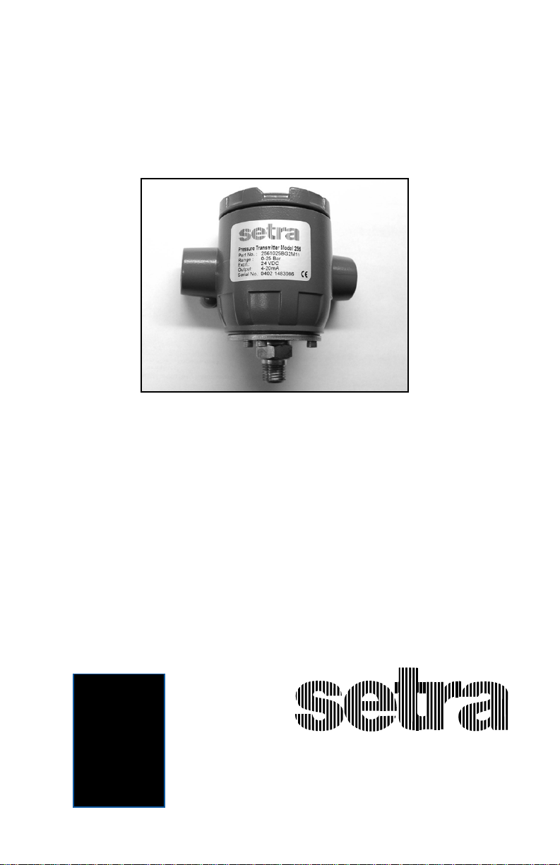
Setra Model 256
Pressure Transducer
1.0 GENERAL INFORMATION
Every Model 256 has been tested and calibrated before shipment. Specific
performance specifications are listed on Page 7 of this Guide.
Setra Systems 256 pressure transducers sense gage pressure and convert this
pressure to a proportional high level analog output. Two output versions are
offered: A voltage output of .1 to 5.1 VDC, and a current output of 4 to 20 mA.
2.0 MECHANICAL INSTALLATION
2.1 Media Compatibility
Model 256 transducers are designed to be used with any gas or liquid compatible with 17-4 PH Stainless Steel. (Hydrogen is not recommended for use with
17-4 PH SS.)
2.2 Environment
The operating temperature limits of the 256 are as follows:
Operating Temperature Range °F (C°) -40 to +185 (-40 to +85)
Compensated Temperature Range°F (C°) -4 to +176 (-20 to +80)
2.3 Pressure Fittings
Typically, standard pipe fittings and installation procedures should be used.
However, for very high pressure ranges in excess of 500 psig, we suggest the
use of a sealant such as Loctite Hydraulic Sealant. Excessive high torquing of
metal fittings may cause a slight shift of the output, but this shift can be
trimmed out by the zero adjustment. Torquing does not significantly affect
linearity or sensitivity.
2.4 Moisture Precautions
The Model 256 is provided with two 1/2” NPT female conduit ports for electrical
termination. These tapered pipe threads are tapped deeper than the NPT
standard, in accordance with industry guidelines. These ports must be sealed
according to standard industry practice, in order to prevent moisture ingress
into the Model 256.
2.5 Venting
The Model 256 is a true gage pressure transducer. This means that the
reference side of the pressure sensing diaphragm must be vented to atmosphere. If the reference side of the diaphragm were sealed (as in a sealed gage
transducer), temperature changes would cause the reference pressure to vary.
This may affect the overall accuracy, especially in ranges lower than 500 psig.
The Model 256 provides a vent from the reference side of the sensor to the
inside of the housing and the conduit ports. The user-provided electrical
conduit must be vented to atmosphere in a clean dry location. (It is important
to prevent moisture ingress from the environment into the wiring chamber
or reference side of the transducer.)
4
Page 5

2.6 Mounting Accessories
The Model 256 is provided with a bracket
and two hex bolts for mounting and a 1/2”
NPT plug for the unused conduit opening.
The bracket is suitable for mounting with a U-
bolt or a band clamp. There are 1/4-20 UNC
threaded holes on the back of the 256
transducer for direct mounting and/or
grounding.
3.0 ELECTRICAL INSTALLATION
Wiring is through a 1/2” conduit opening. Remove
the screw cover to access the removable wiring
terminal block connector. The terminal block
connector version has five terminals for wiring
+EXC, -EXC, GND, -OUT, and +OUT (see Diagram 1).
Remove the terminal block connector to facilitate wiring to screw terminals.
Refer to the terminal block connector label for terminal designations. (See
Diagram 2 for screw terminal designations.) After wiring, plug connector back
into pin socket and neatly tuck all wiring into wire recess cavity.
Diagram 2
Diagram 1
Screw Terminal
Designations
+ EXC
EXC
Voltage Connections
+ EXC
Removable
Zero/Span
Access Plugs
Removable
Terminal Block
Connector
Current Connections
EXC
3.1 Voltage Output Units
The Model 256 is a 3-wire circuit. The -EXC and -OUT are commoned on the
circuit. The 256 can operate from a 12 to 28 VDC excitation. The 256 has a 0.1-
5.1 VDC output.
+ Excitation; connect to 12-28 VDC power supply
+ Output; connect to controller or monitor
– Output; connect to controller or monitor
– Excitation; connect to return of 12-28 V power supply
GND Connect to system or earth ground
The Model 256 can be wired as a three wire device by connecting – output,
excitation and shield to a common ground. However, accuracy will be reduced
with increase in lead resistance.
GND
OUT
GND
+ OUT
5
Page 6

3.2 Current Output Units
The 4-20 mA current output units are designed to have current flow in one
direction only - PLEASE OBSERVE POLARITY.
We suggest that the electrical conduit shield be connected to the system’s loop
circuit ground to improve electrical noise rejection.
The Model 256 is a two-wire loop-powered 4 to 20mA current output unit and
delivers rated current into any external load of 0-800 ohms. (See Diagram 2 for
location of +EXC and -EXC current output screw terminals.) The current flows
into the + terminal and returns back to the power supply through the
- terminal. (The center GND terminal may be used for shielding.) The power
supply must be a DC voltage source with a voltage range between 9 and 30
measured between the + and - terminals. The unit is calibrated at the factory
with a 24 VDC loop supply voltage and a 250 ohm load.
Minimum Supply Voltage (VDC) = 9 + 0.02 x (resistance of receiver plus line).
Maximum Supply Voltage (VDC) = 30 + 0.004 x (resistance of receiver plus line).
4.0 CALIBRATION
The 256 transducer is factory calibrated and should require no field
adjustment. Whenever possible, any zero and/or span offsets should be
corrected by software adjustment in the user’s control system. However, both
zero and span adjustments are accessible by removing the screw top cover and
the adjustment access cover and turning the potentiometer screw inside. (See
Diagram 1 for the location of the Zero and Span potentiometers.)
4.1 Voltage Output Zero Adjustment
While monitoring the voltage between the positive output (+OUT) and
negative output (– OUT), and with the pressure port open to atmosphere, or
with zero pressure applied, the zero may be adjusted by turning the zero
potentiometer screw. The factory setting is 0.1 VDC (±25mV).
Note: –OUT and –EXC are commoned on the circuit.
4.2 Voltage Output Span Adjustment (Complete the zero adjust ment before setting span.)
Span or full scale output adjustments should only be performed by using an
accurate pressure standard (electronic manometer, digital pressure gage, etc.),
with at least comparable accuracy to the 256 transducer. With full
range pressure applied to the pressure port, the span may be adjusted by
turning the span potentiometer screw. The factory setting is 5.1 VDC (±50mV).
6
Page 7

4.3 Current Output Zero Adjustment
While monitoring the current output, and with the pressure port open to
atmosphere or with zero pressure applied, the zero may be adjusted by turning
the zero potentiometer screw. The factory setting is 4mA (±.08mA).
4.4 Current Output Span Adjustment
Span or full scale output adjustments should only be performed by using an
accurate pressure standard (electronic manometer, digital pressure gage, etc.)
with at least comparable accuracy to the 256 transducer. With full range
pressure applied to the pressure port, the span may be adjusted by turning the
span potentiometer screw. The factory setting is 20mA (±.16mA).
5.0 MODEL 256 PERFORMANCE SPECIFICATIONS
For Ranges For Ranges
25 PSI and Higher Less Than 25 PSI
Accuracy RSS* (at constant temperature.) ±.13% FS ±0.25% FS
Non-Linearity, BFSL ±0.1% FS ±0.22% FS
Hysteresis 0.08% FS 0.10% FS
Non-Repeatability 0.02% FS 0.05% FS
*RSS of Non-Linearity, Non-Repeatability and Hysteresis.
Thermal Effects
Compensated Range °F(°C) -4 to +176 (-20 to +80) -4 to +176 (-20 to +80)
Zero Shift %FS/100°F (50°C) ±1.0 (± 0.9) ±2.0 (± 1.8)
Span Shift %FS/100°F (50°C) ±1.5 (±1.4) ±1.5 (± 1.3)
Warm-up Shift ±0.1% FS total ±0.1% FS total
7
Page 8

6.0 RETURNING PRODUCTS FOR REPAIR
Please contact a Setra Systems application engineer (1-800-257-3872, 1-978-263-1400)
before returning unit for repair to review information relative to your application.
Many times only minor field adjustments may be necessary. When returning a product
to Setra Systems, the material should be carefully packaged and shipped prepaid to:
Setra Systems, Inc.
159 Swanson Road
Boxborough, MA 01719-1304
Attn: Repair Department
To assure prompt handling, please supply the following information and include it
inside the package or returned material:
1. Name and phone number of person to contact.
2. Shipping and billing instructions.
3. Full description of the malfunction.
4. Identify any hazardous material used with product.
Notes: Please remove any pressure fittings and plumbing that you have installed and
enclose any required mating electrical connectors and wiring diagrams.
Allow approximately 3 weeks after receipt at Setra Systems for the repair and return of
the unit. Non-warranty repairs will not be made without customer approval and a
purchase order to cover repair charges.
Calibration Services
Setra maintains a complete calibration facility that is traceable to the National Institute
of Standards & Technology (NIST). If you would like to recalibrate or recertify your
Setra pressure transducers or transmitters, please call our Repair Department at 800257-3872 (978-263-1400) for scheduling.
7.0 WARRANTY AND LIMITATION OF LIABILITY
SETRA warrants its products to be free from defects in materials and workmanship, subject to the following terms and conditions: Without charge, SETRA will repair or replace
products found to be defective in materials or workmanship within the warranty period; provided that:
a) the product has not been subjected to abuse, neglect, accident, incorrect wiring not our own, improper installation or servicing, or use in violation of instructions
furnished by SETRA;
b) the product has not been repaired or altered by anyone except SETRA or its authorized service agencies;
c) the serial number or date code has not been removed, defaced, or otherwise changed; and
d) examination discloses, in the judgment of SETRA, the defect in materials or workmanship developed under normal installation, use and service;
e) SETRA is notified in advance of and the product is returned to SETRA transportation prepaid.
Unless otherwise specified in a manual or warranty card, or agreed to in writing and signed by a SETRA officer, SETRA pressure and acceleration products shall be warranted for
one year from date of sale.
The foregoing warranty is in lieu of all warranties, express, implied or statutory, including but not limited to, any implied warranty of merchantability for a particular purpose.
SETRA’s liability for breach of warranty is limited to repair or replacement, or if the goods cannot be repaired or replaced, to a refund of the purchase price. SETRA’s liability for all
other breaches is limited to a refund of the purchase price. In no instance shall SETRA be liable for incidental or consequential damages arising from a breach of warranty, or
from the use or installation of its products.
No representative or person is authorized to give any warranty other than as set out above or to assume for SETRA any other liability in connection with the sale of its
products.
159 Swanson Road, Boxborough, MA 01719
8
Toll Free: (800) 257-3872, Fax: (978) 264-0292
SS2033 Rev.G 05/23/07
 Loading...