

Page 1
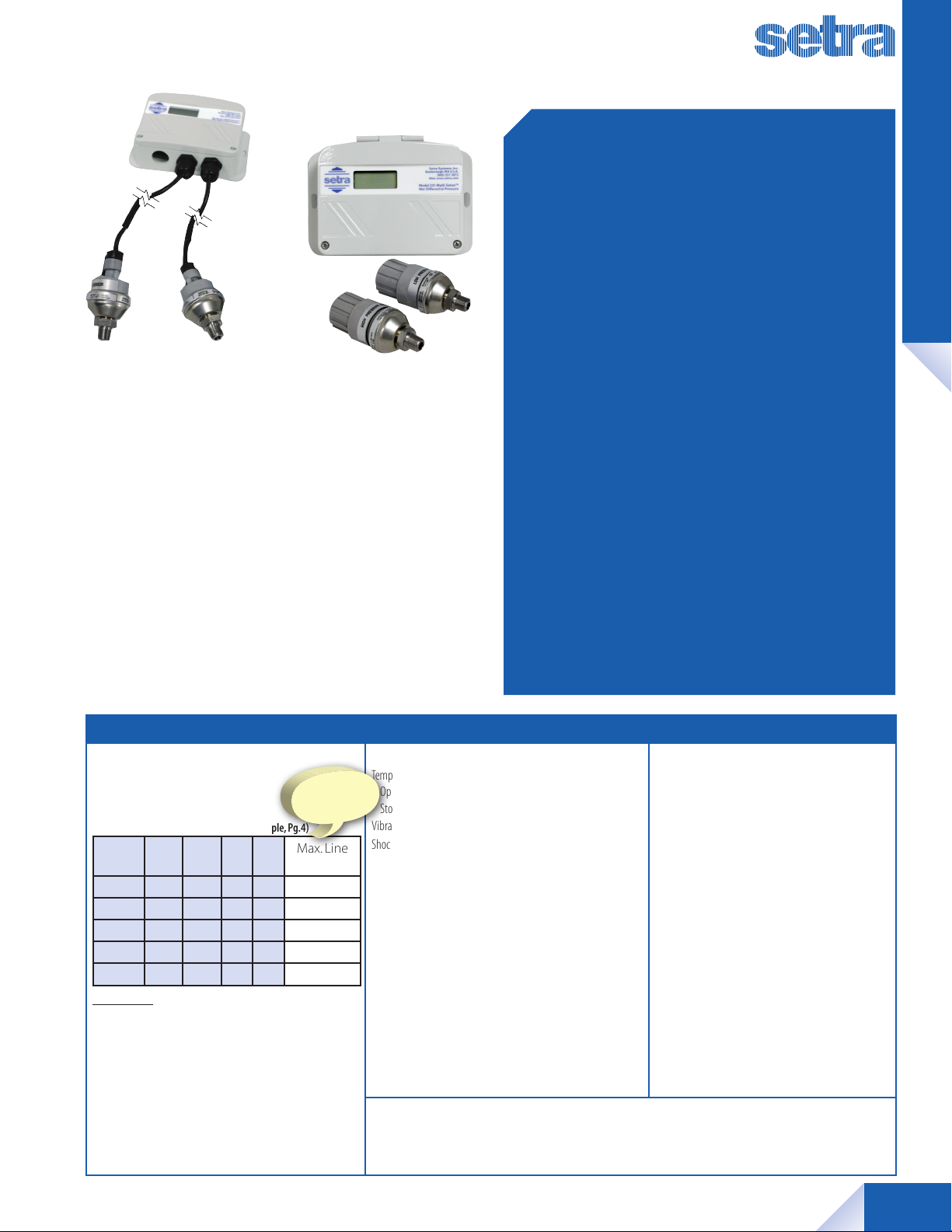
Multi-Sense® Model 231RS
Wet-to-Wet, Differential, Multi-Configurable Pressure Transducer
231RS Cable Version
FEATURES
■ Wet-to-Wet Transducer w/ Remote Sensors
■ Conduit and Cable Versions
■ Field Selectable Output - True 4 to 20 mA,
0 to 5, 1 to 5, and 0 to 10 VDC
231RS Conduit Version
Industry First Wet-to-Wet
Remote Sensor Design
DESCRIPTION
etra’s 231RS with remote sensors reduces labor, materials,
and time. The sensors are installed directly into the pipe
S
and electrical connection is made between the remote
sensors and the Model 231RS via cables or conduit, reducing
labor cost by one-third and the cost of copper to connect the
pressure transducer to the pipe. Startup time is reduced since
purging air out of the lines is not necessary.
The Multi-Sense® Model 231 Wet-to-Wet differential pressure transducer’s all inclusive design provides users with field
accessible ranging, choice of output and field zeroing.
NOTE: Setra quality standards are based on ANSI-Z540-1.
The calibration of this product is NIST traceable.
■ Each Unit Provides 4 Unidirectional and 4
Bidirectional Switch Selectable Pressure
Ranges
■ Field Accessible Push-Button Zero and
Remote Zero
■ Jumper Selectable Port Swap
■ Optional LCD
■ All Cast Aluminum, NEMA4 Rated Housing
■ CE and RoHS Compliant
APPLICATIONS
■ Energy Management Systems
■ Process Control Systems
■ Flow Measurement of Various Gases or
Liquids
■ Liquid Level Measurement of Pressurized
Vessels
DIFFERENTIAL PRESSURE
SPECIFICATIONS
Performance Data
Accuracy RSS1 (at constant temp.)
Pressure Ranges A, B, C ±1.0% FS
Pressure Range D ±2.0% FS
Pressure Ranges (Selection Example, Pg.4)
Range
Code
RS1 50 25 10 5 50
RS2 75 37.5 15 7.5 75
RS3 100 50 20 10 100
RS4 150 75 30 15 150
RS5 250 125 50 25 250
Thermal Effects
Compensated Range °F (°C) +32 to +130 (0 to +54)
Zero Shift %FS/100°F (50°C) 2.0 (1.8)
Span Shift %FS/100°F(50°C) 2.0 (1.8)
Warm-up Shift <0.12% FS
Response Time 1 to 5 sec. (selectable )
Proof Pressure 2 x Full Scale
Burst Pressure 15 x Full Scale (50 psi)
10 X Full Scale (75 x 150 psi)
8 x Full Scale (250 psi)
A B C D Max. Line
2
Line Pressure
Determines
Selection of Range
Code
Pressure
Environmental Data
Temperature
Operating3 °F (°C) -4 to +185(-20 to +85)
Storage °F (°C) -4 to +185(-20 to +85)
Vibration 10g from 50 Hz to 2000 Hz
Shock 200g
Physical Description
Case Die Cast Aluminum, Powder
Coated
Pressure Fittings 1/4-18 NPT Male
Electrical Connection 1/2 in. Conduit
Size 4.0 x 6 x 2 in.
(102 x 152 x 51mm)
Weight 1.3 lb (Case Only)
Pressure Media
Liquids or Gases Compatible with 17-4 PH Stainless Steel
Note: Hydrogen not recommended for use with 17-4 PH stainless
steel.
1
RSS of Non-Linearity, Hysteresis, and Non-Repeatability.
2
Units calibrated at nominal 70˚F. Maximum thermal error computed from
this datum.
3
Operating temperature limits of the electronics only. Pressure media
temperatures may be considerably higher or lower.
Electrical Data (Voltage)
Circuit 3-Wire
Excitation 15 to 30 VDC/18 to 30 VAC
(Reverse Excitation Protected)
Output4 0 to 5 VDC
0 to 10 VDC
1 to 5 VDC
Output Impedance 30 Ohms
Current Consumption 8 mA (typ.) at 5 VDC
8 mA (typ.) at 10 VDC
40 mA (typ.) at 18-30 VAC
Electrical Data (Current)
Circuit 2-Wire
(Reverse Excitation Protected)
Output5 4 to 20 mA
External Load 0 to 250 Ohms
Minimum supply voltage (VDC ) = 15 + 0.02 x (Resistance
of receiver plus line).
Maximum supply voltage (VDC) = 30 + 0.004 x
(Resistance of receiver plus line).
4
Calibrated into a 50K ohm load, operable into a 5000 ohm load
or greater.
5
Calibrated at factory with a 24 VDC loop supply voltage and a
250 ohm load.
Specifications subject to change without notice.
©2011 Setra Systems, Inc. All rights reserved. The Setra Systems name and logo are registered trademarks of Setra Systems, Inc. Phone: 800-257-3872 • Fax: 978-264-0292 • setra.com
1
Page 2
Multi-Sense® Model 231RS
Wet-to-Wet, Differential, Multi-Configurable Pressure Transducer
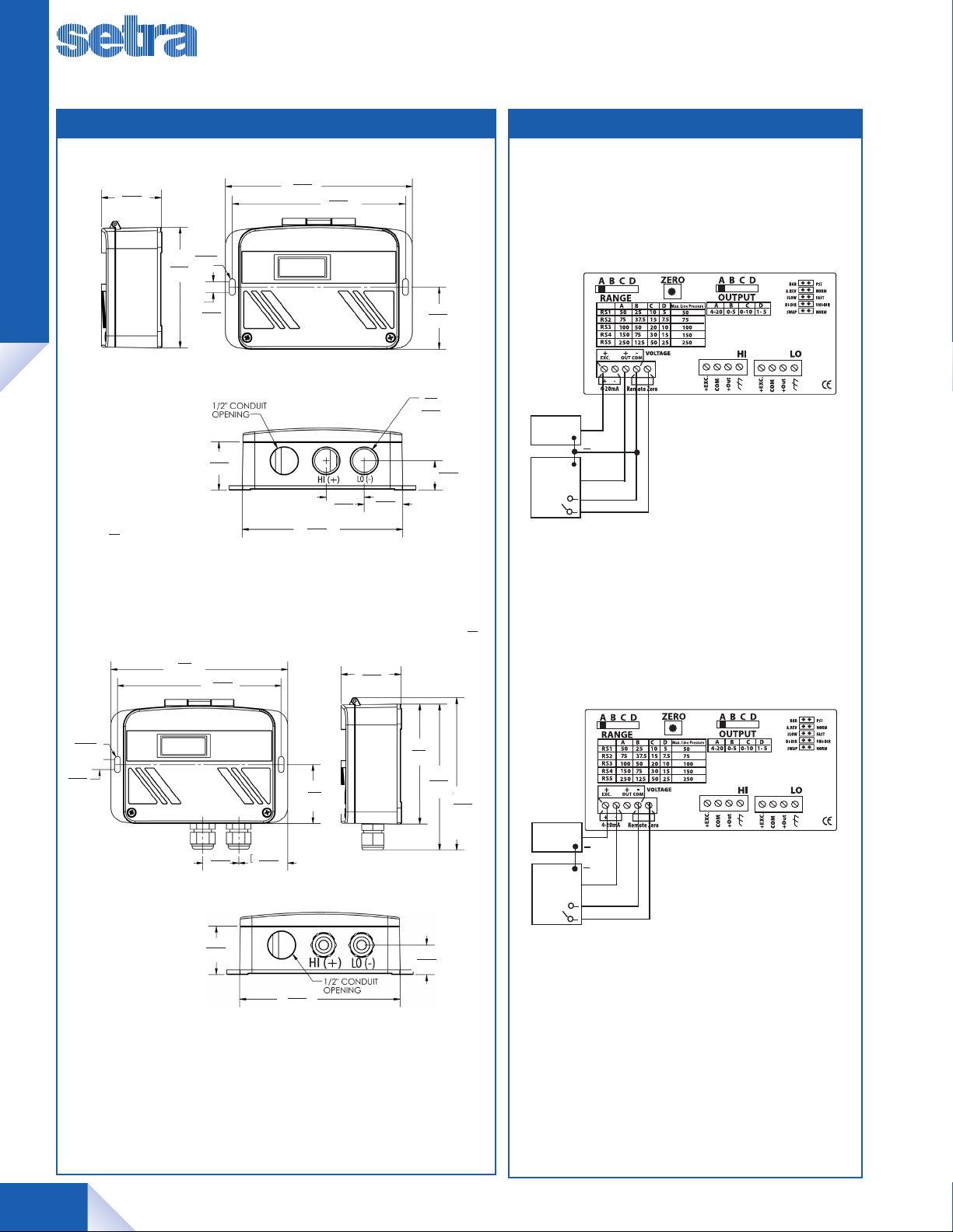
WIRINGDIMENSIONS
DIFFERENTIAL PRESSURE
1.98
50.3
Side View
IN
MM
4.00
102.0
6.0
152.4
R 0.1
2.5
0.35
8.8
1.56
39.6
141.2
Conduit Version
5.56
6.00
152.4
5.56
141.2
Front View
1.22
30.9
5.16
131.1
Bottom View
1.98
50.3
1.24
31.5
2 x
0.86
21.9
2.00
50.8
0.95
24.1
IN
MM
DC/AC
Power Supply
Controller
Voltage
Relay
+
+
3-Wire - Voltage Output
0 to 5 VDC
0 to 10 VDC
1 to 5 VDC
Remote Zero
R 0.1
0.35
8.8
2.5
1.22
31.0
Front View
1.56
39.6
2.0
50.8
1.66
42.2
5.16
131.1
Bottom View
Cable Version
4.0
102
Side View
0.95
4.87
123.6
5.08
129.0
DC Power
Supply
Controller
Current
(4-20 mA)
Relay
SSP231RS Rev.A 09/14/111
+
+
2-Wire - Current Output
4 to 20 mA
Remote Zero
2
Phone: 800-257-3872 • Fax: 978-264-0292 • setra.com ©2011 Setra Systems, Inc. All rights reserved. The Setra Systems name and logo are registered trademarks of Setra Systems, Inc.
Page 3

Multi-Sense® Model 231RS
Wet-to-Wet, Differential, Multi-Configurable Pressure Transducer
DIFFERENTIAL PRESSURE
DIMENSIONS
3.61
91.7
1.68
42.5
1/2 inch Conduit Opening
1.40
35.48
1.62
41.2
3/4” HEX
1/4” NPT
IN
MM
WIRING
Terminal Block
(CN8 & CN11)
4
3
2
1
(GND)
+OUT
COM
+EXC
Transducer w/Conduit
Conduit Adapter
Transducer w/Conduit
1.46
37.1
3.00
76.0
1.62
41.2
IN
MM
0.325
8.3
Terminal Block
(CN8 & CN11)
4
(Shield)
3
+OUT (White) C
2
COM (Black) A
1
+EXC (Red) B
3-Pin Packard
Transducer w/Pack ard Connector
Connector
Transducer w/Pack ard Connector
©2011 Setra Systems, Inc. All rights reserved. The Setra Systems name and logo are registered trademarks of Setra Systems, Inc. Phone: 800-257-3872 • Fax: 978-264-0292 • setra.com
3
Page 4

INSTALLATION
Multi-Sense® Model 231RS
Wet-to-Wet, Differential, Multi-Configurable Pressure Transducer
Model 231RS
DIFFERENTIAL PRESSURE
Valve A
High
High Pressure
Remote Sensor
1
Valve A = High Side Valve
Valve B = Low Side Valve
Pipe
1. Valves not included.
Low Pressure
Remote Sensor
Pipe
PRESSURE RANGE CODE SELECTOR (IMPORTANT: READ BEFORE ORDERING)
Examine the pressure application and determine what is the Highest System Line Pressure.
Determine what is the Differential Pressure being measured.
Find the MAX. Line Pressure in the table on the right that is > to your Highest System Line Pressure.
Verify that your DP falls within the selectable ranges in that row.
Follow that row to the left and select that range code.
Example: Highest System Line Pressure: 125 psig
Range
Code
RS1 50 25 10 5 50
RS2 75 37.5 15 7.5 75
RS3 100 50 20 10 100
RS4 150 75 30 15 150
RS5 250 125 50 25 250
Differential Pressure Measured: 75 psid
“Max Line Pressure” ≥ to System Line Pressure: 150 psid (75 psid DP falls within ranges in this row)
Select Range Code: RS4
A B C D Max. Line
Valve B
Low
1
Line Pressure
Determines
Selection of Range
Code
Pressure
ORDERING INFORMATION
2 3 1 G
Model Range Code Pressure Connection Display Cable
231G = 231RS See Table 1 Below 3M 1/4-18 NPT Male Remote Sen-
sor (Conduit Version)
4M 1/4-18 NPT Male Remote Sen-
sor (Cable Version)
Ordering Example: 231GRS44MN10 = Model 231RS w/Range Code RS4, 1/4-18 NPT Male Remote Sensor
(Cable Version) , No Display, 10ft. Cable
Table 1. Range Specifi cation
2
UNIDIRECTIONAL PRESSURE RANGES BIDIRECTIONAL PRESSURE R ANGES
5, 10, 25, 50 psid ±5, ±10, ±25, ±50 psid
15, 30, 75, 150 psid ±15, ±30, ±75, ±150 psid
25, 50, 125, 250 psid ±25, ±50, ±125, ±250 psid
4
RANGE CODE
RS1
RS2 7.5, 15, 37.5, 75 psid ±7.5, ±15, ±37.5, ±75 psid
RS3 10, 20, 50, 100 psid ±10, ±20, ±50, ±100 psid
RS4
RS5
1. Cable lengths only available with Pressure Connection Code 4M. 2. For higher ranges contact factory.
Phone: 800-257-3872 • Fax: 978-264-0292 • setra.com ©2011 Setra Systems, Inc. All rights reserved. The Setra Systems name and logo are registered trademarks of Setra Systems, Inc.
1
Std. N No Display Std. 10 10ft
SSP231RS RevB 08/30/11
Opt. D LCD Display Opt. 20 20ft
Opt. 30 30ft
 Loading...