

Page 1
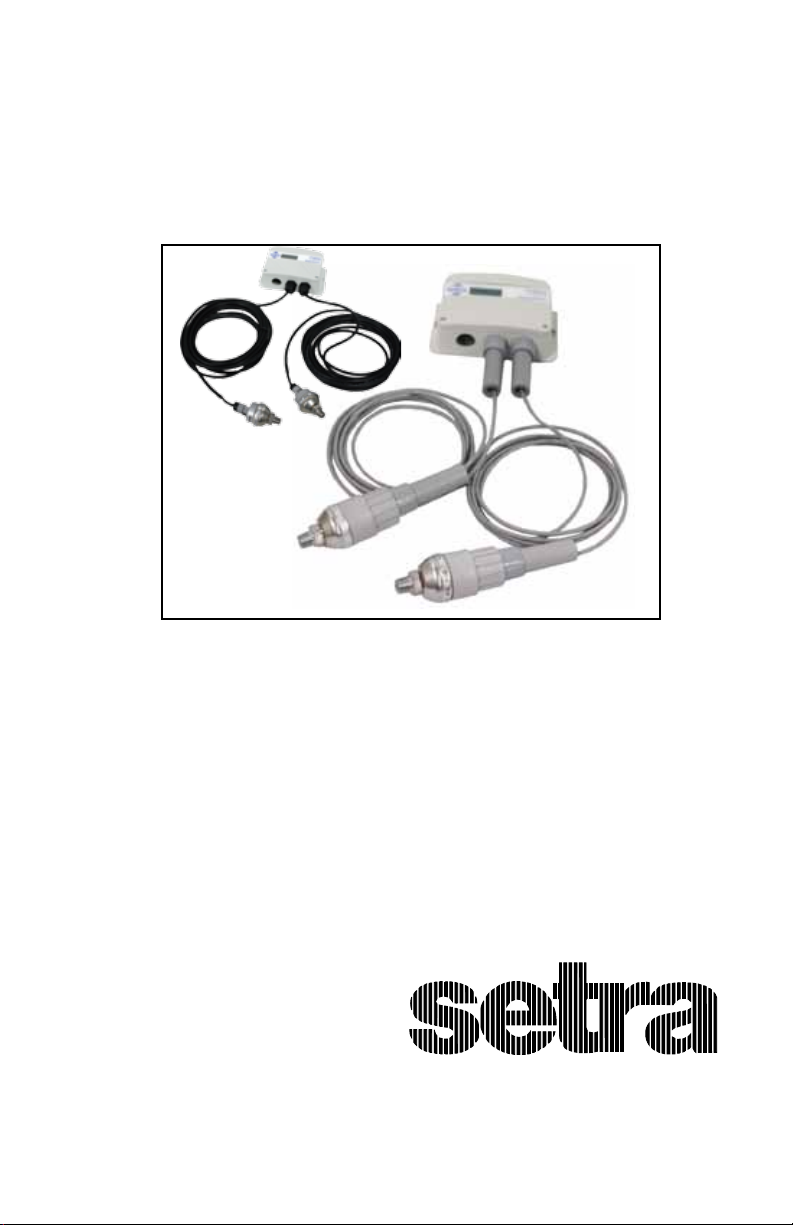
Model 231RS Multi-Sense®
Wet-to-Wet Pressure Transducer
with Remote Sensors
Installation and Operating Instructions
CE
RoHS
978-263-1400; 800-257-3872
www.setra.com; sales@setra.com
Page 2

Contents
1.0 GENERAL INFORMATION........................................................................3
2.0 MECHANICAL INSTALLATION ...............................................................3
2.1 Media compatibility .........................................................................3
2.2 Environment .......................................................................................3
2.3 Pressure Fittings ................................................................................4
2.4 Mounting .............................................................................................4
2.5 Installation Procedures ...................................................................4
3.0 ELECTRICAL INSTALLATION ..................................................................7
3.1 Electrical Termination
Wiring: 2-Wire , 4 to 20 mA and Remote Zero ..............................7
3.2 Electrical Termination
Wiring: 3-Wire, 0 to 5, 0 to 10, 1-5 VDC and Remote Zero ........8
3.3 Remote Sensors Installation...... ....................................................9
4.0 CONFIGURATION ................................................................................... 11
5.0 RETURNING PRODUCTS FOR REPAIR ........................................... 12
6.0 WARRANTY AND LIMITATION OF LIABILITY ..............................12
2
Page 3

Model 231RS Remote Sensors
Installation and Operating Instructions
Multi-Sense® Model 231RS Series
Wet-to-Wet Dierential Pressure Transducers
Your 231RS w/Conduit or 231RS w/Cable is shipped with the following:
Conduit Version
(231GRSX3MX)
Item Qty Item Qty
Housing 1 Housing 1
Pressure Transducers 2 Pressure Transducers
User Manual 1 Cable Assemblies
1.0 GENERAL INFORMATION
Every Model 231RS has been calibrated and tested before shipment to
guarantee performance of all pressure ranges.
The Model 231RS has eld selectable unidirectional and bidirectional pressure ranges, congurable 0 to 5 VDC, 0 to 10 VDC , and 1 to 5 VDC output, true
two-wire 4 to 20 mA output, and auto-zero capability. Each unit is factory calibrated to the highest pressure range. The range label on the side of the units
indicates the factory calibrated range. (Reminder: Your application’s high-
est line pressure should be ≤ to the highest pressure range of the 231RS
range code you selected when you purchased the 231RS, see Range Codes
in table below, [range codes also listed inside housing cover.).
Model 231RS pressure transducers sense wet-to-wet dierential pressure and
convert this dierence in pressure to a proportional high level analog output.
(231GRSX4MXXX)
User Manual
Cable Version
2
2
1
Your Multi-Sense® Model 231RS pressure transducer has been ordered in one
of the following versions:
Range Code Unidirectional Bidirectional
RS1 5, 10, 25, 50 psid ±5, ±10, ±25, ±50 psid
RS2 7.5, 15, 37.5, 75 psid ±7.5, ±15, ±37.5, ±75 psid
RS3 10, 20, 50, 100 psid ±10, ±20, ±50, ±100 psid
RS4 15, 30, 75, 150 psid ±15, ±30, ±75, ±150 psid
RS5 25, 50, 125, 250 psid ±25, ±50, ±125, ±250 psid
2.0 MECHANICAL INSTALLATION
2.1 Media Compatibility
Model 231RS transducers are designed to be used with any gas or liquid
compatible with 17-4 PH stainless steel. Never totally submerge the unit in
any liquid.
2.2 Environment
The operating temperature limits of the Model 231RS are as follows:
Compensated Temperature Range °F (°C) +32 to +130 (0 to +54)
Operating Temperature Range °F (°C) -4 to +185 (-20 to +85)
Storage Temperature Range °F (°C) -4 to +185 (-20 to +85)
3
Page 4
2.3 Pressure Fittings
Standard pipe ttings and installation procedures should be used.
Model 231RS have 1/4” -18 NPT male ttings. The high pressure port and low
pressure connections are located on the bottom of the unit, labeled “HI(+)”
and “LO(-)” respectively.
Important:
Each remote sensor is labeled “HIGH PRESSURE SENSOR” or “LOW PRESSURE
SENSOR”. Match up the high pressure sensor to the high pressure electrical terminals, and the low pressure sensor to the low pressure electrical
terminals. Otherwise, the performance may not meet the product linearity
specications.
Moisture Precautions
The Model 231RS is provided with a 0.875” DIA. conduit opening for electrical termination, intended for a 1/2” I.D. conduit connection. This opening
must be sealed according to standard industry practices in order to prevent
moisture ingress into the Model 231RS.
2.4 Mounting
The Model 231RS can be easily mounted using the two mounting tabs located
on the side of the unit.
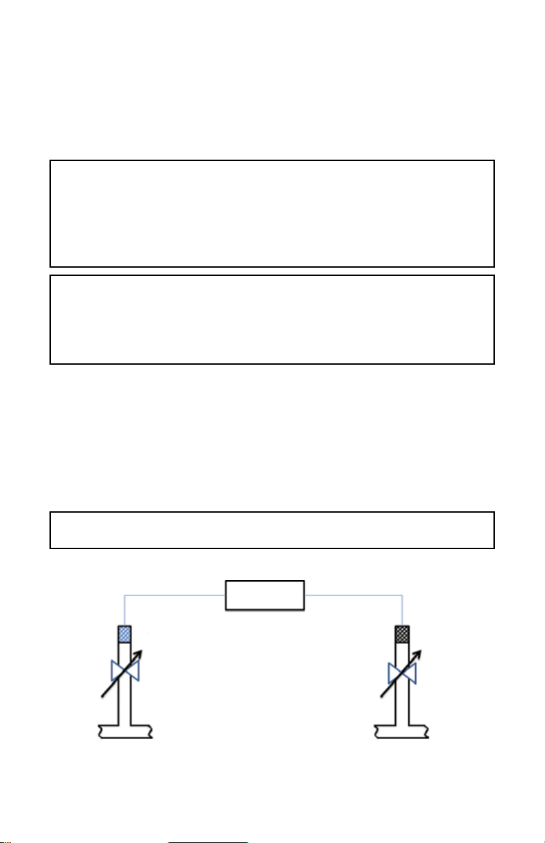
2.5 Installation Procedures
For dierential pressure measurements, it is recommended that the pressure
sensor be installed with a valve in each line.
.
Important: The maximum line pressure cannot exceed the maximum
dierential pressure of the sensor.
Valve A*
High
High Pressure
Remote Sensor
Valve A = High Side Valve
Valve B = Low Side Valve
Pipe
*Valves not included.
Model 231RS
Figure 1
4
Low Pressure
Remote Sensor
Pipe
Valve B*
Low
Page 5

Model 231RS (Conduit version, P/N: 231GRSX3MXXX) Outline Drawing.
6.0
152.4
R 0.1
2.5
0.35
8.8
1.98
50.3
5.56
141.2
2.0
50.8
Front View
Side View
4.0
102
1.56
39.6
Figure 2
2x
0.864
21.95
0.95
24.1
1.220
30.99
5.16
131.1
1.240
31.50
Bottom View
in.
mm
5
Page 6

Model 231RS (Cable version, P/N: 231GRSX4MXXX) Outline Drawing
6.0
152.4
5.56
141.2
R 0.1
2.5
0.35
8.8
2.0
50.8
1.98
50.3
4.0
102
4.87
123.6
Side View
5.08
129
1.56
39.6
1.22311.66
42.2
Front View
0.95
24.1
5.16
131.1
Bottom View
Figure 3
in.
mm
6
Page 7

3.0 ELECTRICAL INSTALLATION
To access the electrical connections, turn the screws on the top of the case
counter clockwise until the hinged cover can be ipped up. The screws are
captured and secured in the cover. Wiring is through the 1/2” conduit openings or PG ttings in the case of remote sensors with cable option. Both current and voltage outputs are reverse wiring protected.
Note: The Zero terminals, connected to digital output, provide a contact closure relay for automatic reset to zero
pressure by the monitoring system. CAUTION: ZERO input is for dry contact, do no apply voltage to ZERO
Terminals
3.1 Electrical Termination
Wiring: 2-Wire, 4 to 20 mA and Remote Zero
Model 231RS when congured as a current output transducer is a true
2-wire, 4-20 mA current output device and delivers rated current into any
external load of 0-250 ohms.
When congured as a 4-20 mA current output device the current ow is in
one direction only. PLEASE OBSERVE POLARITY.
We suggest that an electrical cable shield be connected to the system’s loop
circuit ground to improve electrical noise isolation.
Min. Supply Voltage: 15 + .02 x (Resistance of receiver plus line)
Max. Supply Voltage: 30 + .004 x (Resistance of receiver plus line)
The optional remote zero is a normally open relay wired between COM and
REMOTE ZERO terminals. In order to initiate ZERO function the relay contact
should be closed and sensor must be vented to atmosphere.
DC Power
Supply
Controller
(4-20 mA)
Relay
Current
+
+
Figure 4
7
Page 8

3.2 Electrical Termination
Wiring: 3-Wire, 0 to 5, 0 to 10, 1-5 VDC and Remote Zero
Model 231RS when congured for voltage output is a 3-wire circuit device
with three terminals available for wiring.
Model 231RS can operate from 15-30 VDC (18-30 VAC) nominal output power
supply.
Note: The Zero terminals, connected to digital output, provide a contact closure relay for automatic reset to zero
pressure by the monitoring system. CAUTION: ZERO input is for dry contact, do no apply voltage to ZERO
Terminals
The optional remote zero is a normally open relay wired between COM and
REMOTE ZERO terminals. In order to initiate ZERO function the relay contact
should be closed and sensors must be vented to atmosphere.
DC/AC
Power Supply
Controller
Voltage
Relay
+
+
Figure 5
8
Page 9

3.3 Remote Sensors Installation
Conduit Version (P/N: 231GRSX4MX)
For conduit version remote sensors, use the following instructions:
1 2 3 4 5
1. Install the remote sensor into the system plumbing (use 3/4” hex to tighten).
Important:
Each remote sensor is labeled “HIGH PRESSURE SENSOR” OR “LOW PRESSURE
SENSOR”, respectively. Match up the high pressure sensor to the high “HI (+)”
pressure electrical terminals, and the low “Lo (-)” pressure sensor to the low
pressure electrical terminals. Otherwise, the performance may not meet the
product linearity specications.
2. Install a 1/2” conduit tting into the remote sensor top cover and fasten the
retaining nut.
3. Feed wires from a exible conduit through the remote sensor top cover,
fasten the wires to terminals.
4. Screw on the top cover.
5. Fit conduit into conduit tting, and tighten conduit watertight strain relief.
To connect the wires from the remote sensor to the unit, remove the terminal
blocks from the circuit board and use the following chart:
Installation of the Model 231RS is now complete.
1/2 inch
Conduit
Opening
Terminal Block
(CN8 & CN11)
4
(GND)
3
+OUT
2
1
COM
+EXC
Conduit Adapter
Chart 1. Electrical wiring chart for
High & Low Pressure Sensors (Conduit version)
CAUTION:
Reverse excitation will permanently
damage unit. Please follow wiring
instructions carefully.
9
3.61
91.74
1.68
42.57
Figure 6
Dimensional Drawing
1.40
35.48
1.62
41.22
in.
mm
3/4” HEX
1/4” NPT
Page 10

Cable Version (P/N: 231GRSX4MXXX)
For conduit version remote sensors, use the following instructions:
1. Install the remote sensor into the system plumbing (use 3/4” hex to
tighten).
Important:
Each remote sensor is labeled “HIGH PRESSURE SENSOR” OR “LOW PRESSURE
SENSOR”, respectively. Match up the high pressure sensor to the high pressure
electrical terminals, and the low pressure sensor to the low pressure electrical
terminals. Otherwise, the performance may not meet the product linearity
specications.
2. Attach the cable provided to the 3-Pin Packard connector on the remote
sensor.
3. Feed the cable through the PG tting on the bottom of the unit and tighten
the tting.
4. Remove the terminal blocks from the circuit board and use the following
Terminal Block
(CN8 & CN11)
4
(Shield)
3
+OUT (White) C
2
COM (Black) A
1
+EXC (Red) B
Chart 2. Electrical wiring color chart for
3-Pin Packard
Connector
1.46
37.1
in.
mm
High & Low pressure sensors (Cable version)
0.325
8.3
3.0
76
1.62
41.22
Figure 7
Dimensional Drawing
Important: Prior to putting the unit into service, complete conguration setup
in Section 4. After conguration is complete, press the “Zero” button.
Installation of the Model 231RS is now complete.
10
Page 11

4.0 CONFIGURATION
Range Selection Auto Zero Button Electrical
Congurator
Electrical Connections
High Pressure
Electrical Terminals
Low Pressure
Electrical Terminals
Figure 8
Range Selection Switch: The unit is set to the highest range when calibrated
at the factory. To select the other ranges, slide the switch to the right. Important: Push “zero” button after installing the Model 231RS, and after
changing range.
Auto Zero Button: Press and hold the “ZERO” push-button for 2 seconds to
automatically reset zero or provide contact closure on “Remote Zero, see gure 4, pg. 7, and gure 5, pg. 8 . Sensors must be vented to atmosphere.
Electrical Output: The unit is set at the factory to 4-20 mA. To select another output, move the slide switch to the right. Push the “Zero” button after
changing the electrical output mode. Sensors must be vented to atmosphere.
Electrical Connections: Electrical termination for power supply, 3-wire voltage output and 2-wire true 4-20 mA current output, and remote zero wiring.
BAR/PSI: Jumper selectable engineering units in Bar ranges or PSI.
A. REV/NORM:
A.REV: Analog Reverse: When in reverse mode, the output increases when
the dierential pressure decreases and decreases as pressure increases.
NORM: When in Normal mode output increases as pressure increases and
decreases as pressure decreases.
SLOW/FAST: When Slow mode is selected, 5-second averaging is provided for
surge damping.
BI-DIR/UNI-DIR: Select UNI-Directional or BI-Directional mode.
Unidirectional mode measures from 0 to full scale dierential pressure.
Bidirectional mode measures pressure from minus 1/2 of full scale to plus 1/2
of full scale dierential pressure. Output will read 1/2 full scale when dierential pressure is zero.
SWAP/NORM: Jumper selectable Port Swap feature eliminates costly replumbing when incorrectly installed or replaced. Go from NORMAL to SWAP
and the jumper makes the “HI” Port “LO” and the “LO” port “HI.
High Pressure Electrical Terminals (HI): High pressure sensor termination.
Low Pressure Electrical Terminals (LO): Low pressure sensor termination.
11
Page 12

5.0 RETURNING PRODUCTS FOR REPAIR
Please contact a Setra application engineer (800-257-3872, 978-263-1400) before
returning unit for repair to review information relative to your application. Many times
only minor eld adjustments may be necessary. When returning a product to Setra, the
material should be carefully packaged, and shipped to :
Setra Systems, Inc.
159 Swanson Road
Boxborough, MA 01719-1304
Attn: Repair Department
To assure prompt handling, returned unit(s) must be accompanied by Setra’s Return
Order Form, completely lled out, found on Setra’s web site at :
http://www.setra.com/contactus/contact_us_service_calibration.htm
Notes: Please remove any pressure ttings and plumbing that you have installed and
enclose any required mating electrical connectors and wiring diagrams.
Allow approximately 3 weeks after receipt at Setra for the repair and return of the unit.
Non-warranty repairs will not be made without customer approval and a purchase
order to cover repair charges.
Calibration Services
Setra maintains a complete calibration facility that is traceable to the National Institute
of Standards & Technology (NIST). If you would like to recalibrate or recertify your
Setra pressure transducers or transmitters, please call our Repair Department at 800-
257-3872 (978-263-1400) for scheduling.
6.0 WARRANTY AND LIMITATION OF LIABILITY
SETRA warrants its products to be free from defects in materials and workmanship, subject to the following terms and conditions:
Without charge, SETRA will repair or replace products found to be defective in materials or workmanship within the warranty
period; provided that:
a) the product has not been subjected to abuse, neglect, accident, incorrect wiring not our own, improper installation or
servicing, or use in violation of instructions furnished by SETRA;
b) the product has not been repaired or altered by anyone except SETRA or its authorized service agencies;
c) the serial number or date code has not been removed, defaced, or otherwise changed; and
d) examination discloses, in the judgment of SETRA, the defect in materials or workmanship developed under normal
installation, use and service;
e) SETRA is notied in advance of and the product is returned to SETRA transportation prepaid.
Unless otherwise specied in a manual or warranty card, or agreed to in writing and signed by a SETRA ocer, SETRA pressure and
acceleration products shall be warranted for one year from date of sale.
The foregoing warranty is in lieu of all warranties, express, implied or statutory, including but not limited to, any implied warranty
of merchantability for a particular purpose.
SETRA’s liability for breach of warranty is limited to repair or replacement, or if the goods cannot be repaired or replaced, to a
refund of the purchase price. SETRA’s liabilit y for all other breaches is limited to a refund of the purchase price. In no instance
shall SETRA be liable for incidental or consequential damages arising from a breach of warranty, or from the use or installation of
its products.
No representative or person is authorized to give any warranty other than as set out above or to assume for SETRA any other
liability in connection with the sale of its products.
For all CE technical questions, contact Setra Systems, USA. EU customers may contact our EU representative, Hengstler GmbH,
Uhlandstr 49, Germany (Tel: +49-7424-890; Fax: +40-7424-89500.
159, Swanson Road, Boxborough, MA 01719
978-263-1400; 800-257-3872/www.setra.com; sales@setra.com
12
SS231RS RevB 09/08/11
 Loading...