

Page 1

OPERATING INSTRUCTIONS
MODEL 205-2 PRESSURE TRANSDUCER
FOUR-WIRE, VOLTAGE OUTPUT
GENERAL INFORMATION
Your Setra transducer has been carefully calibrated before shipment to you, and it should be handled with the
same care given any precision instrument. Pressure ranges and dimensions are reported on the specification
bulletin for the transducer.
INSTALLATION
Do not use in ambient conditions corrosive to polyvinyl chloride (cable) or stainless steel, submerged in liquids,
subject to spray or drip, or in a high vibration environment. The 205-2 Series is very slightly sensitive to
acceleration in the pressure fitting axis, less than 0.05 psi/g typical. Factory calibrated in the vertical position,
with pressure port downward, this position often minimizes damage from dripping of pressure system piping.
Installation of pressure fitting:
For very high pressure use of sealant such as Loctite hydraulic sealant is suggested.
For other pressure ranges, standard sealants such as Teflon tape generally are satisfactory.
For the most sensitive pressure ranges, excessive high torquing of a metal pressure fitting may cause a
slight zero shift which may be trimmed out using the zero adjustment. Use of plastic fittings often shows
no noticeable zero shift. The torquing effect does not appreciably affect linearity or sensitivity. Use the
wrench flats on the 205-2 when attaching to fittings.
Installation with FM approved Explosionproof/Weatherproof enclosure:
1. Conduit seals shall be placed no more than 18" from the enclosure.
2. Cables with gas/vapor tight continuous sheath, capable of transmitting gas or vapor through the
cable core, shall be sealed per National Electric Code (NEC) for Class 1, Division 1 (most current
revision).
3. Caution: Do Not open cover while circuits are live.
ATMOSPHERIC REFERENCE (Gage pressure transducers only)
Lower range units are subject to excessive thermal zero shift unless vented to atmosphere. The electrical cable
provides this equalization vent.
ELECTRICAL CONNECTIONS:
CABLE LEAD FUNCTION
Red positive excitation
Green positive output
White negative output
Black negative excitation
Shield case
ELECTRICAL
The electrical circuit is equivalent to a 4 terminal network, which can be grounded at only one point, either at the
negative excitation or the negative output lead, but must not be commoned or grounded at more than one point.
The negative output lead is approximately 1.66 VDC above the negative excitation lead. The positive output
lead is at this same 1.66 VDC common mode voltage plus the output signal from applied pressure (thus goes
from approximately 1.66 VDC up to 6.66 VDC above the negative excitation).
The pressure transducer must be operated with the case connected either to the negative excitation terminal or
to the negative output terminal. Failure to do this may result in damage to or
unsatisfactory operation of the unit. This connection may be made by connecting
the shield to white or shield to black leads. Best shielding against noise will be
obtained by connecting the shield and negative excitation (black) leads.
Linearity Adjust
(Do Not Touch)
Sensitivity Adjust
Circuit is reversed voltage protected for at least 5 minutes. Internal
transient suppression network is provided for short duration transients to
150 volts.
In some instances, use of long cables (several hundred feet
Zero Adjust
length) may introduce enough cable capacitance into the
Page 2
output circuit to cause output oscillation. If encountered, this oscillation may be eliminated by connecting a 100
ohm resistor (1/8 watt or larger) in series in each of the output leads at the end of the 2 foot transducer cable.
These series resistors, of course, add to the output resistance.
CAUTION: Excitation power, or voltage in excess of 15 VDC, inadvertently applied to the output leads may
damage the electrical circuit. Care must be taken when installing this transducer that the excitation voltage is not
applied to the output leads by mistake. Shielding or other precaution should be provided to assure that transient
voltages in excess of 15 VDC are not applied to the output leads.
ADJUSTMENTS (with cover removed)
CAUTION: TURN OFF EXCITATION POWER DURING COVER REMOVAL OR REPLACEMENT.
ZERO PRESSURE OUTPUT
Unit factory adjusted to within ± 50 mV. Can be adjusted by the air trim capacitor as shown in the diagram. Any
adjustments will begin to change sensitivity.
SENSITIVITY
Can be adjusted by potentiometer as shown on diagram. Unit factory adjusted to order specifications.
OTHER ADJUSTMENT
Adjusted at factory. Touching any adjustments other than zero output or sensitivity may necessitate recalibration.
Do not touch.
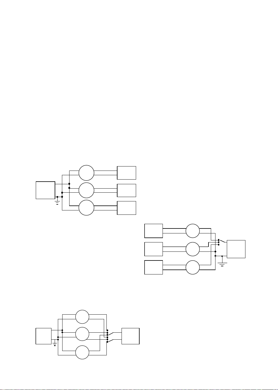
INSTALLATION INSTRUCTIONS FOR MULTIPLE HOOK UP OF A 4-WIRE SETRA PRESSURE TRANSDUCER
+
-
+
-
+
-
POWER
SUPPLY
GROUND
+EX
-EX
+EX
+
-EX
-
+EX
-EX
+out
PT
-out
+out
PT
-out
+out
PT
-out
Option#2
Uses a separate, isolated power supply for each
pressure transducer's excitation and a single,
ground referenced readout or "single-ended input"
to a data acquisition system for all of the outputs.
PS - Power Supply (Nominal 24 VDC)
PT - Pressure Transducer (4 Wire Circuit)
DVM/DAS - Digital Volt Meter or Data Acquisition System
+out
PT
-out
+out
PT
-out
+out
PT
-out
POWER
SUPPLY
+EX
-EX
+EX
+
-
-EX
+EX
-EX
DVM/DAS
DVM/DAS
DVM/DAS
+
DVM/DAS
-
Option #1
Uses a single, ground referenced power supply for
excitation and separate, isolated, (not ground
referenced), readout or "differential input" to a data
acquisition system for each pressure transducer
output.
POWER
SUPPLY
POWER
SUPPLY
POWER
SUPPLY
+
+EX
-
-EX
+
+EX
-
-EX
+
+EX
-
-EX
+out
PT
-out
+out
PT
-out
+
DVM/DAS
-
+out
PT
-out
Option #3
Uses a single, ground referenced power supply
for excitation and either a single, isolated readout
with a bipolar switch that "breaks before makes"
both the + output and - output of each pressure
transducer, or a single data acquisition system with
a multiplexer (MUX).
NOTE: The shield is internally commoned to the
case and pressure port of the transducer. When the
shield is connected to ground, the case and pressure
port of the transducer will also be commoned to that
ground.
Page 3

CALIBRATION SERVICES
Setra maintains a complete calibration facility that is traceable to the National Institute of Standards & Technology
(NIST). If you would like to recalibrate or recertify your Setra pressure transducers please call our Repair
Department at 1-800-257-3872 (978-263-1400) for scheduling, cost and turnaround estimates.
RETURNING PRODUCTS FOR REPAIR
Please contact Setra (1-800-257-3872 or 978-263-1400) before returning unit for repair to review information relative
to your application. Many times, only minor field adjustments may be necessary.
When returning a product to Setra, the material should be carefully packaged and shipped prepaid to:
Setra Systems, Inc.
159 Swanson Road
Boxborough, MA 01719
Attn: Repair Department
To assure prompt handling, please supply the following information and include it inside the package of returned
material:
1. Name and phone number of person to contact.
2. Shipping and billing instructions.
3. Full description of the malfunction.
4. Identify any hazardous material used with product.
Notes: Please remove any pressure fittings and plumbing that you have installed and enclose any required
mating electrical connectors and wiring diagrams.
Allow approximately 3 weeks after receipt at Setra for the repair and return of the unit.
Non-warranty repairs will not be made without customer approval and a purchase order to cover repair charges.
LIMITED WARRANTY AND LIMITATION OF LIABILITY
SETRA warrants its products to be free from defects in materials and workmanship, subject to the following terms and
conditions: Without charge, SETRA will repair or replace products found to be defective in materials or workmanship
within the warranty period; provided that:
a) the product has not been subjected to abuse, neglect, accident, incorrect wiring not our own, improper
installation or servicing, or use in violation of instructions furnished by SETRA;
b) the product has not been repaired or altered by anyone except SETRA or its authorized service agencies;
c) the serial number or date code has not been removed, defaced, or otherwise changed; and
d) examination discloses, in the judgment of SETRA, the defect in materials or workmanship developed under
normal installation, use and service;
e) SETRA is notified in advance of and the product is returned to SETRA transportation prepaid.
Unless otherwise specified in a manual or warranty card, or agreed to in writing and signed by a SETRA officer,
SETRA pressure and acceleration products shall be warranted for one year from date of sale.
The foregoing warranty is in lieu of all warranties, express, implied or statutory, including but not limited to, any implied
warranty of merchantability for a particular purpose.
SETRA’s liability for breach of warranty is limited to repair or replacement, or if the goods cannot be repaired or
replaced, to a refund of the purchase price. SETRA’s liability for all other breaches is limited to a refund of the
purchase price. In no instance shall SETRA be liable for incidental or consequential damages arising from a breach of
warranty, or from the use or installation of its products.
No representative or person is authorized to give any warranty other than as set out above or to assume for SETRA
any other liability in connection with the sale of its products.
Page 4

Setra Systems, Inc.
Product Line Summary
Pressure Transducers/Transmitters/Gages & Accelerometers
Model
204/204D
205-2
206/207
209
212
212FT
280E
280E-XP
FM
Approved
270
C290
228-1
239
264
370
470
Accelerometer
141
Applications
Hazardous Environments
R & D Laboratories
Vacuum Systems
High Accuracy General Purpose
R & D Test & Measurement
Vacuum Systems
Dynamometers
Engine Test Cells
Equipment Automation
Compressor Control
Chillers
Paper Converting Machines
Hydraulics & Pneumatics
Off Road Equipment
Hydraulic Equipment
Compressor Control
HVAC/R Equipment
Industrial Engines
Specialty Gas Handling
Semiconductor Process
Gas Bottle Filling Equipment
Pharmaceutical & Biotechnology
Process
High Press. Liquid Chromatography
Process Instrument Signals
Explosionproof/weatherproof
Natural Gas Lines
Chemical Processing
Off-Shore Drilling
Weather Data Systems
Laser Interferometers
Altimeter Setting Indicators
Transfer Pressure Standard
Sanitary Pressure Lines
Food & Beverage Processing
Tank Level Measurement
Pharmaceutical Processing
Sanitary Filtration Systems
Process Control
Filter Condition Monitoring
Refrigeration Equipment
Pump Speed Control
HVAC Equipment
HVAC Control
Leak Detection
Environmental Testing
R & D Scientific
Fume Hood Control
HVAC and VAV Control
Energy Management Systems
Clean Room Control
Medical Instrumentation
Filter Condition Monitoring
Altimeter Certification
Pressure Transfer Standard
Laser Interferometers
Min/Max Tracking
Hi/Lo Alarming
Automatic Weather Systems
High Accuracy Altimeter
Weather Data Buoy
Hydrological (SDI-12) option
Transportation Equipment
Position Sensing
Robotics
Shock & Vibration Testing
Type of
Pressure
Measurement
Absolute
Gage
Vacuum
Absolute
Gage
Gage
Gage
Gage
Compound
Absolute (212)
Gage
Absolute
Compound
P/I
Barometric
Gage
Absolute
Gage
Differential
(can be wet both sides)
Differential
Very low
Differential
Absolute
Barometric
G Ranges
(Full Scale Ranges ±G)
Pressure
Ranges
25 to 5000 psia
25 to 10000 psig
0-14.7 psiv
25 to 5000 psia
25 to 5000 psig
25 to 5000 psig
M206 Avail. in
1.6 to 400 bar
50 to 5000 psig
Common bar
ranges
-14.7 - 3000 psig
100 - 3000 psig
100 - 3000 psia
15 - 10000 psig
25 - 5000 psia
-14.7 to 100 psig
3 - 15 psig
600-1100 mbars
800-1100 mbars
10 to 100 psia
5 to 100 psig
1 to 1000 psig
1 to 100 psid
±0.5 to ±50 psid
0.5" to 30" WC
±0.25" to ±15" WC
5 to 10 psid
±2.5 to ±5 psid
0.1" to 25" WC
±0.1" to ±5" WC
(Pa, mbar &
mmWC ranges
available
600-1100 mbar
800-1100 mbar
0 to 10, 20, 50, 100
psia
±2,±4,±8,±15,±30,
±60,±150,±600g
Response:
DC to 3000 Hz
Accuracy
(RSS Method)
± % FS
0.11
.073 (opt.)
0.11
0.13
0.25
0.14 (212FT)
0.22 (212)
0.11
0.05
Option
.03
0.20
Low Ranges
0.15
High Ranges
0.21
0.14
Option
.073
1.00
Option
0.25 & 0.4
±0.02
1.00
Thermal
Effect
± % FS/100°F
(± % FS/100°C)
0.4 (.72) max Zero
0.3 (.54) max Span
0.02 (3.6) max Zero
1.5 (2.7) max Span
1.0 (1.8) max Zero
1.5 (2.7) max Span
2.0 (3.6) max Zero
1.5 (2.7) max Span
1.5 (2.7) max Zero
1.0 (1.8) max Span
0.75 (1.4) Zero
1.5 (2.7)Span
(Typ.)
2.0 (3.6) max Zero
2.0 (3.6) max Span
0.1 (.18) max Zero
(0.2 (.36) Baro.)
0.1 (.18) max Span
2.0 (3.6) max Zero
2.0 (3.6) max Span
2.0 (3.6) max Zero
2.0 (3.6) max Span
1.0 (1.8) max Zero
1.0 (1.8) max Span
3.3 (5.9)
Zero & Span
combined
0.2 max Zero
0.1 max Span
2.0 (3.6) max Zero
2.0 (3.6) Max Span
Media
Compatability
Gas or liquid
compatible
with stainless
Gas or liquid
compatible
with stainless
Gas or liquid
compatible
with stainless
Gas or liquid
compatible
with stainless
Corrosive liquids
or gases
(Ultra-High Purity
Gas & Liquid
Compatible)
Gas or liquid
compatible
with stainless
Wet or Dry
Gas or liquid
compatible
with stainless
Gas or liquid
compatible with
stainless steel
(both pressure &
reference sides)
High Pressure Port
Gas or liquid
compatible with SS,
aluminum & Buna-N
Low Pressure Port
Clean dry air or inert
Inert gases
Inert gases
steel
steel
steel
steel
steel
steel
gas
N/A
Air
Air
or
Air
or
Output
204
0-5 VDC
C-204
4-20 mA
0-5 VDC
206/207
0.1-5.1 VDC
C-206/C-207
4-20 mA
1.0-6.0 VDC
0.2-5.2 VDC
0.5-4.5 VDC
1.0-5.0 VDC
4-20 mA
212/212FT
0.2-5.2 VDC
C212/C212FT
4-20 mA
280E
0-5 VDC
C280E
4-20 mA
0-5 VDC
4-20 mA
228-1
0-5 VDC
Bidirectional
±2.5 VDC
C228-1
4-20 mA
239
0-5 VDC
Bidirectional
±2.5 VDC
C-239
4-20 mA
264
0-5 VDC
C-264
4-20 mA
RS-232
141A
±500mv (nom.)
141B
±1000mv (nom.)
159 Swanson Road, Boxborough, MA 01719/1-800-257-3872, (978)263-1400
SSO251REV B 10/23/97
 Loading...