

Page 1

Operating Instructions
Model 204 and 239 Pressure Transducers
Pressure Transducers (0 to 5 VDC output)
Model 204 Gauge, Absolute, and Vacuum Pressure
Model 204D Wet/Dry Differential Pressure
Model 239 Differential Pressure
General Information and Installation ..........................................................................................1
Electrical Information for Standard 24 VDC
Excitation Pressure Transducers (nominal) ..............................................................................3
Electrical Information for Optional ±15 VDC (±24 VDC)
Excitation Pressure Transducers (Option #: 621 and 622) ....................................................4
Adjustments for Pressure Transducers and Transducers
Zero and Sensitivity .......................................................................................................................5
Remote Control Instructions for Pressure Transducers ........................................................6
Installation Instructions for Multiple Hook-Up of 4-Wire
Pressure Transducers (24 VDC Excitation Units Only) ...........................................................7
Returning Products for Repair .....................................................................................................8
Calibration Services .......................................................................................................................8
EMC Certication ............................................................................................................................8
Limited Warranty ............................................................................................................................8
General Information and Installation
Your Setra transducer has been carefully calibrated before shipment to you, and it should be handled
with the same care given any precision instrument. Pressure range and dimensions are reported on
the applicable specications bulletin.
Ambient Conditions
Do not submerge in liquids, use in ambient conditions corrosive to anodized aluminum, subject to
spray or dripping, or use in a high vibration environment. The transducer is very slightly sensitive to
acceleration in the pressure tting axis (see applicable specications bulletin for acceleration response
specications). Installation is recommended in the vertical position, with the pressure port downward.
This position minimizes damage from drippage of pressure system piping.
Page 2

Installation of Pressure Fittings
Your transducer is designed for most accurate operation when subjected to pressures within the
designated pressure range. Refer to the catalog bulletin specications for proof pressure limits.
Subjection to excessive pressure voids the warranty. DO NOT OVERPRESSURE.
Standard sealants such as Teflon pipe tape generally are satisfactory. For the most sensitive pressure
ranges, excessive high torquing of a metal pressure tting may cause slight zero shift which may be
trimmed out using the zero adjustment. Use of a plastic tting often shows no noticeable zero shift.
The torquing effect does not appreciably affect linearity or sensitivity. The wrench flat on the 204 and
239 series should be used when installing the positive pressure tting.
A. Positive Pressure Fitting and Media Compatibility
Model 204, 204D: 1/4”-18 NPT internal tting
For use with gases or liquids compatible with 17-4 PH stainless steel.
(316 stainless steel optional)
Model 239: 1/8”-27 NPT internal tting
For use with gases compatible with stainless steel, hard anodized
6061 aluminum, Buna N “O” ring. (stainless steel in place of aluminum
optional)
B. Reference Pressure Fitting and Media Compatibility (Differential pressure measurements only.)
Model 204D: 1/8”-27 NPT internal tting
For use with clean dry air, non- corrosive or non-conductive gases.
Maximum line pressure 1000 PSIG.
204D, 239, C239
High
Low
Model 239: 1/8”-27 NPT internal tting
For use with non-corrosive, non-condensing clean dry air or other
gases. Maximum line pressure 250 PSIG.
NOTES:
(1) Differential pressure Models can be used to measure gauge pressure by leaving the reference port
open to atmosphere.
(2) Line Pressure refers to pressure applied to both high and low sides of the sensing device
simultaneously. Refer to the product data sheet to determine maximum differential pressure and
overpressure limits.
2
Page 3
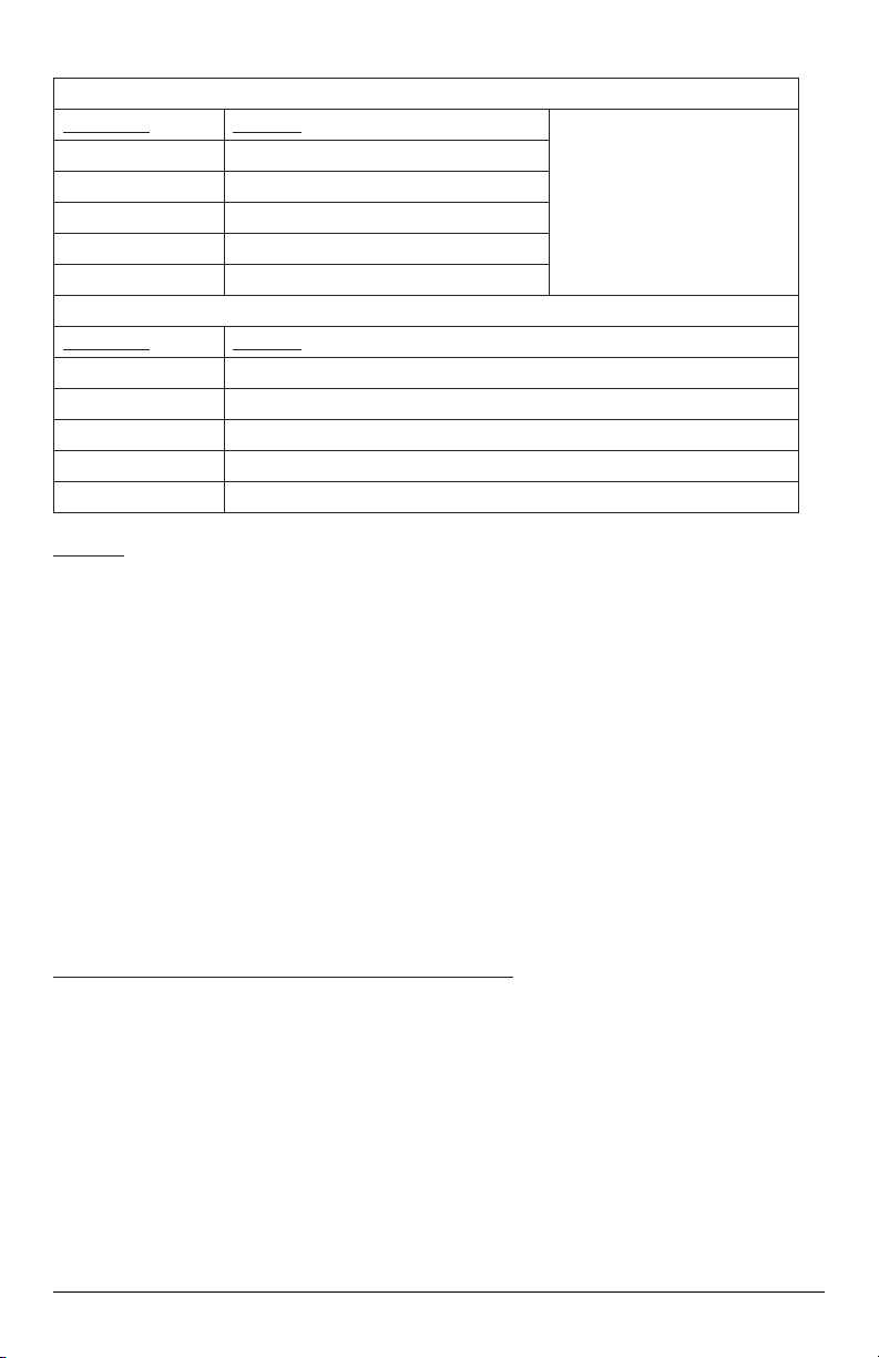
Electrical Information for Standard 24 VDC Excitation Pressure Transducers (nominal)
Connections (Model 204, 239; Electrical Termination Y1, Y4, Y4, Y6)
Cable Lead Function Note: Other leads in the
White Positive Excitation
Yellow Positive Output
Brown Negative Output
Black Negative Excitation
Shield Case
Connections (Model 204, 239; Electrical Termination 02, 10, 25)
Cable Lead Function
Red Positive Excitation
Black Negative Excitation
White Negative Output
Green Positive Output
Shield Case
Electrical
The electrical circuit is equivalent to a 4 terminal network, which means negative excitation lead shall
not be connected to negative signal output lead.
The pressure transducer must be operated with the case connected to earth ground to meet EMC
requirement. Best performance will be achieved by connecting the shield and negative excitation lead
if it is feasible and allowed.
cable are not used with the
standard pressure transducer
unless the transducer has
been wired for Remote
Control (see Remote Control
Instructions)
The circuit has internal protection:
• Reversed excitation voltage for at least 5 minutes.
• Short-circuit or signal output leads.
• Short duration power line transients up to 150 volts.
NOTE ON LONG CABLE USE:
In some instances, use of long cables (several hundred feet length) may introduce enough cable
capacitance into the circuit to cause output oscillations. If encountered, this oscillation may be
eliminated by connecting a 100 ohm resistor (1/8th watt or larger) in series to each of the output leads
at the end of the 2 foot transducer cable. These series resistors, of course, add to the output resistance.
Atmospheric Reference (Gauge Pressure Transducers only)
Lower range units are subject to excessive thermal zero shift unless vented to atmosphere. The electrical
cable provides this equalization vent. Do not seal the electrical cable when installing
3
Page 4

Electrical Information for Optional ±15 VDC (Option 622) and ±24VDC (Option 621)
Excitation Pressure Transducers
NOTE:
Any gures in parentheses ( ) pertain to the ±24 VDC excitation units only.
Connections (Model 204, 239; Electrical Termination Y1, Y4, Y4, Y6)
Cable Lead Function Note: Other leads in the cable are
White +15 (+24) Positive Excitation
Black
(Power Supply)
Violet -15 (-24) Negative Excitation
Yellow Positive Output
Brown Negative Output
Shield Case
Electrical
Electrical Option 622 permits operation from a ±15 VDC and electrical Option 621 permits operation
from a ±24 VDC supply (common return grounded), and provides you with the negative signal output
lead also at the common ground potential. Thus many transducers can be operated from one power
supply into single-ended loads. Circuit is reversed voltage protected for at least 5 minutes. Internal
transient suppression network is provided for short duration transients to 150 volts.
Grounding
For general usage and best results (lowest noise) grounding of the shield/case to the black lead is
recommended.
Ground
not used for electrical Option 621
and 622 unless the transducer has
been wired for Remote Control (see
Remote Instructions)
Power Supply Advice
This transducer has been designed to operate from a dual ±15 VDC (±24 VDC ) source. Stated another
way, the supply is a 30V (48V) center tapped supply. The ±15 V (±24 V) is 15 V (24 V) above the
common power return lead, and the - 15 V (- 24 V) is 15 V (24 V) below the common power return lead.
All three power leads must be connected. The transducer will not function if just the +15 V (+24 V) and
-15 V (-24 V) leads are connected to the power source. To avoid circuit damage due to excessive
voltage, the positive supply voltage should be held within the range of +15 V to +20 V (+22 V to +30
V), and the negative supply voltage should be held within the range of -10 V to -20 V (-10 V to -24 V).
NOTE ON LONG CABLE USE:
In some instances, use of long cables (several hundred feet length) may introduce enough cable
capacitance into the circuit to cause output oscillations. If encountered, this oscillation may be
eliminated by connecting a 100 ohm resistor (1/8th watt or larger) in series to each of the output leads
at the end of the 2 foot transducer cable. These series resistors, of course, add to the output resistance.
4
Page 5

Adjustments for Zero and Sensitivity
IC IC
Temperature
Compensation
DO NOT TOUCH
Zero Adjust
Sensitivity Adjust
Linearity Adjust
DO NOT TOUCH
Adjustments for Voltage Output Pressure Transducers (cover must be removed)
CAUTION:
TURN OFF EXCITATION POWER DURING COVER REMOVAL OR REPLACEMENT
Zero Pressure Output
Can be adjusted to zero by potentiometer as shown in diagram. Unit factory - adjusted to zero output
(±10 mV for Model 204 and ±20 mV for Model 239).
Sensitivity (span)
Can be adjusted by potentiometer as shown on outline diagram. Unit factory - adjusted to order
specications.
Linearity
DO NOT TOUCH - Factory adjusted for best linearity. Touching any adjustments other than zero
output or sensitivity may necessitate recalibration.
NOTE:
Sensitivity (span) adjustment is not recommended unless a primary pressure standard (dead weight
tester, etc.) is available for use as a reference.
5
Page 6

Remote Control Instructions for Pressure Transducers
Yellow
Blue
Violet
*Red
(M239 w/Option 621/622
and 642)
*Brown
(M204 w/option 621/622 and 642)
10K
Cable leads indicated below are connected into the transducer circuitry on this transducer as ordered.
Connection of the remote control leads extends the internal zero and sensitivity adjustments. The
Transducer was factory calibrated with the remote control wiring disconnected.
CAUTION:
The remote control leads directly access active circuit elements. Inadvertent short-circuiting to each
other, to ground, or other mis-wiring may cause immediate circuit damage. Keep remote control wiring
either free of other contact or else keep the leads properly wired as shown below.
Note: All resistance elements are 0.1 watt or greater. All remote circuits have voltages less than 10
volts and currents less than 1 mA.
Remote Zero Adjustment (standard)
The transducer has been preset with the regular internal
zero adjustment potentiometer. If remote
zero control is desired, connect the orange, green and
black leads as shown with external resistors
and potentiometers.
Remote Sensitivity Adjustment (optional)
The transducer has been preset with the regular internal
sensitivity adjustment potentiometer. If
remote sensitivity control is desired (Option 642), connect
the yellow, blue and violet* leads and
adjustable resistance as shown.
*For Models 239 and 204 w/options 621/622 and 642,
replace violet lead as shown.
Fixed:
Adjustable:
6
Remote Calibration Signal (optional)
Two types of calibration signal zero offset are offered:
Fixed calibration signal closing red to black leads.
Adjustable calibration signal, on closing circuit with an
adjustable resistance between red and black
leads. Suggest use of a 100K potentiometer.
Page 7

Installation Instructions for Multiple Hook-Up of 4-Wire Pressure Transducers (24 VDC Units Only)
PS - Power Supply (nominal 24 VDC)
PT - Pressure Transducer (4-Wire Circuit)
DVM/DAS - Digital Voltmeter or Data Acquisition System
Option #1
Uses a single, ground referenced power supply for excitation and separate, isolated differential
input (not ground referenced) readout or data acquisition system for each pressure transducer
output.
Option #2
Uses a separate, isolated power supply for each pressure transducer’s excitation and a single,
ground reference (single ended input) readout or data acquisition system for all of the outputs
Option #3
Uses a single, ground referenced power supply for excitation and either a single, isolated readout
with a bipolar switch that “breaks before makes” both the + output and the - output of each pressure
transducer, or a single data acquisition system with a multiplexer (MUX).
NOTE:
The shield is internally commoned to the case and pressure port of the transducer. When the shield is
connected to ground, the case and pressure port of the transducer will also be commoned to that ground.
7
 Loading...