

Page 1

WCPT-3 and WCPT-4
Service and Installation Manual
Please read this manual completely before attempting to install or operate this equipment!
Notify carrier of damage! Inspect all components immediately. See page 1.
Drop-in Display Cases
Effective Date: 2011
IMPORTANT INFORMATION
READ BEFORE USE
Page 2
1
Page 3

Project: ___________
2
Item No.: ___________
Quantity: ___________
DROP-IN SERVING EQUIPMENT
DISPLAY CASE
Refrigerated,
Pass-Through
Self-Contained
WCPT-3
WCPT-4
SPECIFICATIONS
TOP: Constructed of 18 gauge, type 304 stainless steel, die stamped
with a raised perimeter bead. The top is solid, full-length, to support
the refrigerated display case. There shall be a solid vinyl gasket
under the beaded edge to form a seal to the counter top, thus preventing seepage or marring of the counter top.
DISPLAY CASE: Double wall constructed of type 304 stainless steel
- 20 gauge, both interior and exterior, and filled with 2" of foamed-inplace polyurethane insulation. Customer's side and operator's side
are provided with a set of two (2) sliding, self-closing, thermo-pane,
insulated glass doors. The doors are removable for ease of cleaning.
The display case is provided with two (2) plastic coated wire shelves,
adjustable on 1" increments, and two (2) sets of fluorescent light fixtures mounted behind plastic guards which are recessed into the
side panels. The light fixtures are provided with a separate on/off
switch. An internal thermometer is provided.
REFRIGERATION SYSTEM: The compressor housing shall be fabricated from 14 gauge galvanized and bolted to the base of the unit. A
fully self-contained condensing unit is provided with a hermetically
sealed compressor and a thermostat control. The system is also provided with a forced air evaporator, for even temperature throughout
the display case, which drains into a condensate evaporator, prewired in the unit. The system is fully charged with CFC free refrigerant and ready to operate.
NOTE: Proper ventilation must be provided in counter.
ELECTRICAL: The unit will be wired for 15 amps., 120 volt, single
phase operation with an on/off thermostat switch and pilot light. A 6'
long, 3-wire cord and plug (NEMA 5-15P) will be provided.
STANDARD FEATURES
!
Large, lighted display area with adjustable shelves - it’s the
ideal merchandiser
!
Sliding glass doors on customer’s and operator’s side,
making loading and self-service move quickly
!
Forced air evaporator blower system for maximum efficiency
in cooling
! Factory applied gasket - makes installation a snap and seals
units to the counter top, thus eliminating seepage
!
1-Year Parts & Labor Warranty
!
UL Recognized
ACCESSORIES
!
5YW - 5-Year Compressor Warranty
! Door Locking Device (2 required)
! Extra Shelf
! Plastic Laminate Trim
! Sliding Doors with Reflective Tempered Vision Panel (bronze
or gray)
! Solid (1) piece Tempered Reflective Vision Panel (bronze or
gray)
! Solid Stainless Steel Back
!
RS - Remote on/off switch for counter mounting
! RDVE - Rear Drain Valve Extension
! * 220 Volt - 50 Cycle Compressor
Specifications subject to change without notice.
* Units with these accessories are not currently UL listed.
DI-39
Page 4
REFRIGERATED PASS THROUGH DISPLAY CASE
3
WCPT SERIES
--------------------------------------------------------------------------------------------------------------------------------------------------------------------
--------------------------------------------------------------------------------------------------------------------------------------------------------------------
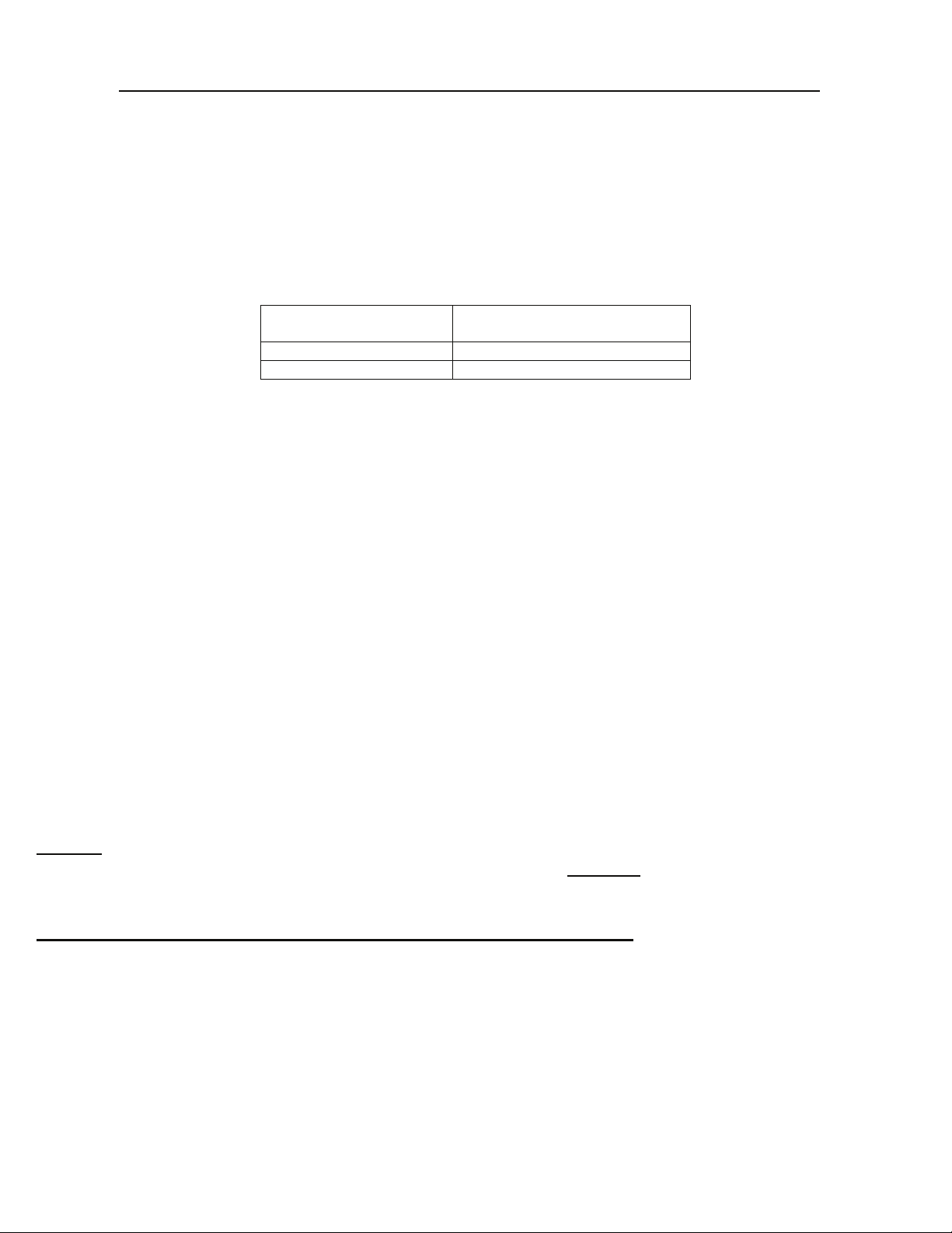
INSTALLATION
Provide the correct counter cut-out opening (see chart below) and drop unit in. The vinyl gasket assures complete
seating. A non-toxic silicone sealer may be used between the gasket and counter top (not required).
MODEL
WCPT-3 22 1/4" X 41 3/4"
WCPT-4 22 1/4" X 55 1/2"
The unit should be level for draining purposes. When installing unit in counter, it is recommended that the operator
side of the counter be completely open for air circulation. When this is not possible, such as in an island counter, it
is recommended that two grill openings are provided approximately 18” x 18” of free air for intake and exhaust at
the opposite ends of counter. Also the counter must have an opening of approximately 24” x 14” to access the
compressor for maintenance. Then the refrigeration components can be reached by removing six (6) screws from
control and rear panels.
The unit is supplied with a power cord and NEMA plug. Refer to data plate on compressor housing for the
amperage and voltage information. Use a licensed electrician when installing power source.
For cleaning and maintenance of inside top evaporator coil a qualified refrigeration technician is recommended.
--------------------------------------------------------------------------------------------------------------------------------------------------------------------
--------------------------------------------------------------------------------------------------------------------------------------------------------------------
CUT-OUT
REQUIRED
OPERATION
The unit is ready to be operated as soon as it is plugged in and switched on. The unit has been pre-tested for proper
operation from 35 to 40 degrees.
-------------------------------------------------------------------------------------------------------------------------------------------
---------------------------------------------------------------------------------------------------------------------------------------
MAINTENANCE
NEVER CLEAN THE UNIT WITH A CHLORIDE BASED PRODUCT. CHLORIDES OR IMPROPER
CLEANING COULD SCAR, MARK AND/OR CORRODE METAL. DO NOT USE STEEL WOOL OR
ABRASIVE PRODUCTS. TO CLEAN USE SOAPY WARM WATER, RINSE THOROUGHLY TO REMOVE
ALL RESIDUES. CLEAN CONDENSER COIL REGULARLY.
FAILURE TO MEET THESE CONDITIONS WILL VOID WARRANTY.
Page 5

SLIDING DOOR MAINTENANCE
4
ATLAS WCPT DISPLA Y CASES ARE PROVIDED WITH
EASY REMOVABLE SLIDING DOORS. CLEANING OF
THE DOOR GASKETS AND DOOR FRAME TRACKS
WITH MILD SOAP AND WATER WILL INSURE
SLIDING DOOR ASSEMBLY TO OPERATE
PROPERLY.
CAUTION - NEVER USE FULL STRENGTH CLEANING PRODUCTS ON GASKETS AS THIS WILL CAUSE
THEM TO BECOME BRITTLE AND CRACK VOIDING YOUR WARRANTIES.
SLIDING DOOR REMOVAL AND REINSTALL
SLIDING DOOR REMOVAL
OPEN THE OUTSIDE DOOR HALF WAY. FIRMLY PLACE FINGER ON DOOR RETURN SPRING OPERATOR AT THE TOP
AND MOVE THE DOOR SLIGHTLY CLEARING THE OPERATOR FROM THE NOTCH. GRASP BOTH SIDES OF THE DOOR
LIFTING UP HIGHER. TILT THE DOOR BOTTOM OUT OF THE BOTTOM TRACK, LOWER DOOR AND AWAY GENTLY TO
ALLOWING THE RETURN SPRING TO CLOSE.
REPEAT THE INSIDE DOOR WITH THE SAME PROCEDURE.
SLIDING DOOR REINSTALL
FIRST INSTALL THE DOOR MARKED INSIDE, GRASP FIRMLY ON BOTH SIDES LIFTING THE DOOR NOTCH INTO THE
DOOR RETURN SPRING OPERATOR AT THE TOP TRACK AND LIFT UPWARDS UNTIL THE DOOR STOPS AND SET THE
BOTTOM OF THE DOOR INTO THE BOTTOM TRACK. REPEAT PROCEDURE FOR THE OUTSIDE DOOR.
Customer Service | Telephone (800).762.7545 | Fax (305).623.0475 | Online www.atlasfoodserv.com
Page 6

SHELF INSTALLATION
5
ATLAS DISPLAY CASES COME STANDARD WITH TWO COATED WIRE SHELVES THAT ARE ADJUSTABLE IN 1/2"
INCREMENTS.
*ACCESSORY SHELVING MAY BE PROVIDED UPON REQUEST BRINGING THE TOTAL LIMIT TO THREE SHELVES.
CAUTION - MAXIMUM WEIGHT LIMIT PER SHELF AND S/S BOTTOM IS 75 POUNDS EACH. OVERLOADING
CAN DAMAGE EQUIPMENT AND CAUSE BODILY INJURY.
IMPORTANT OPERATION INFORMATION
* DISPLAY CASE REQUIRE 3" PRODUCT CLEARANCE BELOW THE FAN HOUSING AIR INLET SCREENS TO INSURE
PROPER DISPLAY TEMPERATURES.
* INTENDED FOR CUSTOMER SERVICE IN A ROOM AMBIENT NOT TO EXCEED 75 DEGREES FAHRENHEIT.
* DISPLAY CASE INTENDED FOR PREPACKED PRODUCTS ONLY
PRESSURE CONTROL SETTINGS
LOW PRESSURE CUT IN AT 30 PSI.
LOW PRESSURE CUT OUT AT 15 PSI.
DIFFERENTIAL SETTING OF 15 PSI.
DIFFERENTIAL CUT-IN
Customer Service | Telephone (800).762.7545 | Fax (305).623.0475 | Online www.atlasfoodserv.com
Page 7

6-1/2”
6
24”
A
PLAN VIEW
MODEL “A”
27”
1”
3-1/2”
3”
ELECTRICAL
CHARACTERISTICS
7”
ELEVATION
CUT-OUT
REQUIRED
(W X L)
21-1/2”
3-1/2”
13”
SHIP WT.
(LBS.)
33-1/2”
21-1/2”
END VIEW
CUBIC
FEET
WCPT-3
WCPT-4
43-1/2
(110.5cm)
57-1/4
(145.4cm)
WCPTX - REFRIGERATED PASS-THROUGH WITHOUT
11.0 amps. - 120V
1/2 HP
11.0 amps. - 120V
1/2 HP
22-1/4” X 41-3/4”
(56.5 X 106cm)
22-1/4” X 55-1/2”
(56.5 X 141cm)
COMPRESSORS FOR REMOTE INSTALLATIONS
443
(200.9kg)
546
(247.7kg)
12 CU FT.
16 CU FT.
COMPRESSOR
Units include Refrigerated Pass-Through,
2001-4 - 1/2 HP for WCPTX-3 &4
Thermostat, Cap Tube & Drier (for hook up in field
by others)
Atlas Metal Industries 1135 NW 159th Dr. Miami, FL 33169 (800) 762-7565 Fax: (305) 623-0475 atlasfoodserv.com
DI-40
05/11-sc
Page 8

Subsidiary of Mercury Aircraft, Inc.
7
1135 N.W. 159th DR., MIAMI, FL 33169
PHONE (305) 625-2451, (800) 762-7565, FAX (305) 623-0475, E-mail: sales@atlasfoodserv.com
PARTS LIST REFRIGERATED PASS THROUGH DISPLAY CASE
WCPT SERIES
3
4
5
6
2
10
11
ITEM
NUMBER
1
2 7002-0+Model # Vinyl Bead Gasket
3 6151-5 Pilaster
4 6151-2 Thumbscrew
5 6151-1 Snap-In Shelf Supports
6 81-7990 Plexiglass Light Cover (White)
7
8 1003-0 Power Cord
9 1069-1 Compressor Switch
10 2060-1 Condensing Water Evaporator
11 1800-4212 1/2 H.P. Compressor
12 2013-0 Fan Motor (Not Shown)
13 S81441-0 Fan Guard (Not Shown)
14 2014-5 Fan Blade (Not Shown)
15 600010 Expansion Valve
PART
NUMBER
27-15 Door Set #3
27-20 Door Set #4
27-17 Wire Shelf #3
27-16 Wire Shelf #4
DESCRIPTION
9
7
1
W C P T -4
SH O W N
8
ITEM
NUMBER
16 2119-0
17 113-10 Thermometer (Not Shown)
18 7019-2 Bulb Holder (Not Shown)
19 27-125 Light Switch (Not Shown)
20 1034-1 Ballast (Not Shown)
21 60-6056 Door Lock (Optional)
23
24
25 22-2040 Low Pressure Control (Not Shown)
26 22-2036 Bracket (Not Shown)
27 2024 Drier (Not Shown)
PART
NUMBER
27-108 Mirror Door #3 (Optional) 22
27-107 Mirror Door #4 (Optional)
27-123 Door Spring #3 (Not Shown)
27-122 Door Spring #4 (Not Shown)
27-124 Door Seal (Not Shown)
680-63 Door Roller
1149 Fan Motor Wire Harness
DESCRIPTION
Evaporator Coil #3 (Not Shown)
Evaporator Coil #4 (Not Shown)
Page 9

8
Subsidiary of Mercury Aircraft, Inc.
1135 N.W. 159th DR., MIAMI, FL 33169
PHONE (305) 625-2451, (800) 762-7565, FAX (305) 623-0475, E-mail:
Refrigerated Drop-In Trouble Shooting Guide
Symptom Probable Cause
Unit not plugged in.
No power at receptacle.
Unit will not run
Condenser runs but
short cycles
Thermostat and or switch not in the on position.
Unit may be in a defrost cycle (if supplied) wait approximately 20 min.
Call factory for service at 1-800-762-7565
Condenser coil dirty
Inadequate ventilation.
Call factory for service at 1-800-762-7565
sales@atlasfoodserv.com
Condenser runs
constantly.
Food product not
cold enough.
Condenser coil dirty.
Inadequate ventilation.
Unit installed in a hot location
Call factory for service at 1-800-762-7565
NOTE: WF series runs constantly.
Food product must be chilled to 33-35 deg. when placed in unit.
Air movement over food product.
Food product not being stirred or rotated.
Call factory for service at 1-800-762-7565
Page 10

9
Page 11

LIMITED WARRANTY
10
Atlas Metal Industries, Inc. warrants to the Purchaser of this product that the
same shall be free from defects in the workmanship and material for a period of
one year from the date of original installation of the equipment, but not to exceed
eighteen (18) months after date of shipment from factory. During this period of
time Atlas Metal Industries, Inc. will replace all defective parts and will pay for
authorized replacement labor. Replacement and installation of such parts and
labor shall be provided only upon prior written authority of Atlas Metal Industries,
Inc.
The Refrigeration warranty is for a twenty (20) month time period and includes
supplying the compressor at a no charge basis provided the damage to the
compressor was not caused by the customer or end user. Authorized
replacement labor will be paid for a period of one year from date of installation.
Freight costs for defective unit to and from Atlas Metal Industries, Inc. are not
included, and all defective parts must be returned to the factory freight prepaid
for evaluation. ALL WARRANTY LABOR MUST BE AUTHORIZED BY ATLAS
METAL INDUSTRIES, INC. PRIOR TO THE ACTUAL WORK BEING DONE.
This warranty does not apply to any equipment or any part thereof, which has
been subjected to shipping damage, improper voltage, alteration, abuse or
misuses, and does not cover loss of food, other products, or damage to property
due to mechanical or electrical malfunction.
THERE ARE NO WARRANTIES WHICH EXTEND BEYOND THE
DESCRIPTION OF THE FACE HEREOF. SELLER DISCLAIMS ANY IMPLIED
WARRANTY OF MERCHANTABILITY OF THE GOODS OR THE FITNESS OF
THE GOODS FOR ANY PURPOSE AND BUYER AGREES THAT THE GOODS
ARE SOLD “AS IS.”
Page 12

WARRANTY INFORMATION
11
In order to have your invoice approved for
payment by the factory, please note the following:
_______________________________________________
An authorization number must
be obtained from
the factory prior to performing any warranty
service.
_______________________________________________
Atlas Metal will not approve excessive labor due to poor
access to the unit being serviced. If design does not
allow reasonable access, contact the factory.
_______________________________________________
All travel time that exceeds 100 miles round trip
must
_____________________________________________________________________________________
Thank You:
Warranty service Dept.
be authorized by the factory.
 Loading...