

Page 1
Color Dome Camera
op e r atin g in s t ruct i on
Components of your camera
Your camera has the following components:
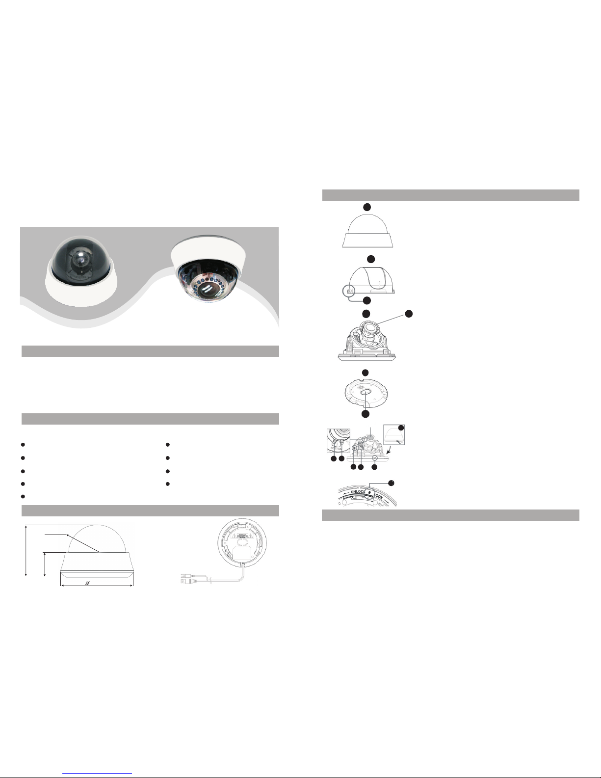
1. Cover dome: Covers the inner cover, lens, and main
body to protect them.
2. Inner cover: Covers the main body to protect it.
3. Wing locker: Push a long thin screwdriver into its
narrow spot and press it outward when you want to
remove the inner cover.
4. Main body: Includes a lens, a switch board, a PCB
board, screws, and such.
5. IR Leds.
6. Mount bracket: Used as a ceiling or wall fixture. It
ENG is fixed using three long tab screws provided in
the package.
7. Ceiling mount opener: Remove it for line connection
to the ceiling when it is installed on the ceiling.
8. Zoom lever: Using this lever, the lens zoom can be
adjusted and fixed.
9. Focus lever: The lens focus can be adjusted by
rotating it left or right. Rotate it clockwise for fixing.
10.Tilt fixing screw: Using this screw, the slope of the
lens can be adjusted and fixed.
11.Switch board: Includes two kinds of control switches
such as function switches and phase-control switches.
The board has eight function switches in the middle
and two phase-control buttons on each side of the
function switch area.
12.Groove mark: To attach the Main body to the Mount
bracket, align this groove mark on the Main body
with the wide groove in the CAMERA FRONT side
on the Mount bracket.
13.Locker: Used to open or close the Cover dome.
To open the cover dome, press the locker.
14.Lock releaser: Push it outward and rotate the main
body in UNLOCK direction when you want to
remove the Mount bracket from the Main body or to
remove the installed camera from the Mount bracket.
1
2
3
7
6
14
4
5
8
9
10
11
12
13
Len s
Setting switches
Overview
This is the high resolution dome camera eqiupped with the most advanced DSP technology and
features humanization design.
1) built-in 3 axis bracket 2)BLC,AGC,AES,MIRROR funtion 3)automatic switching between
color and B/W mode
2) built-in IR LED
Power: DC12V
Feature
Super low power consumption
Auto white balance
Low consunption
Dimensions
SR5 0mm
HLC/BLC
Day/night function
DNR (Digital Noise Reduction)
Varifocal lens
Built-in 3-axis bracket Mirror function
91m m
43m m
128 mm
Page 2

70
1.
you use auto iris lens, select this OFF.
2. BLC(Blacklight Compensation): ON/OFF
BLC ON: When the image is in front of strong background lighting, your camera
allows you to get the clear image.
BLC OFF: Deactivation
3. AGC (Auto Gain Control): ON/OFF
AGC ON: Gain is increased or decreased automatically depending on different
illumination.
AGC OFF: Deactivation
4. (H-MIRROR): when this switch is set to ON, the camera image is reversed
horizontally. If you want to monitor your site using a mirror, you can use this feature
to see the right image.
AES ON/OFF: AE: When you use fix or manual iris lens, select this ON. When
Installing camera
Before installation
You have to check wh et her the loc at ion (ceil in g or wall) ca n be ar five times
the weigh t of y our camer a.
Don’t let the c ab le to be caug ht i n imprope r pl ace or the el ec tric line c ov er
to be damag ed . Otherwi se i t may cause a b re ak do withi n or f ire.
Whe n in stallin g yo ur camera, do n’t al low any per so n to approa ch t he
install at ion site. I f yo u have any va lu able thin g su nder the plac e, m ove
them aw ay.
Before installing your camera, you have to read the following cautions:
355
90
Lens rotation
Note: The CAMERA FRONT sign on the Mount bracket should face the camera onitoring area.
Adjusting the camera direction
Cei ling mo unt ope ner
1.Pre ss the Lo cker bu tton on t he bott om of you r camer a and rem ov e the C ov er do me
from th e Main bo dy usin g the oth er hand . The M ai n bod y an d Inn er c over wi ll be
expos ed to you .
2.To instal l and adj ust you r camer a, you ha ve t o fir st r emo ve t he In ne r cov er. To
remov e the Inn er cove r from th e Main bo dy, pu sh a l ong t hi n screw drive r into th e
narro w spot of t he Win g lo cker an d press i t outwa rd to rem ove the c over.
3.Rem ove the M ount br acket f rom the M ain bod y by rota ting th e Ma in bo dy i n the
UNLOC K direc tion wh ile pus hing th e Lock re lease r ou t war d. I f it is n ot e asi ly
done, r otate t he Moun t brack et in the L OCK dir ectio n while h ol din g sm all h ol es
on the Mo unt bra cket.
4.Fix t he Moun t brack et to the l ocati on (cei ling or w all) wi th s upp li ed th re e scr ew s.
To install your camera
Tech. Specifications
When th e camer a is fixe d on the ce iling , you
can adj ust the c amera v iewin g angle . You can
rotat e your ca mera le ftwar d or righ tward
(Pann ing), a nd can ch ange th e slope o f your
camer a upwar d or down w ard (Til ti ng).
In case o f panni ng, the r otati on limi t of your
camer a is set to 3 55 degr ee (100 d egree
clock wise an d 255 deg ree cou nterc lockw ise).
The rot ation i s stopp ed by the S toppe r insid e
of the ca mera. F or pann ing con trol, f irst
unfas ten two s crews l ocate d on the bo ttom an d
In case o f tilti ng, you c an chan ge the sl ope of yo ur came ra from z er o to 90 d eg ree .
Howev er if the s lope an gle is un der 17 de gree, y ou can en count er a p art ia l ima ge h ide
probl em. To fix th e lo cat io n aft er a dju st ing t he t iltin g angle , use the Ti lt fixi ng scre ws.
To adj ust the f ocus an d zoom of y our cam era, us e th e Zoo m le ver a nd F ocu s le ver.
When yo u insta ll the ca mera on t he incl ined ce iling o r wall, y ou c an ro ta te th e ca mer a
lens to s ee a corr ect dir ectio n image .
rotat e in the di recti on you wa nt, and t hen fas ten the m to fix th e camer a.
Sensor
TV system
Sync mode
Resolution
S/N Ratio
Minimum
illumination
BLC
AES
Mirror
Power Supply Voltage
Power current
Lens
1/3" High S en sitivit y CC D
PAL/ NT SC
Interna l
52dB(AG C OF F)
OFF/N O
OFF/N O
OFF/N O
DC12V
Without I R
With IR:< 23 0mA(DC1 2V )
:<100mA (D C12V)
4-9mm
-10 C to 50 C (Wi th in85%RH )
Operation Temperature
-20 C to 50 C (Wi th in85%RH )
Operation Humidity
3-Axis
DNR
IR range
Without I R( NO); With I R( 20 M)
91mm(H) ╳ 1 28 mm(D)
Size(mm)
0TVL
Without I R
With IR
0.01Lux
0Lux (IR ON )
OFF/N O
Gain Control
372g
Weight
Model
 Loading...