

Page 1

DRIFTER
Owner's Manual
DESIGNED AND
MANUFACTURED IN
AUSTRALIA
022099 DOC DRIFTER User Man ual -A (Print)
DESIGNED AND
MANUFACTURED
IN AUSTRALI A
Page 2
Table of Contents
Introduction .. ....... .... ... .... ....... .... ....... .... ... .... ....... .... ... .... ..... 1
DRIFTER Basics ... ....... .... ... .... ....... .... ... .... ....... .... ... .... ....... .. 1
DRIFTER Display .. ....... .... ... .... ....... .... ....... .... ... .... ....... .... ... .. 2
Operation .. ... .... ....... .... ... .... ....... .... ... .... ....... .... ... .... ....... .... .... 2
Back-light .... .... ....... .... ... .... ....... .... ... .... ....... .... ... .... ....... .... .. 2
Battery on / off Switch .. .... ....... .... ... .... ....... .... ... .... ....... .... . 3
Clock set up ... .... ....... .... ... .... ....... .... ... .... ....... .... ... .... ....... ... 3
Set up .. .... ... .... ....... .... ... .... ....... .... ... .... ....... .... ... .... ....... .... .... 4
New Battery - Learning the Capacity ... ....... .... ... .... ....... .... . 5
Connectors .... ....... .... ....... .... ... .... ....... .... ... .... ....... .... ... .... ..... 5
Glossary ...... .... ... .... ....... .... ... .... ....... .... ....... .... ... .... ....... .... ... 6
Servicing ........ .... ....... .... ... .... ....... .... ... .... ....... .... ... .... ....... .... 7
Copyright © Setec Pty Ltd 201 2
Disclaimer
Setec Pty Ltd makes every effort to ensure the accuracy and sui tability of the information in
this manual, however makes no claim that this information is suitabl e or relevan t for
particular i ndivid ual situations.
ONE YEAR LIMITED WARRANTY
Setec Pty Ltd: Drifter BATTERY MO NI TOR
IMPORTANT:
Evidence of origi nal purch ase is required .
WARRANTOR:
Setec Pty Ltd
Warranty only available in original country of purchase.
ELEMENT OF WARRANTY
Warranty is only val id i f the un it has not been mod ified by the customer and has not been mi sus ed.
Setec Pty Ltd warrants to the orig in al retail own er for th e duration of th is warranty, its DRIFTER Battery M onitor
(herein referred to as the prod uct) , to be free from defects in materials and craftsma nsh ip with onl y the li mi tations or
exclu sions se t out bel ow.
Warranty du ration:
This warranty to the origi nal retail owner only, shall termi nate and be of no further effect ONE (1 ) year after the date of
original retai l sal e.
This warranty will be d eemed in val id if th e Product;
(A) Dam age d or not maintained as reasonable and necessary,
(B) Modi fied, altered or used as part of an y conversion kits, subassembl ies, or any con figu rations not sold b y setec.
(C) Improperly in stal led
(D) Repaired by someone other than an au thori sed Setec Pty Ltd repair agen t for a detect or mal function covered by
this warranty
(E) Used in conj un ction with any equ ipment or parts or as part of a system not man ufactu red by Setec Pty Ltd.
(F) Where the seri al numb er label or warranty vo id sticker of the prod uct has been removed or damaged beyon d
recogniti on.
Warranty only valid in the cou ntry of original retail sal e.
Our goods com e with g uarantee s that can not be excluded u nd er the Australian Consum er Law. You are en titl ed to a
replacement or refund for a major fai lu re and for compensation for any other reason abl y foreseeable loss or da mag e.
You are also entitled to h ave the g oods repai red or replaced i f th e goods fail to be of acceptable qual ity and the failure
does not amount to a m ajor fai lu re.
STATEMENT OF REMEDY
:
If in the event th at the product d oes not conform to this warran ty at any tim e while thi s warranty i s in effect, the
warrantor at i ts discretion, will repai r th e defect o r replace the prod uct and return i t to you with out charge for parts or
service. This warran ty does n ot provide for the reim bursement or payment of inci dental or conse quenti al damages.
PROCEDURE FOR OBTAINING WARRANTY:
In th e even t that the product d oes not conform to this warran ty, the Prod uct sh oul d be sh ipped or delivered, freight
pre-paid , to an au thorised Jayco d eal er (with evidence of original purchase, e g a copy of the sal es do cket, point of
purch ase), who wi ll repair or repl acem ent of u nit.
Or
Contact Jayco Head Office Service Centre on: 03 8792 21 36
Page 3
8
1
DRIFTER Basics
The Drifter product is compatibl e with any 1 2 V Lead-Acid battery including Valve-Regu lated
Lead-Acid (VRLA), Absorbed Glass M at (AGM ) and Gel batteries, as well as the traditional
non-sealed batteries.
The Drifter is permanently wired in to you r 1 2 V el ectrical system and continuously monitors
the battery voltage and charge/di scharge current. It u ses this information, tog eth er with
several parameters that are set by the user, to “model” the battery's behaviou r an d to
estimate the actual charge in the battery. This enabl es it to display a simple “fuel gauge” of
the capacity State of Charge (SoC) of the battery.
The current drain of the u nit is only 3 mA, which is mu ch less that the normal self-discharge
of a battery, so it will not materially affect the lifetime of a battery.
READ THIS FIRST!
BEFORE USING THE DRIFTE R, CAREFULLY READ THE
FOLLOWING INSTRUCTIONS, ESPECIALLY THE SAFETY NOTES
AND WARRANTY CONDITIONS
Introduction
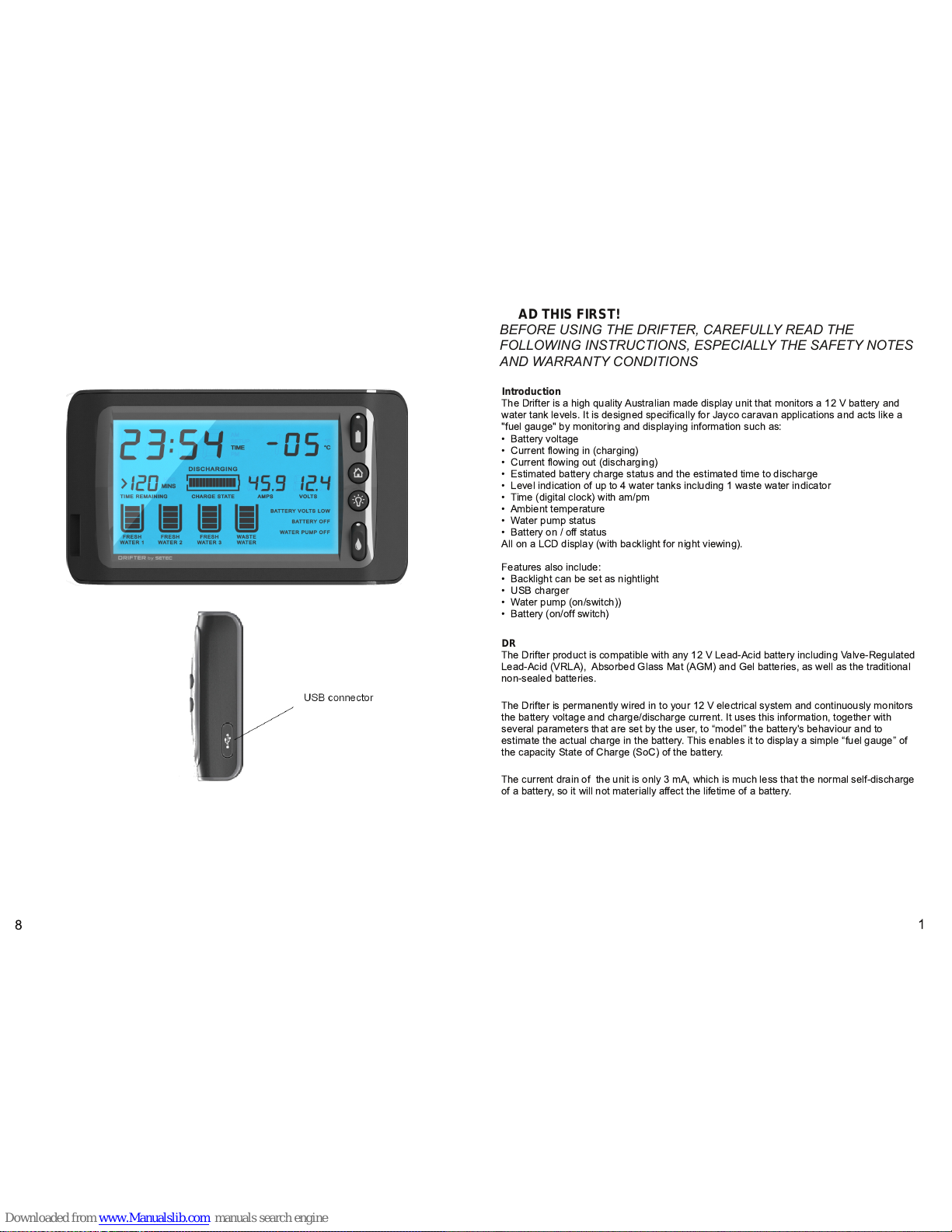
The Drifter is a high quality Au stralian made display unit that monitors a 1 2 V battery and
water tank levels. It is designed specifically for J ayco caravan appli cations and acts like a
"fuel gauge" by monitoring and displ ayi ng information such as:
• Battery voltage
• Current flowing in (charging)
• Current flowing ou t (dischargi ng)
• Estimated battery charge status and the estimated time to d ischarge
• Level indication of up to 4 water tan ks including 1 waste water i ndicator
• Time (d igital clock) with am/pm
• Ambient temperature
• Water pump status
• Battery on / off status
All on a LCD displ ay (with backlight for night viewing).
Features also include:
• Backligh t can be set as nightlight
• USB charger
• Water pump (on/switch))
• Battery (on/off switch)
Page 4
Servicing
The DRI FTER is manufactured in Australia with high quality components and should
requ ire no main ten ance beyond ensuring good connection to th e battery. It does h ave an
inline fuse to protect itself from power su rges, however if this fuse blows it should only be
replaced by a fuse of the same rating. A blown fuse i s an indicator of some other serious
fault in your power system, which should be checked by an appropriate professional auto-
electrician and warranty is voided if Drifter casing is damaged or opened.
Clean with a soft damp cloth, never use solvents to clean your DRI FTER.
Do not attempt to disassemble the DRI FTER.
There are no user-serviceable parts inside.
For all service enquiries
Contact Jayco Head Office Service Cen tre on:
03 8792 21 36
Operation
Power-up
On power-up the unit displays the M ain Screen.
Main Screen
The “Main Screen” displays the following data:
• Battery voltage
• Battery current together with a charge/discharge indication
• A bar-graph showing Battery State of Charge Level (SoC)
• The Time Remaining (Discharge) as a value in hours.
- If the value is larger then 1 99 h ours then the display shows “>1 99”
- If less than 2 hou rs display reverts to mi nutes
• Water tank levels in 25% increments
• Clock
• Water Pump Off (for switch in off position)
• Battery Off (for switch in off position)
Back-light
To turn On – Press the “Home” or “Light” bu tton . (The back-l ight will automatically turn off in
30 seconds).
To turn off – Press the light button.
Permanent back-li ght – M aki ng sure the back-ligh t is off, hold the light button for 3 seconds
(approx). The back-l ight will blink to indicate it is now permanently ON).
Turn permanent back-li ght off – Press the light button.
Note: There is no back-light brightness control.
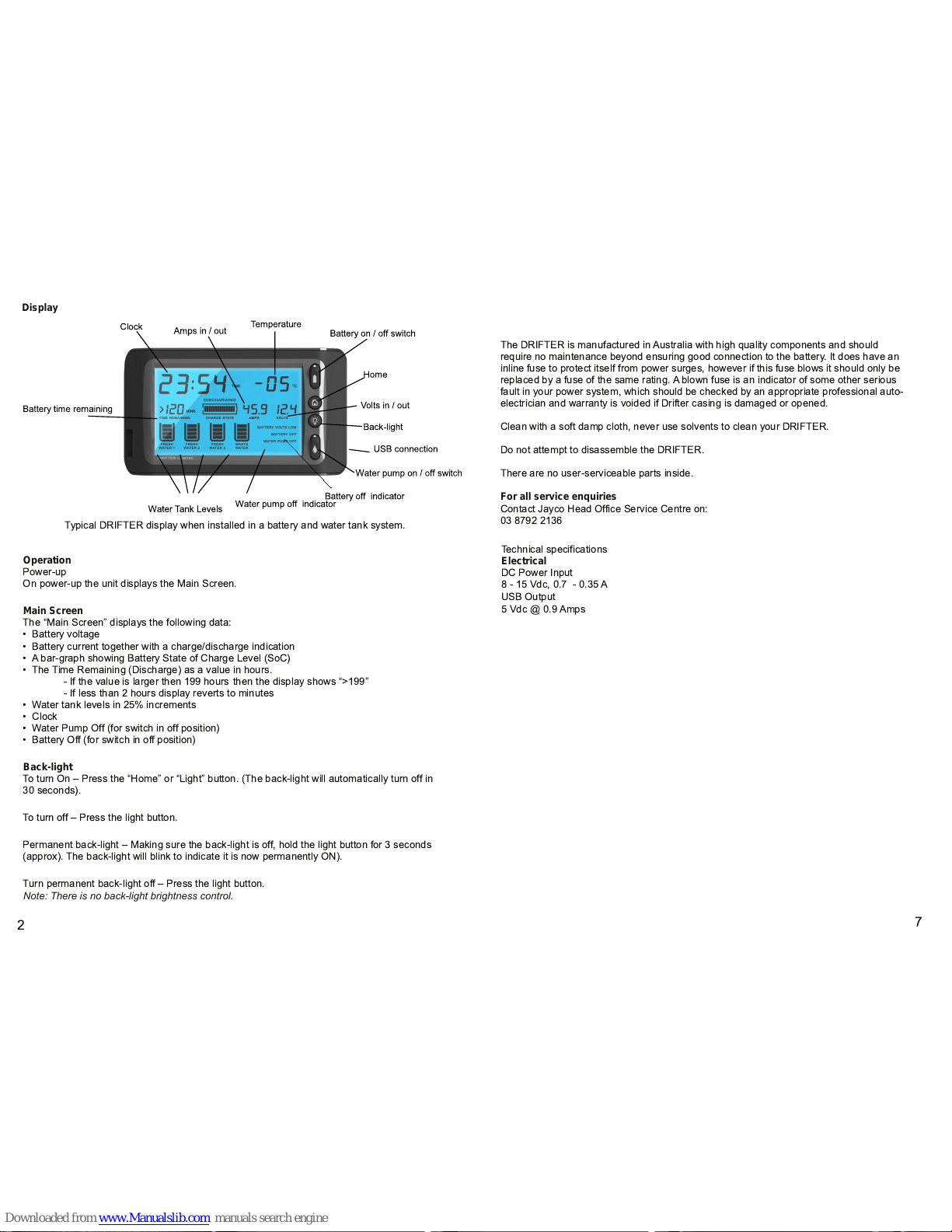
Typical DRIFTER display when installed in a battery and water tank system.
2
7
Techni cal specification s
Electrical
DC Power Input
8 - 1 5 Vdc, 0.7 - 0.35 A
USB Output
5 Vdc @ 0.9 Amps
Display
Page 5
Glossary
Terminal Voltage
The battery voltag e measured at the terminals. Measuring at the terminals allows any
voltage drop in any wiring to be eliminated from the measurement.
Nominal Capacity
The manufacturer's rated capacity for th e battery in Ah over a stan dard discharge ti me
(usually 20 hours).
Actual Capacity
The measured or learned capacity for a g iven battery und er service cond itions. Usually
thi s is less than the Nomi nal Capacity.
State of Charge SoC
The fraction of the current charge in the battery compared with the Actual Capacity of the
battery. The Drifter shall measure State of Charge to within ±20% of the true value within 2
cycles after a realign ment even t. (A realignment event will be defined as th e battery
reachin g 1 00% charge or 0% charge).
A Fully Charged Battery
A battery that has been charged to a sufficient voltage (typically above 1 3.7 V) that the
charge current has reduced to a low value (typically 1 00 mA).
Time Remaining
The tim e that the current discharge curren t can be maintained before the charge in the
battery reaches zero (i.e the terminal voltage reaches Floor Voltage).
Water TankMonitoring
The Drifter will display the water level for each of the water tanks. If ad ditional water tanks
are added the unit will auto-detect an d display the new unit's details.
USB Output
A U SB charging point is provided. Rated current 0.9 Amps.
3
6
Ambient Temperature
Room temperature in dication.
Battery on / off Switch
OFF position – This provi des a signal to control connection of the battery via the ST-III
Power supply. It will al so disable the USB output. The LCD di splays “BATTERY OFF”.
Water Pump on / off Switch
Power to the water pu mp is con trolled by activating the "pump switch" located on the front
panel. The LCD displays the “WATER PUMP OFF” annunciation when i n the off posi tion.
Waste Water Display
When top indicator bar is blinking, this ind icates that the the tank is full.
Note:
If water tank switch is turned off the display will remain constant at its last reading. To
obtain a current reading turn water pump on and the display will refresh.
Clock
1 2 Hour clock with AM , PM indication.
Clock Setup Mode
Clock set up mode is entered by holding down the set up key for at l east 5 seconds wh en in
normal display mode withou t the Back light key being pressed .
Clock Setup – Hold th e “Home” button for at least 5 seconds when i n normal display.
The clock display will change:
Firstly the “minutes” digits wi ll flash. To ch ange the “minutes” click the “back-li ght” button to
increase.
To change “Hours” press “Home” button and the “Hours” will flash. Press “back-light” button
to increase the hours.
Note: Clicking on the “Back-light” button incremen ts the value by 1, and holding the “Backlight” button down causes the value to increment continually at a rate of 1 unit per second.
The value rolls over to zero on reaching the maximum value, note that incrementing the
minutes value beyond 59 does not increment the hours value.
If no keys are pushed for a period of 1 5 seconds, then the clock is set to the indicated
values an d normal display mode resumes.
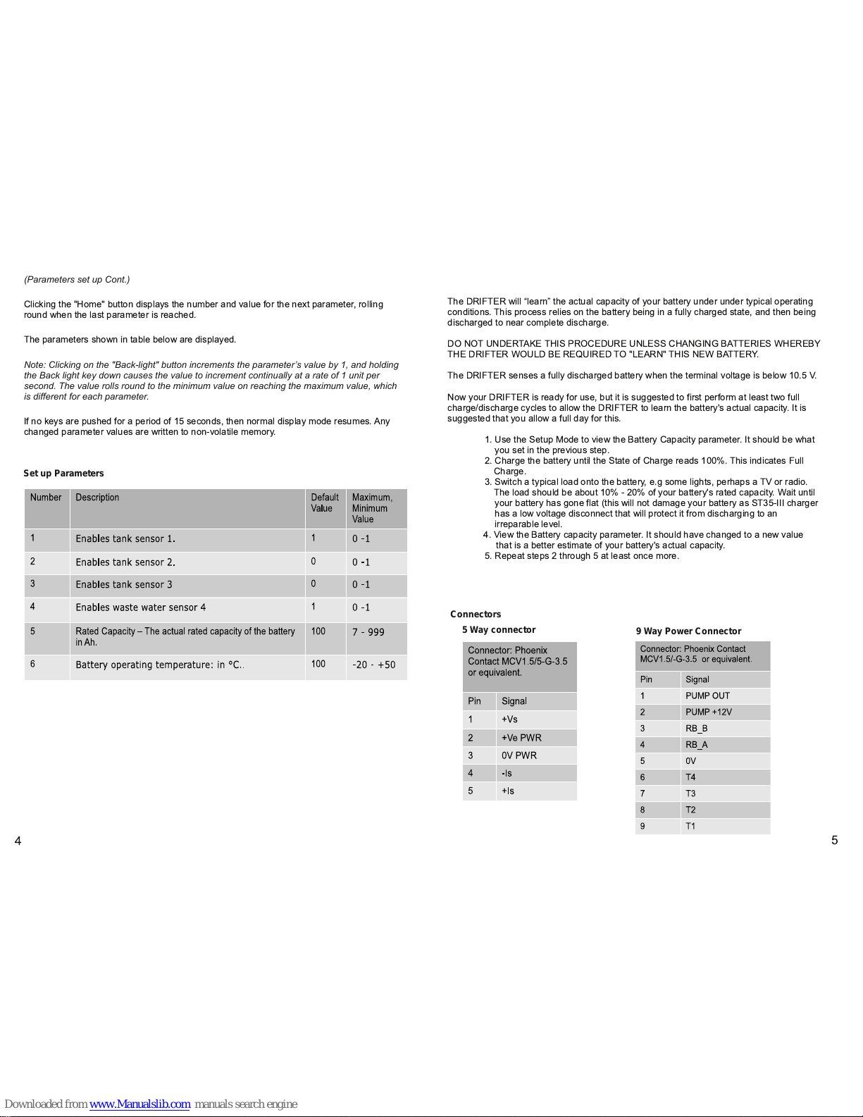
Set Up
THESE PARAMETERSARE FACTORY SET AND UNLESS YOU ARE CHANGING
BATTERIES, THERE IS NO NEED TO ENTER THIS MODE.
Parameter Set up Mode is entered by holding down the "Home" and the "Back-l ight" buttons
for at least 5 seconds when in normal d isplay mode.
When Parameter Set up Mode is entered:
• The clock digits show the valu e of the parameter.
• The SETUP annu nciator is on.
• The temperature digi ts show the parameter number.
• All other LCD segments are off.
Page 6
NEW BATTERY- LEARNING THE CAPACITY
The DRI FTER wi ll “learn” the actu al capacity of your battery under under typical operating
conditions. Th is process relies on the battery being in a full y charged state, and th en being
discharged to near complete discharge.
DO NOT UN DERTAKE THIS PROCEDURE UNLESS CHANGING BATTERIES WH EREBY
THE DRIFTER WOULD BE REQU IRED TO "LEARN" THIS NEW BATTERY.
The DRI FTER senses a fully disch arged battery when the terminal voltage is below 1 0.5 V.
Now your DRI FTER is ready for use, but it is suggested to first perform at l east two full
charge/d ischarge cycles to allow the DRIFTER to learn the battery's actu al capacity. It is
suggested that you allow a full day for this.
1 . Use the Setu p M od e to view the Battery Capacity parameter. I t shou ld be what
you set in the previous step.
2. Charge the battery u ntil the State of Charge reads 1 00%. This i ndicates Fu ll
Charge.
3. Switch a typical l oad onto the battery, e.g some lights, perhaps a TV or radio.
The load should be about 1 0% - 20% of your battery's rated capacity. Wait u ntil
your battery has gone flat (this will not damage your battery as ST35-I II charger
has a low voltage disconn ect that wil l protect it from discharging to an
irreparable level.
4. View the Battery capacity parameter. It should have ch anged to a new value
that is a better estimate of your battery's actual capacity.
5. Repeat steps 2 through 5 at least once more.
4
5
Connectors
9 Way Power Connector
(Parameters set up Cont.)
Clicking the "Home" button displays the number and valu e for the next parameter, rolling
roun d when th e last parameter is reached.
The parameters shown in table below are displayed.
Note: Clicking on the "Back-light" button increments the parameter’s value by 1, and holding
the Back light key down causes the value to increment continually at a rate of 1 unit per
second. The value rolls round to the minimum value on reaching the maximum value, which
is different for each parameter.
If no keys are pushed for a period of 1 5 seconds, then normal display mode resu mes. Any
changed parameter values are written to non-vol ati le memory.
Set up Parameters
5 Way connector
 Loading...