


Operating Instructions
We reserve the right to change the contents
due to product innovation or technical improvement.
Please state type of equipment and serial
number when contacting us.
Please read these instructions and keep the
manual safe!
Please observe and follow the safety notes!
Sesotec GmbH
Regener Straße 130 * D-94513 Schönberg
Telephone: +49 (0) 8554 308-0 * Fax: +49 (0) 8554 2606
E-mail: info@sesotec.com
Internet: http://www.sesotec.com
Service: Telephone: +49 (0) 8554 308-180
Control Unit
PRIMUS+
1 PRIMUS-PLUS-BA-CU-EN-5136.docx

Manufacturer:
Sesotec GmbH
D-94513 Schönberg, Germany
Contact:
Sesotec GmbH
Regener Straße 130
D-94513 Schönberg, Germany
Tel.: +49 (0) 8554 3080
Fax.: +49 (0) 8554 2606
E-mail: info@sesotec.com
Internet: www.sesotec.com
Represented by:
2 PRIMUS-PLUS-BA-CU-EN-5136.docx

Contents
Contents
1 General information 6
1.1 Introduction 6
1.2 Field of application 6
1.3 Application reasons 6
1.4 System identification 6
1.5 Symbols used 6
1.6 EC DECLARATION OF CONFORMITY 6
1.7 Overview 7
2 Design and method of operation 8
2.1 Functional principle 8
2.2 Functional and control elements 9
2.2.1 Operating module with LCD graphic display 9
2.2.2 Cable glands 9
2.2.3 PRIMUS+ / IO electronics board 10
2.2.4 PRIMUS+ / CU electronics board 12
3 Dimensions and technical data 13
3.1 Technical data sheet, see annex 13
3.2 Supply connections, see technical data sheet in the annex 13
3.3 Environmental conditions for operation, storage, and transport 13
3.4 Noise levels 13
4 Safety 14
4.1 Intended use 14
4.2 Safety signs 14
4.3 Dangers arising from non-compliance with safety notes 14
4.4 Safety information for operators 14
4.5 Safety information for operation, maintenance and cleaning 15
4.6 Safety information for commissioning 15
4.7 Safety information for storage and transport 15
4.8 Notes on residual risks 15
4.9 Notes on stable standing requirements 15
4.10 Consequences of unauthorised modification 15
4.11 Improper use 16
5 Commissioning 17
5.1 Mechanical mounting 17
5.2 Connection of the equipment 17
5.2.1 PRIMUS+ / IO electronics board (control electronics board) 18
5.2.2 Electrical connections 18
5.2.3 PRIMUS+ / CU electronics board (evaluation electronics board) 19
5.2.4 Electrical performance 20
5.2.5 Drawing of input / output connections 20
5.2.6 Electrical connection of the equipment 21
5.2.6.1 Mains supply via safety socket 21
5.2.6.2 Mains supply via terminal box 21
5.2.7 Behaviour of machine at start up 22
5.2.8 Relays – operating status 23
6 Menu / Operation PRIMUS+ 24
6.1 General Operation 24
3

Contents
6.2 Quick Start 25
6.2.1 Language Selection 25
6.3 Menu Structure 26
6.3.1 Main menu 26
6.3.2 Function menu items 26
6.3.3 Settings menu items 26
6.3.4 Output menu 27
6.3.5 Setup menu 28
6.3.6 Operating mask 32
6.3.7 Change product 33
6.3.8 Auto-Set 34
6.3.9 Product parameter 35
6.3.10 Conveying speed 35
6.3.11 Output 36
6.3.11.1 Output adjust 36
6.3.11.2 Output lock 37
6.3.11.3 Monitoring 37
6.3.11.4 Output Level 37
6.3.11.5 Output options 38
6.3.12 Setup 38
6.3.12.1 Logbook 39
6.3.12.2 Clear logbook (Menu item requires login) 41
6.3.12.3 Show counter 41
6.3.12.4 Device-Info 42
6.3.12.5 Revision 42
6.3.12.6 Change password (menu item requires login) 43
6.3.12.7 Language 43
6.3.12.8 Clock/Date (menu item requires login) 43
6.3.12.9 Setup options (menu item requires login) 44
6.3.12.10 Units (menu item requires login) 44
6.3.12.11 Frequency deviation (menu item requires login) 44
6.3.12.12 Factory settings (menu item requires login) 45
6.3.12.13 Login 45
6.3.12.14 Logout 45
6.3.12.15 Air pressure monitoring (option) (menu item requires login) 45
6.3.12.16 Flap monitoring (option) (menu item requires login) 46
6.3.12.17 External error (option) (menu item requires login) 46
6.3.12.18 Ejection monitoring (option) (menu item requires login) 46
7 Errors and error remedying 47
7.1 Error messages 47
7.1.1 Receiver voltage too high 47
7.1.2 Receiver faulty 47
7.1.3 Transmitter faulty 47
7.1.4 Transmitter over temperature 47
7.1.5 Hardware CU 48
7.1.6 Hardware IO 48
7.1.7 Communication IO 48
7.1.8 Watchdog 48
7.1.9 Memory error 48
7.1.10 Short circuit MV 48
7.1.11 Connection MV 48
7.1.12 Air pressure 49
7.1.13 Diverter position 49
7.1.14 Sensor 1 faulty 49
7.1.15 Sensor 2 faulty 49
7.1.16 Filling level 49
7.1.17 External error 50
7.2 Undefinable activation of the switching outputs 50
7.3 Replacing the backup battery 51
4

Contents
7.4 Replacement of electronic boards 52
7.4.1 Replacing the CU electronics board PRIMUS+ 52
7.4.2 Replacing the IO electronics board PRIMUS+ 53
7.4.3 Replacing the display board 53
8 Maintenance and cleaning 54
8.1 Maintenance 54
8.2 Cleaning 54
8.2.1 Hints for cleaning 54
8.2.2 Cleaning instructions 54
8.2.3 Care advice for stainless steel 54
9 Spare parts 55
9.1 Spare parts view 55
9.2 Spare parts list 56
10 Shipping, preservation, waste disposal, transport, storage 57
10.1 Shipping, preservation, waste disposal 57
10.2 Transport 58
10.3 Storage 58
11 Annex 59
5
1. General information
Symbol
Signal word
Meaning
Danger
Warning: Possibility of severe or even fatal personal injuries.
Danger
The lightning symbol is an explicit warning that there is danger from
electric current.
Warning
Warning: Possibility of minor personal injuries or property damage.
Caution
Warning: Possibility of defects or destruction of the equipment.
Important in-
formation
Indicates an important information for the function.
Important
hint
Indicates an important hint for the function.
1 General information
1.1 Introduction
The texts and illustrations in this instruction manual are for the exclusive purpose of explaining how to
operate and handle the control unit. The manufacturer accepts no responsibility for damage resulting
from the use or misuse of this equipment. All appropriate safety rules and regulations for the use of
this equipment must be adhered to. If you have any questions with regard to the installation and operation of this equipment please do not hesitate to contact us.
This instruction manual may not be copied, saved on computer or otherwise reproduced without the
prior permission of the manufacturer. Nor may any extract of this instruction manual be similarly reproduced.
1.2 Field of application
The PRIMUS+ control unit is used in combination with Sesotec metal detectors and separators in the
plastics, wood, food, chemical, and in a special version also in the pharmaceutical industry. Depending
on the respective version, these systems inspect packed, unpacked, or piece products, and bulk materials for magnetic and non-magnetic metal contaminations.
Of course they also are suitable for similar applications in other branches of industry.
1.3 Application reasons
Product liability
ISO 9000
TQM (Total Quality Management)
Protection of machines and quality assurance
1.4 System identification
The information in this instruction manual only applies to the PRIMUS+ control unit. A label with the
respective data is attached at every system.
1.5 Symbols used
1.6 EC DECLARATION OF CONFORMITY
(See annex – EC DECLARATION OF CONFORMITY)
6
1. General information
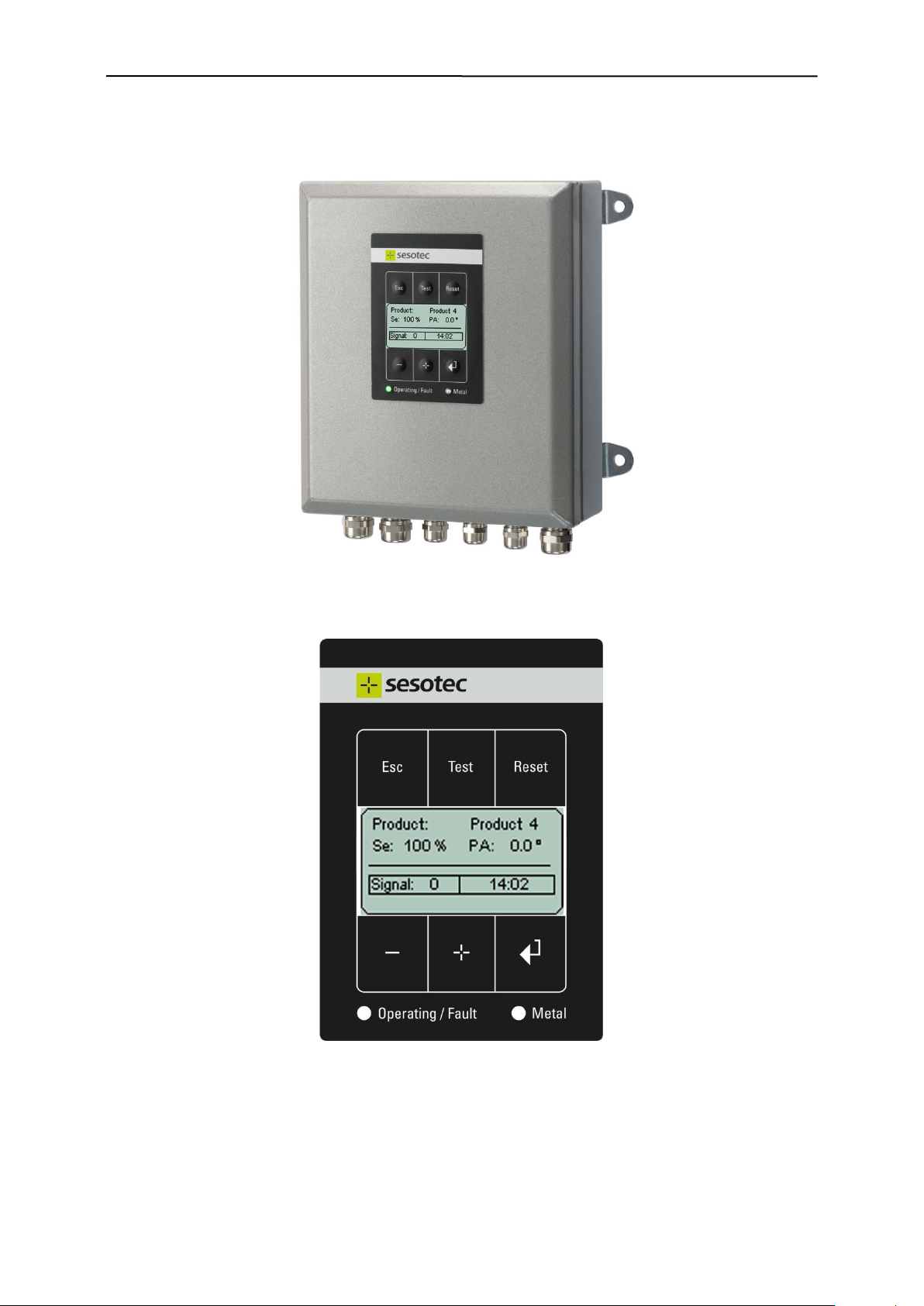
PRIMUS+ Control Unit
Graphic display
1.7 Overview
7

2. Design and method of operation
R
e
c
e
i
v
e
r
T
r
a
n
s
m
i
t
t
e
r
R
e
c
e
i
v
e
r
Detection coil
Signal amplifier
Analog/digital
converter
LCD graphic
display
Memory for
10 products
CU elec tronics
IO electr onics
Power
supply
CPU
Relay
I/O in terface
Oscillator
Control Unit PRIMUS+
Control panel
Logbook
real time clock
CP U
Monitorin g
For reasons of the employed technology it is not possible to guarantee 100% metal
detection.
2 Design and method of operation
2.1 Functional principle
The metal detector works with the so-called "balanced coil" principle:
The transmitter winding in the search coil creates a high-frequency electromagnetic field, which is received by symmetrical placed receiver windings. The windings are connected against each other;
when undisturbed, the system is in balance.
An electrically conductible object within the detection area disrupts this balance and the electronic creates a switch signal.
A "teach in process” allows to suppress the conductivity of the product itself. Deviations from the
taught-in product are usually caused by metal contaminants, which are detected by the device with
high precision.
The metal detector is equipped with comprehensive test and analysis software to ensure fault-free operation and retracing of product errors.
8
2. Design and method of operation
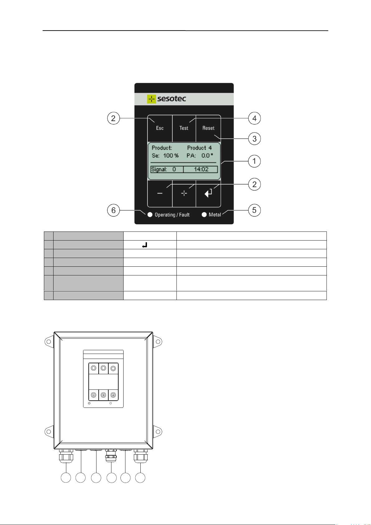
1
Graphic display
LCD module
Display of operating and input masks
2
Operator keys
+ , - , , Esc
For operation and machine setting
3
Function key
Reset
Reset to restore the unit after metal or fault signal
4
Function key
Test
Test function for metal detectors
5
Metal LED
Metal
Lights red when metal detected
6
Operating / Fault LED
Operating
Lights green in normal operating mode, metal detection active
6
Operating / Fault LED
Fault
Lights red in case of fault and error
11
98 10 127
Ope rating/ Fault Metal
Esc Test
Reset
(7) Cable gland for the mains cable
(8), (9), (11) Cable gland for option
(10) Cable gland for free use
(12) Cable gland for connecting the detector coil
2.2 Functional and control elements
2.2.1 Operating module with LCD graphic display
2.2.2 Cable glands
9
2. Design and method of operation
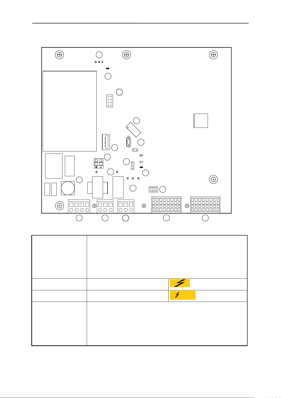
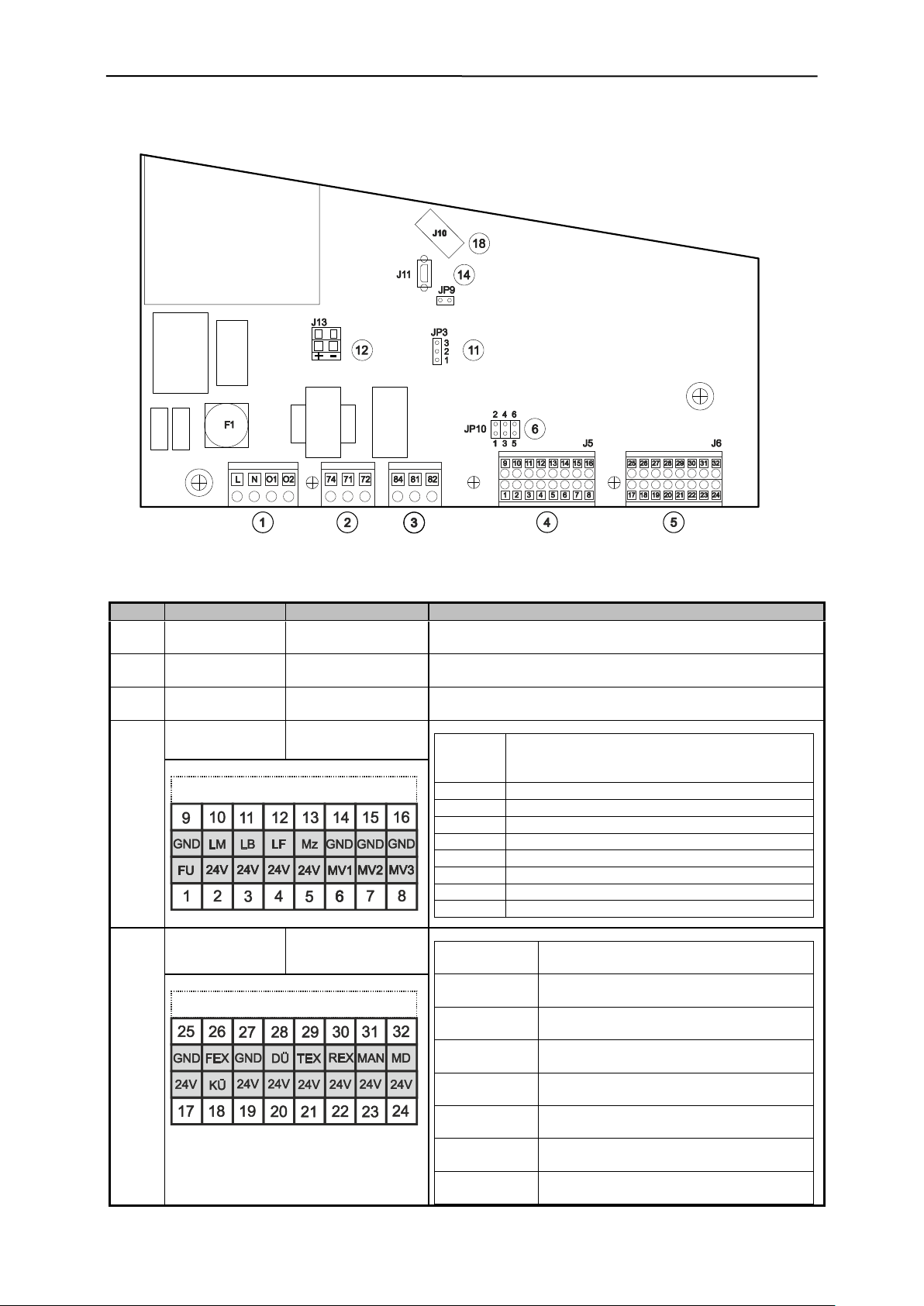
Connectors and terminals:
(1) "Mains/Option" L/N: Control unit power supply
O1/O2: Optional 24V module power supply
(2) "Relay metal" Potential free change over contact
(3) "Relay fault" Potential free change over contact
(4) "Switching outputs" J5, connector, magnetic valves, signal combi., etc.
(5) "Switching inputs" J6, connector, sensors, switches, etc.
(12) "MV voltage external" J13, connector 24V external (option)
(18) "CU connection" J10, plug connection to CU electronics
Elements connected to
mains voltage:
(1) "Connector, Mains/Option"
(10) "Mains fuses
Elements connected to
external voltage:
(2) "Connector, relay metal"
(3) "Connector, relay fault"
Vorsicht
Fremdspannung
Light diodes:
(7) "Monitor LED, MV1-3" LD 10, magnetic valve (MV1)
LD 9, magnetic valve (MV2)
LD 8, magnetic valve (MV3)
(9) "Monitor LED, relay" LD 11, relay fault (84, 81, 82)
LD 12, relay metal (74, 71, 72)
(17) "Monitor LED, Vcc” LD 1, +24V
LD 2, +10V
LD 3, +3.3V
9
25 26 27 28 29 30 31 32
1
17 18 19 20 21 22 23 24
10211312413514615716
8
8171N 8474L 8272O1 O2
TP2
JP9
F1
JP10
LD10
LD9
LD8
LD11
LD12
J8
J10
J14
J13
LD1
LD2
LD3
TP1
1
J5 J6
JP3
3
2
1
3
8
1
4
6
2
5
7
J11
11 3 5
2 4 6
2
3
4
5
6
7
8
9
14
13
3
11
15
(GND)
(GND_24V)
2
17
10
16
12
18
2.2.3 PRIMUS+ / IO electronics board
10
2. Design and method of operation
Jumper:
(6) "MV connection monitor" JP10, 1-2, MV1
JP10, 3-4, MV2
JP10, 5-6, MV3
(11) "MV voltage supply" JP3, 2-1 external 24V (connector J13 +/-)
JP3, 2-3 internal, 24V (default)
(15) "Service jumper" J8, 5-6, plugged, enable, program update
Test points:
(8) "GND_24V” TP2, magnetic valves (MV1- MV3)
(16) "GND" TP1, IO electronics
Interface/plug connectors:
(14) "Program update" J11, mini USB, (only for trained staff)
JP9, USB selection (jumper plugged)
(13) "Data backup" J14, USB interface (system / product data)
JP9, USB selection (jumper open)
Fuse
Description
Type
F1
Mains supply
1.6A slow-blowing 1500A @ 250VAC 5x20mm
11

2. Design and method of operation
Connectors and terminals:
(1) "Receiver" J10, input signal from the detection coil
(2) "Transmitter" J7, output signal to the detection coil
(9) "Service interface" J11, diagnostics interface
(11) "FFC connector" J5, ribbon cable connector to the display module
(12) "Memory" J4, system / product data
Test points:
(3) "Transmitter signal" TP7, sine signal ( 25Vss) to the detection coil
(6) "GND" TP8, TP19, reference ground for all signals
Jumper:
(8) "Service jumper" J2, 5-6, plugged, enable, program update
Interface/plug connectors:
(10) "Program update" J9, mini USB, (only for trained staff)
(JP2, observe jumper position)
Light diodes:
(5) "Monitor LED,s, Vcc" LD 5, +24V
LD 6, +5V
LD 7, -5V
LD 8, +15V
LD 9, -15V
LD 10, 3.3V
(4) "Monitor LED’s" LD 4, green, operating status
LD 3, red, fault status
Memory:
(12) "Memory devices" J4, device and product data
(7) "Battery" BT1, for real-time clock
2.2.4 PRIMUS+ / CU electronics board
12

3. Dimensions and technical data
3 Dimensions and technical data
3.1 Technical data sheet, see annex
3.2 Supply connections, see technical data sheet in the annex
3.3 Environmental conditions for operation, storage, and transport
The environment of the control unit should be free of any chemical vapours such as softeners, chlorine, or similar substances. The control unit must not be exposed to direct sunlight or to other environmental influences (rain, snow and storm). For ambient temperature conditions for operation,
storage, and transport please refer to the technical data sheet in the annex.
3.4 Noise levels
Sound pressure level measurements (in acc. with DIN 45 635)
Peak value of sound pressure level at a distance of 1m from the machine surface and 1.60m above
the floor, LpA, 1m, max.
Result:
Idling: < 70 dB(A)
Activated: < 90 dB(A)
We reserve the right to change the contents due to product innovation or technical improvement.
13
4. Safety
The following safety and danger notes are intended for your protection, for the protection
of third parties, and for the protection of the equipment. The safety notes therefore should
always be observed!
The equipment is intended for use in the following fields of application and only in combination with a corresponding detection coil of series GLS, C-SCAN DLS, P-SCAN RP: Suction/pressure conveyor applications, free-fall applications, and applications at a conveyor
belt. The equipment can be used in the plastics, food, animal feed, recycling, and chemical
industry. Basically it is possible to also use the system in other applications than the intended use stated herein, but such applications always require the prior consultation and
approval of Sesotec GmbH.
Symbol
Signal word
Location
Meaning
Mains voltage
Cover of
the electronics
housing
This symbol indicates that mains voltage is used in the electronics housing, and that any connected external circuits
(e.g. at the metal relay) also may be energised. There is
danger of electric shocks due to the presence of mains voltage.
Connection symbols:
"Mains" (1)
"Metal" (2) und "Fault" (3)
Any non-observance of safety notes constitutes a danger for life and health.
The control unit PRIMUS+ may only be operated in the intended purpose and in a perfect functioning condition, especially the cover of the electronic housing has to be closed during operation. Entered moisture has to be removed! All fixed warning signs on the equipment may not be
removed and have to be in a well recognizable condition. The operating instructions always
have to be in a legible condition and complete available. Prior to commissioning always make
sure that the applicable accident prevention regulations are observed. If the control unit is
not mounted at the detection coil, it must be properly and firmly fastened by means of the
four screws. The operator must make sure that the equipment is mounted at an ergonomic
height for operation. The operator may only appoint qualified personnel for operation, mainte-
nance and repair work. If potentially explosive materials are examined, the pertinent regulations must be observed.
Emitted interference
Test report according to the provisions of:
BGV B11:2001-06
Regulations of the professional association for safety and
health at work.
Accident prevention regulations for electromagnetic fields.
E DIN VDE 0848-3-1: 05-2002
Safety in electrical, magnetic, and electromagnetic fields,
part 3-1: Protection of persons with active implants in the
frequency range of 0Hz to 300 GHz.
In the area where the operating personnel is working the electromagnetic field of the metal
4 Safety
Our equipment conforms to all official technical safety regulations. However, as a manufacturer we believe it is our duty to make you aware of the following information.
4.1 Intended use
4.2 Safety signs
4.3 Dangers arising from non-compliance with safety notes
4.4 Safety information for operators
14
4. Safety
detector or separator does not exceed the limits stated in the provisions. Therefore there
are no health impairments due to electromagnetic fields in this area for persons and for
wearers of medical implants such as cardiac pacemakers. Inside the coil of round or
closed tunnel coils, or on the surface of flat coils, the limits may be exceeded depending
on design and system version. If work is to be performed inside or at the search coil, persons and wearers of medical implants such as cardiac pacemakers may only enter the
equipment when it is turned off, provided that size and design allow this.
Because of energised components in the electronics housing there is a risk of injuries due
to electric shock or burns. During operation the cover of the electronics housing must be
kept closed. Only qualified personnel may operate and clean the equipment.
If the electronics housing must be opened for maintenance or cleaning purposes, remove
any dirt and moisture from the electronics housing, so that no larger amounts may get into
the interior. Always disconnect the power supply and any connected external circuits before opening the cover. Any moisture that has penetrated into the interior must be removed from the electronics housing. If any maintenance work must be performed in
energised condition, e.g. battery replacement, such work may only be performed by a
qualified electrician under strict observation of the attached warning labels and with due
regard to standard approved rules of electrical engineering.
No safe condition is established when outputs are switched "inactive" (with "Disable Outputs", "Bypass", or "Output level inactive".
For any maintenance work the compressed-air and power supply of the machine must always be disconnected, and any existing pneumatic cylinders must be vented.
To avoid any injuries due to energised parts in the electronics housing, the information in
5.1 and 5.2 must always be observed.
Always observe the information in paragraph 10 to avoid any transport damage and personal injuries.
Electrical circuits may still be live even after having been isolated from the mains. Switch
off immediately if a fault occurs.
To avoid any loss of stable standing, the information for transport, commissioning and operation must always be observed. Always make sure that the fastening screws of the control unit are tight during operation. When storing or transporting the control unit, place it on
the closed rear panel of the housing.
Unauthorised modification or repair will invalidate all manufacturer declarations and guarantees.
4.5 Safety information for operation, maintenance and cleaning
4.6 Safety information for commissioning
4.7 Safety information for storage and transport
4.8 Notes on residual risks
4.9 Notes on stable standing requirements
4.10 Consequences of unauthorised modification
15

4. Safety
For other applications as enumerated in 4.1 the control unit PRIMUS+ intended for – that
is regarded as inadmissible operation. Improper use also includes operating the equipment with excessive mechanical, static or dynamic loads (e.g. heavy machine parts or
strong vibration). It is furthermore not permitted to inspect any aggressive materials on the
conveyor, such as materials containing lyes, acids, and solvents, or materials that react to
electromagnetic fields, or living persons or animals, and to operate the system in an Ex
protection area.
4.11 Improper use
16
5. Commissioning
In order to meet CE conformity all cable outside of the housing has
to be shielded. The shields must be grounded immediately after the
cable gland.
Housing
Shield
Cable
5 Commissioning
5.1 Mechanical mounting
Ensure stable and non-vibrating installation! In house mounting and operation. Do not install the
system in an explosion proof zone.
Do not install the detection coil and the electronic unit in the vicinity of interference fields (large
electric motors and frequency converters!) The distance depends on the power consumption of the
motor or of the frequency converter (value for orientation: 5 m).
Mount the control cabinet by using the provided bores. I.e. at a wall or frame (dimensions are shown in
the outline drawings). Pay attention to good stability, as the weight of the control unit is approx. 4 kg.
Never install the electronic unit in other switchgear cabinets, because this may lead to interference
effects. (E.g. from contactor controls)!
Cable lengths may only be modified after consultation with "Sesotec". Use only original cables. Lay
the connecting cable in fixed installation apart from other cables (e.g. fix it with nailing clips or lay it
in a cable duct).
If several metal detector systems are used, the distance of the detection coils must not be less than
2m, if these coils stand side by side. If the coils are arranged opposite to each other, the distance
must not be less than 10 m. These values apply to large systems; for smaller systems the distances may be reduced to 50 cm. If, for reasons of space, these distances cannot be observed, please
contact Sesotec service!
Do not install the equipment in such a way that operation of the mains cut-off switch is hindered in
any way!
5.2 Connection of the equipment
17
5. Commissioning
Pos.
Connection
Type of connection
Function
(1)
"Mains/Option"
Connector for mains
supply
L/N: Electronics power supply
O1/O2: Optional 24V module power supply connector
(2)
"Relay metal"
Voltage free
relay contact
Normal operation: Contacts 71 and 72 closed
On metal detected Contacts 71 and 74 closed
(3)
"Relay fault"
Voltage free
relay contact
Normal operation: Contacts 81 and 84 closed
In case of fault: Contacts 81 and 82 closed
(4)
"Outputs"
Switching outputs
24V
J5
Switching functions
MV = magnetic valve connection
( =24V to GND or = 0V to 24V)
1 – 9
, FU: Not assigned
2 – 10
, LM: Lamp metal
3 – 11
, LB: Lamp operation
4 – 12
, LF: Lamp fault
5 – 13
, Mz: Ext. metal counter
6 – 14
or , MV1, (after system setup)
7 – 15
or , MV2, (after system setup)
8 – 16
or , MV3, (after system setup)
(5)
"Inputs"
Switching inputs 24V
J6
Switching functions
24V, NPN or PNP switching
17 – 18 – 25
KÜ: Flap monitoring
PNP or NPN (dep. on application)
19 – 26 – 27
FEX: Fault external
PNP or NPN (dep. on application)
20 – 28
DÜ: Compressed-air monitoring
NPN
21 – 29
TEX: Test external
NPN
22 – 30
REX: Reset external
NPN
23 – 31
MAN: Manual separation
NPN
24 – 32
MD: Deactivate metal detection
NPN
J5J5
J6
5.2.1 PRIMUS+ / IO electronics board (control electronics board)
5.2.2 Electrical connections
18

5. Commissioning
Pos.
Connection
Type of connection
Function
(6)
"Jumper JP10"
Placement,
connection monitoring MV1 – MV3
active / inactive
JP10
Functions
Jumper plugged, monitoring inactive
Jumper open, monitoring active
1 – 2
MV1 connection monitoring
3 – 4
MV2 connection monitoring
5 – 6
MV3 connection monitoring
Remove jumper when valve is connected
(12)
"+24V external"
+24V, external supply of magnet valve
connection
Supply MV1 / MV2 / MV3 with external 24V.
Necessary when high-power valves are used, if total valve
power >6W
JP3
Function
Selection, supply of magnet valve connection
2 – 3
MV supply 24V internal
2 – 1
MV supply 24V external through connector J13
Pos.
Connection
Type of connection
Function
(1)
"Receiver"
Connection for detection coil:
Receiver
JP10
Functions
1
Receiver signal
2
Receiver signal
3
Reference ground for receiver signal
4
- 5V 5 + 5V
(2)
"Transmitter"
Connection for detection coil:
Transmitter
JP7
Functions
1
Transmitter voltage
2
Reference ground for transmitter voltage
3
Not assigned
4
Transmitter switch-over signal
5.2.3 PRIMUS+ / CU electronics board (evaluation electronics board)
19

5. Commissioning
Potential-free relay contacts
250V 3A with alternating voltage
120V 3A with direct voltage
For the potential-free relay circuits fusing must be provided outside the equipment.
Switching outputs (MV1, MV2, MV3)
Switching outputs (LM, LB, LF, Mz)
Maximum current load: 250 mA
Maximum current load: 150 mA
Switching inputs
Connection of make contacts against+24 V,
connection of sensors (PNP, NPN)
total max. permissible current load 24V / 150 mA
Switching outputs
J5
9
10
11 12 13 14
15 16
1 2 3 4 5 6
7
8
NC
Not
used
LM
Light
metal
LB
Light
operating
LF
Light
error
1
2
3
MZ
Metal
counter
MV1 MV2 MV3
Switching inputs
J6
Sensor1
25 26 27 28 29 30 31 32
Sensor2
17 18 19 20 21 22 23 24
P
Pressure
switches
External
test
External
Reset
Manual
separation
Disable
metal
detection
At J5, J6 only circuits that are isolated from the mains supply by way of double insulation
(SELV circuits) may be connected.
5.2.4 Electrical performance
5.2.5 Drawing of input / output connections
20

5. Commissioning
Maximum cable length for external components, switches and sen-
sors is 15 m.
Only shielded cables should be used.
The shields must be attached directly to the electronics housing.
Housing
Shield
Cable
1
Conductor 1 (black)
to terminal L
2
Conductor 2 (black)
to terminal N
3
Conductor PE (yellow/green)
to earth connection
The following procedures should only be undertaken by qualified personnel. Before removing cover plates etc. make sure the equipment is isolated from mains or external voltage.
If the mains plug is removed, a terminal box and a suitable mains disconnector switch
with corresponding labelling/marking must be installed!
This disconnector switch must be easily accessible and must disconnect all poles from
the mains.
If mains supply connection is effected by way of a terminal box, external fusing with
16A(T) must be provided outside the equipment.
Mains cable
1
2
3
4
5
1
Shield
2
Conductor
3
PVC insulation
4
Isolation
5
PVC covering
5.2.6 Electrical connection of the equipment
Mains supply via control electronics board
5.2.6.1 Mains supply via safety socket
1. Connect the cable with mains plug to an existing socket.
2. After approximately 5 seconds the machine is ready for operation.
5.2.6.2 Mains supply via terminal box
1. Remove mains plug.
2. Strip 5 cm length of insulation from cable and 1 cm from leads and attach cable cores.
21

5. Commissioning
Make sure that the mains supply is switched off.
Use a suitable shutdown unit i.e. emergency switch.
L
N
PE
5
7
3
2
1
6
8
4
1
Terminal box
2
3 pin terminal
3
Control unit mains cable
4
Main supply
5
Conductor 1 (black) To terminal L
6
Conductor 2 (black) To terminal N
7
Conductor PE (yellow/green) To terminal PE
8
Shield To terminal PE
IMPORTANT! Connect the shield to PE
Output
LED Operation / Fault
"off"
LED Metal
"off"
Metal relay
Contacts 71 and 72 closed (equal to no metal alarm)
Fault relay
Contacts 81 and 82 closed (consistent with fault status)
MV1 / MV2 / MV3 switching
outputs
High active or Low active, depending on system setup
Lamp interface
LM = Lamp metal "on"
LB = Lamp operation "on"
LF = Lamp fault "on"
Mz = Metal counter "inactive"
3. Feed cable into connection box according to diagram below.
4. Close the terminal box
5. The unit is ready for operation approximately 5 seconds after switching it on.
Note:
The mains cable has a wire cross-section of 1.5 mm². The mains supply fuse protection should be set
accordingly.
The electronic board contains no alternating mains fuse.
5.2.7 Behaviour of machine at start up Lamps and outputs during start-up phase:
Contact status with parameter "Metal at power on = [ ]"
LM, LB and LF „on“ Function test lamp in the start-up phase.
22

5. Commissioning
Output
LED Operation / Fault
"off"
LED Metal
"on"
Metal relay
Contacts 71 and 72 closed (consistent with metal alarm)
Fault relay
Contacts 81 and 82 closed (consistent with fault status)
MV1 / MV2 / MV3 switching
outputs
High active or Low active, depending on system setup
Lamp interface
LM = Lamp metal "on"
LB = Lamp operation "on"
LF = Lamp fault "on"
Mz = Metal counter "inactive"
Output
Contact status
LED Operation / Fault
"on" green illuminates
LED Metal
"off"
Metal relay
Contacts 71 and 72 closed (equal to no metal alarm)
Fault relay
Contacts 81 and 84 closed (equal to no fault status)
MV1 / MV2 / MV3 switching
outputs
High active or Low active, depending on system setup
Lamp interface
LM = Lamp metal "off"
LB = Lamp operation "on"
LF = Lamp fault "off"
Mz = Metal counter "inactive"
Metal Fault
Without power
Operating
Metal
Fault
Fault with parameter "Metal at fault = active [x]"
Contact status with parameter "Metal at power on = [x]"
Lamps and outputs after start-up phase (approx. 5 seconds)
5.2.8 Relays – operating status
23

6. Menu / Operation PRIMUS+
Key
Function
Comment / Example
Several functions
Menu selection down
Parameter decrease the value
Several functions
Menu selection up
Parameter increase the value
Several functions
Back to the next highest menu level
Exit parameter settings without any changes
Several functions
Confirm / Accept /
Select function
Menu selection confirm
Parameter accept
Select individual menu
items by pressing the key
Function 1
Function 2
Reset mode Autom.
Activate a function
Displayed function activate
Deactivate a function
Displayed function deactivate
Function key
Activates the separation process at metal separators
Function key
Resets a metal message
Resets a fault message
Esc
Test
Reset
6 Menu / Operation PRIMUS+
This chapter starts with a short manual and cross references in order to familiarise the reader with the
most important settings. Following this, all setup menus are described.
6.1 General Operation
The control unit can be operated with 4 keys of the membrane keypad. These keys are used both for
navigation in menu selections and for setting parameters.
24

6. Menu / Operation PRIMUS+
Language version 1
Language version 2
German
English
French
Italian
Spanish
Dutch
Japanese
Czech
Russian
Greek
Swedish
Turkish
Polish
Hungarian
English
Chinese traditional
Chinese simplified
Korean
(Japanese will still be added in this language version)
6.2 Quick Start
6.2.1 Language Selection
(If required)
1. Turn on device, operating mask is displayed.
2. Press the key.
3. Press the key until you reach the end of the menu list ("Setup" menu item) and confirm this
with the key.
4. Press the key until you reach the menu item that is marked with *) (Language*) and confirm
this with the key.
5. Use the or keys to select the desired language and again confirm your selection with the
key.
Please note:
For the PRIMUS+ control unit there are two language versions with the following languages.
25

6. Menu / Operation PRIMUS+
Menu items:
Change product
Auto-Set
Product parameter
Output
Conveying speed
Setup
Product selection:
001: to 010:
Output menu
Output adjust
Output lock
Monitoring
Output level
Output options
Setup menu
Logbook
Show counter
Device-Info
Revision
Language*)
Login
Logout
6.3 Menu Structure
Overview of menu items and setting masks, starting from the main menu.
6.3.1 Main menu
6.3.2 Function menu items
6.3.3 Settings menu items
26

6. Menu / Operation PRIMUS+
6.3.4 Output menu
27

6. Menu / Operation PRIMUS+
6.3.5 Setup menu
Setup levels
There are currently three setup levels.
Level 0 -> "Setup level standard" without "Code-No."
The following options are available:
Logbook
Show counter
Device-Info
Revision
Language*)
Login
Logout
Level 1 -> "Setup level" with code "1000"
The following options are available:
Logbook
Clear logbook
1000
)
Show counter
Device-Info
Revision
Change password
Language*)
Clock/Date
Setup options
Units
1000
)
Frequency deviation
Factory settings
1000
)
1000
)
1000
1000
)
)
1000
)
Login
Logout
1000
) Additional menu items with login 1000
Level 2 -> Setup level" with code "2000" (IO level)
The following options are available:
Logbook
Clear logbook
Show counter
Device-Info
Revision
Language*)
Air pressure monitoring
Flap monitoring or "Initiator" or "Light barrier"
External error or "Eject/filling level" or "Eject" or "Filling level" or "Clip detector"
2000
)
2000
)
2000
)
Setup options
Login
Logout
2000
) Additional menu items with login 2000 and depending on the set and activated options in the Ser-
vice menu (factory settings, device and system specific).
28

6. Menu / Operation PRIMUS+
German
English
French
Italian
Spanish
Dutch
Japanese
Czech
Russian
Greek
Swedish
Turkish
Polish
Hungarian
Overview 1
29

6. Menu / Operation PRIMUS+
Overview 2
In addition to the standard menu items the following menu items can be selected in setup level 1.
Setup level 1, code 1000
30

6. Menu / Operation PRIMUS+
Overview 3
In addition to the standard menu items the following menu items can be selected in setup level 2.
Setup level 2, code 2000
The PRIMUS+ control unit has two inputs. Depending on the factory settings and function corresponding settings can be made in the setup menu for sensor 1 and sensor 2.
Sensor 1
Sensor 2
31

6. Menu / Operation PRIMUS+
Displayed in normal operation mode.
Displayed information:
Current product name (top right)
Se: Sensitivity (0 - 100%)
PA: Product angle (0° - 180°)
Info field: Current time, status of outputs etc….
Signal: Current signal of the metal detector
Signal value >100 Metal signal
Different displays:
The Control Unit PRIMUS+ needs approx. 5 sec. for the start-up process.
If the outputs are disabled via menu settings, the display will illustrate this by
showing
Output OFF
In addition, the green operating/fault light is off and a log entry is created.
If metal detection is deactivated over the digital bypass, the display shows
ByPass
The Operation/Fault LED goes off (not operating), and an entry is made in
the logbook.
This display appears in case of an error message. The Operation/Fault LED
flashes red, and a corresponding entry is made in the logbook.
This example shows an error from air pressure monitoring.
When the cause of the error has been remedied, the error message can be
reset by pressing the hardware RESET key.
Warning messages have no influence on the operation of the system.
Warning in case of
- Battery power too low or battery missing.
The Operation / Fault LED flashes green.
On detection of metal, the mask on the left is displayed, the red metal light
comes on and a log entry is created.
6.3.6 Operating mask
32

6. Menu / Operation PRIMUS+
- Starting from the operating mask, press the key in the main menu to
select the Change product menu item.
- Select the desired product from the list with the and keys, and
confirm your product selection by pressing the key.
- The system automatically changes back to the operating mask.
- Press the key to return to the operating mask without changing the
product.
- Product B can be used to change the system to factory settings without
being able to make changes at the product parameters.
The menu items Auto-Set and Product parameter in the main menu can
no longer be selected.
6.3.7 Change product
PRIMUS+ can save up to 10 different products and their corresponding parameters. This functionality
enables quick product changes.
33

6. Menu / Operation PRIMUS+
- Starting from the operating mask, press the key in the main menu to
select the Auto-Set menu item.
- This input mask is displayed, if the menu level is password-protected.
Passwords are set by the customer.
Ensure that only metal-free products are being used.
- Starting from the main mask, press the key to confirm your selection.
- Press the key to start the function, then convey the respective product
several times, at least twice.
Press the key to stop the function. If you continue to convey the product
additional times, this has no influence on the result of the product parameters.
Press the key to close the function.
- In the Product parameter menu the "Sensitivity" and "Product angle" parameters can be further optimised manually.
- Use the and keys to change the respective parameter, and then
press the key to confirm the value.
The signal display illustrates how recent changes affect the system’s performance.
PRIMUS+ is now optimised for the product and the environment.
Test the device with a metallic object.
6.3.8 Auto-Set
This function is used to quickly set the metal detector to the properties of a new product or of the operating environment.
Product memories 1 to 3 have fixed preset product parameters. Auto-Set only is possible for product
memories 4 – 10.
34

6. Menu / Operation PRIMUS+
- In the Product parameter menu the "Sensitivity" and "Product angle" parameters can be further optimised manually.
- This input mask is displayed, if the menu level is password-protected.
Passwords are set by the customer.
- Use the and keys to change the respective parameter, and then
press the key to confirm the value.
The signal display illustrates how recent changes affect the system’s performance.
Changes in this menu are only applied for the current product.
- Select "Conveying speed" with .
- This input mask is displayed, if the menu level is password-protected.
Passwords are set by the customer.
- Use the and keys to set the conveying speed, and press to
confirm the value. Press the key to cancel the process without mak-
ing any changes.
The two figures in brackets show the optimal speed range that can be covered with the above setting.
Changes in this menu are only applied for the current product.
Esc
6.3.9 Product parameter
Starting from the operating mask, press the key to select the Product parameter menu.
6.3.10 Conveying speed
35

6. Menu / Operation PRIMUS+
Output menu for setting the outputs MV1/2/3
and MR1.
Use the and keys to select individual
menu items, and then press to open the
menu item.
Press to exit the sub-menu and change
back to next higher menu level.
Output menu
- Output adjust
- Output lock
- Monitoring
- Output Level
- Outputs options
- This input mask is displayed, if the menu level
is password-protected.
Passwords are set by the customer.
Depending on the settings under menu item "Output options" the switching
times for delay and duration of the outputs can be set here in a range from 0
to 60s in 50ms steps.
MV1/2/3 (magnet valves, 24VDC outputs) and MR1 (metal relay 1).
Example:
[ ] Outputs independent
All the times for delay and duration apply to all the outputs.
- Use the and keys to set the respective times.
- Confirm both input fields with to save the times.
- Press to cancel the process without making any changes.
Example:
[x] Outputs independent
MV1, set delay and duration only for MV1
(MV2, MV3 and MR1 can be set in the same way).
Esc
Esc
6.3.11 Output
Starting from the operating mask, press the key to select the Output menu.
6.3.11.1 Output adjust
36

6. Menu / Operation PRIMUS+
Mask 1
Mask 2
- Output lock means that after a metal event the outputs are activated for the
set delay time, but are not automatically reset.
- Resetting must be done by pressing the key.
- The option can be set for MV1/2/3 and MR1, and for the LM output (lamp
metal).
Comment:
With "Reset mode [Manual]" all the outputs are "Locked“ and the menu thus
is not available.
Mask 1 with [ ] Outputs independent
Mask 2 with [x] Outputs independent
- With key [x] LM Output "Lamp Metal" locked.
- With key [ ] LM Output "Lamp Metal" without lock function.
- Confirm all input fields with to save the functions.
- Press to cancel the process without making any changes.
- Monitoring can be set for the connection of magnet valve MV1/2/3.
- The connection is monitored for broken cable and short-circuit.
Example for MV1:
- With key [x] MV1 MV1 monitoring activated.
- With key [ ] MV1 MV1 monitoring deactivated.
- Confirm all input fields with to save the settings.
- Press to cancel the process without making any changes.
Mask 1
Mask 2
- Output level means that in case of a metal event the respective output is
activated depending on the setting.
"High" output is activated.
"Low" output is deactivated.
"Inactive" no output level.
Mask 1 with [ ] Outputs independent
- With or key MV1/2/3 [High] All outputs high-active.
- With or key MV1/2/3 [Low] All outputs low-active.
Mask 2 with [x] Outputs independent
- MV1/2/3 can be set independently.
- MV2 and MV3 in addition can be set to [inactive].
- Confirm all input fields with to save the settings.
- Press to cancel the process without making any changes.
Reset
Esc
Esc
Esc
6.3.11.2 Output lock
6.3.11.3 Monitoring
6.3.11.4 Output Level
37

6. Menu / Operation PRIMUS+
In the "Output options" menu several functions can be set for the outputs
MV1/2/3, MR1 and LM.
These functions have an influence on the masks and settings in other menu
items.
[x] Outputs active Switching function in case of metal as set
[ ] Outputs active No switching functions in case of metal
No entry in the logbook
"Output OFF" display in the operating mask
[x] Outputs independent Duration and delay for every output
[ ] Outputs independent Duration and delay for all outputs
Reset mode [Autom.] Duration and delay
(metal message is reset automatically)
Reset mode [Manal] Only delay
(metal message is reset manually)
[x] Metal at fault Metal message also in case of a fault.
[x] Metal at power on Metal message until operating status.
Example:
- With key [x] Outputs active
- With key [..] Outputs inactive
- Confirm all input fields with to save the settings.
- Press to cancel the process without making any changes.
Use the and keys to select individual menu
items, and then press to open the menu item.
Press to exit the sub-menu and change back to
next higher menu level.
Setup menu
- Logbook
- Show counter
- Device-Info
- Revision
- Language*)
- Login
- Logout
This input mask is displayed, if the menu level is
password-protected.
Passwords are set by the customer.
Changes in this menu are effective for all products.
Esc
Esc
6.3.11.5 Output options
6.3.12 Setup
Starting from the operating mask, press the key to select the Setup menu.
38

6. Menu / Operation PRIMUS+
- Select "Logbook" with .
- Scroll through the saved incidents with and . All incidents are in
chronological order and displayed with date and time.
- Leave "Logbook" with .
The logbook contains 100 entries which are permanently saved.
The following information is available:
Running number of the entry.
Date and time of the incident.
Message (error messages are marked with a ).
Optional: 2 lines of additional information (depending on entry).
Attention
When the maximum number of entries is reached, the oldest entries will be deleted without asking.
6.3.12.1 Logbook
39

6. Menu / Operation PRIMUS+
Type
Incident
Additional Information
Comment
Metal
Metal
- Global metal counter
- Metal signal
Info
Mains on/off
Product change
- Old Product number
- New Product number
Change of product data
- Current Pd. number
- Product data group
For learning, product angle and
sensitivity are also displayed
Charge change
- Charge number
Outputs on/off
Metal incident
- Metal signal
Active during test
Time /date settings
Change of system data
- System data group
EEPROM Grundinit
Bypass active
RESET error
Login
ID
Logout
Transmitter temperature
Receiver too high
EEPROM
Error
Receiver too high
- Error counter (global)
Transmitter overtemperature
- Error counter (global)
Flap position
- Error counter (global)
Air pressure
- Error counter (global)
Reject container full
- Error counter (global)
Reject control
- Error counter (global)
Light barrier
- Error counter (global)
EEPROM
- Error counter (global)
External error
- Error counter (global)
The following messages and information are displayed in the logbook:
40

6. Menu / Operation PRIMUS+
- Select "Clear logbook" with .
- Deleting the logbook requires confirmation
- Cancel with "no" and retain logbook.
- Delete logbook with "yes".
- Select "Show counter" with .
- Use the and keys to select the respective counter, and then
press to open the counter.
Available counters:
- User counter
Sums up all metal incidents regardless of product of batch changes until reset by user.
- Metal counter
Sums up all metal incidents.
- Error counter
Sums up all error incidents.
- Product counter (only in combination with trigger light barrier)
Sums up all conveyed products.
- Global
All incidents since launch of device
- Product
All incidents since selection of current product
- Batch
All incidents since start of current charge
6.3.12.2 Clear logbook (Menu item requires login)
6.3.12.3 Show counter
41

6. Menu / Operation PRIMUS+
- Select "Device-Info" with .
The display shows the currently set detection frequency and the currently
set operating mode.
- Pipe Scan
- RAPID
- Vacuum/pressure conveying
- PROTECTOR
- Belt conveyor
- C-SCAN DLS
Serial number of the CU electronics board
Voltage values of the CU electronics board
Nominal values
- 5V, +/- 0.1V
+5V, +/- 0.1V
-15V, +/- 0.3V
+5V, +/- 0.3V
Temperature values of CU and IO electronics boards
Nominal < 80° C
Nominal < 80° C
Voltage values of the coil connection
Nominal >11V
Nominal < 1.2A
Voltage values of the IO electronics board
Nominal values
24V, +/- 0.4V
+10V, +/- 0.4V
5.5V +/- 0.2V
- Select "Revision" with .
The display shows the revision numbers of the installed hardware and
software components of CU electronics board and IO electronics board.
Info about the operating system that is used (licence).
- Press to exit the menu.
6.3.12.4 Device-Info
6.3.12.5 Revision
42

6. Menu / Operation PRIMUS+
- Select "Change password" with .
Available passwords:
- Change product for menu
„Change product“
- Auto-Set/Product for menu
„Auto-Set“
„Product parameters“
„Conveying speed“
- Parameter for menu
„Outputs“
- Setup for menu
„Setup“
„Service“
- Use the and keys to enter the figures, and confirm each with .
- Press to exit the sub-menu and change back to next higher menu
level.
A password assigned previously has to be entered before a new one can
be assigned.
- Select "Language" with .
- Use the and keys to select the desired language, and confirm it
with .
- Select "Clock/Date" with .
- Change digits with and .
- Press to jump to the next value,
after setting the year, save changes and exit the menu .
- Cancel without changes with .
Esc
Esc
6.3.12.6 Change password (menu item requires login)
6.3.12.7 Language
6.3.12.8 Clock/Date (menu item requires login)
43

6. Menu / Operation PRIMUS+
- Select "Setup options" with .
- With key [x] Stop&Go mode active.
- With key [ ] Stop&Go mode inactive.
- Confirm with .
[x] Stop&Go mode: This option is necessary if products, for example due
to a belt stop, can stop in the coil.
- Select "Units" with .
This menu item can be used to configure the country-specific format of the
conveying speed unit and of the date/time format.
- Use the and keys to set the respective unit.
- Confirm both input fields with to save the settings.
- Press to cancel the process without making any changes.
Formats for conveyor speed:
- m/s
- m/min
- ft/s
- ft/min
Formats for date and time:
- dd.mm.yyyy
- yyyy-mm-dd
- mm/dd/yyyy
- Select "Freq. deviation" with .
- Use the and keys to set the desired value, and confirm it by
pressing .
- Exit without changes with .
The maximum approved range has been defined by Sesotec in final clearance.
Esc
Esc
6.3.12.9 Setup options (menu item requires login)
6.3.12.10 Units (menu item requires login)
6.3.12.11 Frequency deviation (menu item requires login) When several Sesotec metal detectors or metal separators with the same search frequency are used
near each other, an interference in the signal can occur. To prevent this, a frequency deviation can be
selected. Changes of pre-installed values should only be made after consulting Sesotec.
44

6. Menu / Operation PRIMUS+
- Select "Factory settings" with .
- For safety reasons you will be prompted to confirm the process.
- Press "No" to cancel the process, the current settings will remain
unchanged.
- Press "Yes" confirm the process, system and product data will be
reset to the settings at the time of delivery.
- Select "Login" with .
- Use the and keys to enter the respective figure and confirm
each with .
- To exit the menu, sign out or restart the device.
- Select "Logout" with .
- Changes to operating mask and deactivates the entered code.
- Select "Air pressure mon." with .
The air pressure can be monitored.
0.0s deactivates the monitoring.
A value different to 0 sets the maximum time, in which the air pressure can
drop below the limit set in the pressure controller without creating an error
message.
The value can be varied in steps of 2.5s up to a maximum of 10.0s.
Changing the factory pre-set value is usually.
6.3.12.12 Factory settings (menu item requires login) With this menu item the system can be reset to the factory settings at the time of delivery.
System data an all product memories will be reset to factory settings, i.e. to the settings at the time of
delivery.
6.3.12.13 Login Protected parts of the Setup menu can be access by way of the "Login" and "Logout" menu items.
In every-day operation these items usually are not needed and are therefore hidden.
6.3.12.14 Logout
6.3.12.15 Air pressure monitoring (option) (menu item requires login)
45

6. Menu / Operation PRIMUS+
- Select "Flap monitoring" with .
Flap monitoring can be configured in this menu.
0.0s deactivates the monitoring.
Values different to 0 set the time, which the flap may not extend when
switching from normal position to reject position and vice versa.
The value can be varied in steps of 0.1s up to a maximum of 10.0s.
Changing the factory pre-set value is usually not required.
- Select "External error" with .
This menu item is used to configure the external error input.
[x] Activated
[ ] Deactivated
The error signal only is accepted after the set delay time (error filter).
The value can be set up to 25.0s in 0.05s steps.
- Select "Ejection monitoring" with .
In the ejection monitoring menu item the input, depending on the application, can be assigned different functions, e.g. level monitoring.
This item is used to configure level monitoring.
[x] Activated
[ ] Deactivated
- Level monitoring
Shows whether the reject container still has free capacity.
6.3.12.16 Flap monitoring (option) (menu item requires login)
6.3.12.17 External error (option) (menu item requires login)
6.3.12.18 Ejection monitoring (option) (menu item requires login)
46

7. Errors and error remedying
If you should have any questions, or if there should be any malfunctions, please
contact the manufacturer.
If you have any questions, please state the equipment type and serial number!
Possible causes
Remedy
Big metal part (e.g. aluminium ladder, screwdriver,
hammer, bracelets) directly beside or in the detection coil.
Check the detector head and the surrounding.
Sometimes metal parts can be found inside or underneath the belt.
Improper installation of the search coil.
See operating instructions Detection coil: "Installation”.
Possible causes
Remedy
Receiver cable between control unit and detection
coil is interrupted.
Check the receiver cable for interruptions. Replace it, if necessary.
Check the connectors of the connection cable. If
necessary, plug them on/fix them again.
Possible causes
Remedy
Transmitter cable between control unit and detector has a short circuit or transmitter frequency is
incorrect.
Disconnect transmitter cable at the detector (triax
cable) and measure with Ohm meter: replace if
necessary or check transmitter frequency.
Possible causes
Remedy
CU electronics board defective.
Replace the CU electronics board.
Coil or transmitter connection board defective.
Contact Sesotec service.
7 Errors and error remedying
Service telephone: +49 (0) 85 54 - 30 8-180
7.1 Error messages
In case of an error the Operating/Fault LED at the control panel flashes red, a corresponding error message appears on the display, and the fault relay (see page 24) drops. If the system is
correspondingly configured, a metal alarm will also be activated.
7.1.1 Receiver voltage too high
This message appears if the signal that is received from the detection coil has a too high voltage.
7.1.2 Receiver faulty
This message appears if the receiver connection cable is interrupted.
7.1.3 Transmitter faulty
This message is displayed if the transmitter signal is not detected or the connection to the detector is
broken.
7.1.4 Transmitter over temperature
47

7. Errors and error remedying
Possible causes
Remedy
Self-monitoring (self-test) has detected an error
on the CU electronics board.
Replace the CU electronics board.
Possible causes
Remedy
Self-monitoring (self-test) has detected an error
on the IO electronics board.
Replace the IO electronics board.
Possible causes
Remedy
Interface module defective.
Replace the CU and/or IO electronics board.
Possible causes
Remedy
Software error of the CU electronics board.
If this occurs several times, contact Sesotec service.
Possible causes
Remedy
System and product data memory defective.
Check whether the memory module is properly inserted in the socket (see page 12).
If necessary, replace the memory module. Then
select menu item "Factory settings".
Replace the CU electronics board.
Possible causes
Remedy
Short circuit or connection broken to magnetic
valve 1.
Check valve cable for breaks and renew if necessary.
Check valve cable plug and socket connections,
remove and reinsert if necessary.
Possible causes
Remedy
Short circuit or connection broken to magnetic
valve 2.
Check valve cable and connectors with Ohm meter for short circuit, replace if necessary.
Check magnetic valve resistance which should be
320...340 (or 100...140 for pusher application).
7.1.5 Hardware CU
7.1.6 Hardware IO
7.1.7 Communication IO
This message appears if communication between CU electronics board and IO electronics board is interrupted (see spare parts drawing 9.1) and data exchange is no longer possible.
7.1.8 Watchdog
7.1.9 Memory error
7.1.10 Short circuit MV
This message is displayed if there is a short circuit in the magnetic valve switching outputs.
7.1.11 Connection MV
This message is displayed if there is a break in the magnetic valve switching outputs.
48

7. Errors and error remedying
Possible causes
Remedy
Appears on display if the air pressure monitor responds or the connection to the sensor is interrupted.
Check the connection cable to the pressure sensor.
No air pressure or air pipe broken.
Check air supply.
Operating threshold of pressure monitor is set too
high.
Adjust pressure monitor.
Possible causes
Remedy
Appears during reject operation of the diverter, if
signal timing is not correct,
diverter is broken
diverter too slow
Forward and return time set too short.
Connection to the sensors defective.
Fix the diverter mechanics
Check diverter if tight or wedged pieces
Check air pressure (min. 5 bars)
Caution! Danger of accident!
Disconnect air supply!
Prolong the time settings.
Check cable and sensors.
Possible causes
Remedy
Error signal at the sensor 1 connection on the
IO electronics board (terminal 18).
Sensor connection for flap monitoring.
Sensor connection for initiator – distance measurement.
Sensor connection for sync – light barrier.
Find the cause of the error and remedy it.
Replace the sensor.
Possible causes
Remedy
Error signal at the sensor 2 connection on the
IO electronics board (terminal 26).
Sensor connection for external error.
Sensor connection for initiator – filling level.
Sensor connection for initiator – clip detector.
Find the cause of the error and remedy it.
Replace the sensor.
Possible causes
Remedy
The container is full.
Empty container.
Is the sensor faulty?
Change sensor.
The sensor is not connected, or the connection
cable is interrupted.
Check the sensor connection.
7.1.12 Air pressure
7.1.13 Diverter position
7.1.14 Sensor 1 faulty
7.1.15 Sensor 2 faulty
7.1.16 Filling level
49

7. Errors and error remedying
Possible causes
Remedy
Error signal at the external error input of the IO
electronics board.
Alarm message of the frequency inverter.
For example:
Thermal contact of motor protection.
Find the cause of the external error and remedy it.
Possible causes
Remedy
Improper installation of the search coil
See operational manual detector coil: "Mounting"
Conveyor belt systems:
Intermittent contacts on the conveyor frame for
example due to:
Loose guide plates
Loose screw connections on the frame parts
Changing contact resistance on the tension and
deflection roller bearings or on the drive roller
Certain parts of the conveyor belt are conductive:
Contaminated with metal (welding spatter,
metal chips, abraded material….).
Belt junction causing metal alarm to signal
even when no product on moving conveyor.
Check and tighten all screw connections
If necessary weld frame parts.
Insulate cross connections or tension and deflection rollers on one side.
Clean conveyor belt of all residue.
If necessary replace conveyor belt.
Circular coils:
Mechanical contact between scanning pipe and
detection coil.
Observe a minimum distance of 10mm between
pipe and coil. If necessary use a scanning pipe
with smaller diameter.
Sensitivity setting too high.
Repeat product teach-in procedure, if necessary
reduce sensitivity manually.
Metal particles hard to identify due to corrosion or
encapsulation.
Check processed material carefully, if necessary
pass through detector again.
Loose contact at the detector cables.
Check connections.
Material or conveyor statically charged (cracking
sound heard at the detection coil).
Prevent static by additional earthing (please consult manufacturer) or by using ion spraying devices.
7.1.17 External error
7.2 Undefinable activation of the switching outputs
50

7. Errors and error remedying
Because of energised components in the electronics housing there is a risk of injuries
due to electric shock or burns.
Therefore such work may only be performed by a qualified electrician under strict observation of the attached warning labels and with due regard to standard approved rules of
electrical engineering.
Button cell CR2032 (for STE article number 33011070):
1. Carefully remove the old backup battery a) from its holder
2. Insert the new backup battery.
3. Always observe the correct polarity (positive pole on top)!
4. Close the cover of the electronics housing again.
5. Check whether the date and time settings are still correct, and
whether the logbook entries are still there.
If the backup battery is not replaced in time, the following data will be lost:
Date and time.
7.3 Replacing the backup battery
1. As a precaution, make a backup copy of the logbook entries.
2. Do not turn off the power supply to avoid any loss of data.
3. Open the cover of the electronics housing.
Procedure - Replacing the backup battery:
51

7. Errors and error remedying
2
1
3
6
5
4
7
The data memory is located on the CU electronics board (evaluation electronics board).
The memory contains all device and product parameter settings.
If this memory device is transferred to a new board no new settings must be performed.
7.4 Replacement of electronic boards
The Control-Unit PRIMUS+ consists of the following three boards: CU electronics board (2),
IO electronics board (5) and display board (7).
7.4.1 Replacing the CU electronics board PRIMUS+
1. Disconnect voltage supply and external circuits and open the cover at the electronics housing.
2. Remove connectors and remove the fastening screws (1).
3. Remove the CU electronics board (2).
4. Install the new board in reverse order, but do not connect mains power supply!
52

7. Errors and error remedying
a
b
(a) New controller board
(b) Old controller board
Procedure:
1. Remove the data memory module from the new (already
installed) CU electronics board (a) and place it aside.
2. Remove the data memory module from the old CU electronics board (b) and insert it in the memory socket of the new
CU electronics board (a).
3. Switch on power supply. The new board runs with the "old"
settings.
When the system and product data memory module is replaced, the date and time information will not be adopted (because this information is saved in the battery-powered
memory):
Transferring all settings
7.4.2 Replacing the IO electronics board PRIMUS+
1. Disconnect voltage supply and external circuits and open the cover at the electronics housing.
2. Remove the used connectors and remove the fastening screws (1), (3) and (4).
3. Remove the CU electronics board (2).
4. Remove the IO electronics board (5).
5. Install the new IO electronics board (5) and the other components in reverse order!
7.4.3 Replacing the display board
1. Disconnect voltage supply and external circuits and open the cover at the electronics housing.
2. Remove the used connectors and remove the fastening screws (6).
3. Take out the display board (7).
4. Install the new board in reverse order!
53

8. Maintenance and cleaning
Prior to cleaning turn off the system with the master switch and disconnect the system from
the mains voltage.
8 Maintenance and cleaning
8.1 Maintenance
The PRIMUS+ control unit is maintenance-free, yet it is still appropriate to inspect the equipment in
regular intervals:
Are all the fastening screws tight?
Is the housing seal in perfect condition, and does it provide proper sealing?
Also check all the cables for possible damage (e.g. at the cable sheath).
8.2 Cleaning
8.2.1 Hints for cleaning
- Please ensure you follow the instructions below.
- Specific machine components must be cleaned with specific substances. Please use the correct
materials and clean at regular intervals as suggested.
- If the building is being cleaned ensure the machines are covered up.
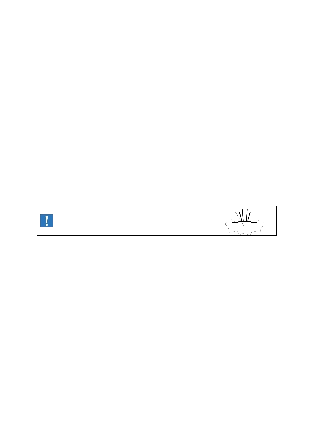
The following must not be used for cleaning:
- Sharp, hard or pointed objects
- Water or steam jet appliances
- Compressed air
- Hazardous and solvent-containing materials
- Cleaning agents that may attack the materials used
8.2.2 Cleaning instructions
For cleaning purposes we recommend that you use warm water with approved cleaning agents for the
respective application, and a soft, lint-free cloth. Once every week the coil shaft should be thoroughly
cleaned, removing any dirt accumulations and deposits. After cleaning wipe up any remaining drops of
water with a dry, non-fibrous cloth until the coil shaft is dry. From time to time apply oil to the stainless
steel framework (e.g. Nirostol 55 cleaning and maintenance oil which meets food industry standards).
8.2.3 Care advice for stainless steel
Only high-quality stainless steel is used in the systems. To prevent rust on the high-grade steel parts
do not use substances containing chloride (e.g. cleaning or disinfecting products) or operate the machine in an atmosphere containing chloride. If this is unavoidable the steel parts must be thoroughly
rubbed down immediately afterwards with cleaning oil e.g. Nirostol 55 cleaning and maintenance oil
(which meets food industry standards).
Important information for stainless steel models
Stainless steel models are extremely weatherproof and are therefore able to withstand most environmental conditions.
However, even stainless steel can be susceptible to a slight film of rust.
These deposits are caused by contact corrosion and can be removed by following the instructions below:
- Use a stainless steel cleaner: in principle any stainless steel cleaner may be used. Please ensure
you read the instructions prior to use.
- Use only cleaning agents that are halogen-free (i.e. without chlorides and fluorides), and salt and
hydrofluoric acid free.
- After each cleaning rinse the machine thoroughly with tap water
- Do not use the following: non-alloy materials or substances, abrasive cloths, cleaning agents containing salt or hydrofluoric acid, chrome, silver or brass cleaners.
54

9. Spare parts
Spare parts and wearing parts must always be obtained from the manufacturer of from a
supplier that is certified by the manufacturer.
3
2
16
9
15
1
20
18
4
5
7
12
6
8
11
13
10
19
17
14
21
9 Spare parts
If you should have any questions please state equipment type and serial number!
9.1 Spare parts view
55

9. Spare parts
Item
No.
Part
Part No.
Material
Art. No.
Sp/Con
1
Electronics housing PRIMUS+
Z0065803
77080254
Sp
2
Cable threaded joint MS-M 20x1.5
33001012
Sp
3
Cable threaded joint MS-M 16x1.5
33001010
Sp
4
Nut 50220 M for cable threaded joint
33001004
Sp
5
Nut 50216 M for cable threaded joint
33001002
Sp
6
Distance bolt M4x20
31160822
Sp
7
Distance bolt M4x10
31160820
Sp
8
Bush
77101378
Sp
9
Hexagon nut M4
31160908
Sp
10
Wall mount for control cabinet
(accessory)
08006717
Sp
11
Distance bolt M4x15
08023239
Sp
12
IO electronics board PRIMUS+
77103219
Sp
13
Membrane keypad PRIMUS+ Sesotec
77100328
Sp
13
Membrane keypad PRIMUS+ Neutral
77100326
Sp
14
Display PRIMUS+
33015460
Sp
15
CU electronics board PRIMUS+
33015446
Sp
16
AC/DC converter (option)
33013134
Sp
17
Hexagon screw M8x20
15090400
Sp
18
Screw plug M20x1.5
33001018
Sp
19
Screw plug M16x1.5
33001016
Sp
20
Memory module (data memory)
77100949
Sp
21
Hexagon nut M8x8
15083200
Sp
9.2 Spare parts list
*Sp/Con = Spare part / Consumable
56

10. Shipping, preservation, waste disposal, transport, storage
1.
Choose packing that is suitable for the type and size of unit, taking into account
whether the shipment is for export by sea or airfreight, or for national or international
road transport The packing material must protect the goods from all damage under
normal transport conditions.
2.
Depending on the size, weight and nature of the goods packing in cardboard boxes,
boxed pallets etc is only suitable for road transport.
Use reinforced card, corrugated cardboard, blister packing and shredded paper to fill
and protect the goods.
Electrostatic sensitive components (electronic boards, electronic modules, etc.) must
be packed in antistatic foil or foil bags prior to packing! (t h i s i s e ss e nt ia l!)
Stick additional warning labels on the outside of the packaging e.g. "Attention, elec-
tronic equipment, do not drop,” etc. The packing should be sealed with adhesive tape
and, where the weight exceeds 50 kg, additionally with wrapping tape..
2a.
When packing for international road transport use the instructions above (see point
2). Larger and heavier shipments must also be protected as for export in wooden
crates. Care must be taken to ensure that the goods inside the packing are protected
against corrosion.
Any parts that will corrode easily must be wrapped in oil paper or corrosion-protective
foil. Care must be taken to prevent the components moving around within the packaging.
2b.
International air freight shipments must be packed in wooden crates or on export paltainers.
Care must be taken that the goods are secure and well-protected inside the packing.
Any parts liable to corrode must be wrapped in oil paper, protective foil or sprayed
with anti-corrosion spray.
2c.
Sea-freight must be packed in seaworthy export crates. These crates can be obtained
from specialist suppliers.
The crates must be lined with oil paper to make them resistant to sea water and prevent corrosion. In addition the goods must be protected against corrosion by use of a
spray or be wrapping in protective foil.
Care must be taken to ensure that the goods cannot move around inside the crate.
After packing the sea-freight crates must be properly closed.
The sea crates must also be fastened externally with securing tapes.
During loading care must be taken not to damage the external packaging.
The carrier must certify that the shipment has been accepted and loaded correctly by
detailing this on the bill of lading, loading list etc.
3.
Waste disposal: Observe the national waste disposal regulations.
10 Shipping, preservation, waste disposal, transport, storage
10.1 Shipping, preservation, waste disposal
57

10. Shipping, preservation, waste disposal, transport, storage
In order to avoid injury or damage to the unit it must be handled properly. In addition to
following the instructions below, general health and safety good practice and specific
accident prevention guidelines should be observed.
For correct handling and storage comply with the following symbols:
Protect against moisture
Careful: glass
Up
Centre of gravity
Do not compress the side walls of the unit or any attached parts by pulling obliquely on
ropes or chains.
Only remove handling safeguards once all installation work has been completed.
When handling in a loading area make sure the unit cannot topple over or slip.
Damage caused during transportation must always be reported to the manufacturer.
If possible the unit should be stored in a closed room until final installation.
If the unit is stored in the open it must be covered over with tarpaulins and open under-
neath to allow condensation to drain off.
Avoid any higher temperature fluctuations. It is possible that condensed water that has
formed in the packing cannot properly drain and may corrode equipment surfaces. If a
formation of condensed water cannot be avoided, suitable desiccants e.g. in the form
of bags must be placed in the packing.
If the unit has been packed for transportation by sea the packaging must not be dam-
aged or opened during transit and storage.
For storage temperature and permissible air humidity please refer to the technical data
sheet.
For correct storage comply with all storage and handling symbols:
Protect against moisture
Careful: glass
Up
10.2 Transport
10.3 Storage
58

11. Annex
11 Annex
EC DECLARATION OF CONFORMITY
Technical data sheet
Accessories:
UL/CSA certificate
59
 Loading...