

Sesamo Puma Millenium Installation Instruction

Automatic Operator for swinging doors
INSTALLATION INSTRUCTION
2

Installation Instruction
PIUMA MILLENNIUM
3
Index
Technical specifications ...................................................................................... page 5
Automatism installation preparation.................................................................... page 5
Automatism description ...................................................................................... page 5
Sizes and dimensions ........................................................................................ page 6
Automatism assembly ........................................................................................ page 7
Adjustment of the stop (Optional) ...................................................................... page 12
Final operations .................................................................................................. page 13
Power connections .............................................................................................. page 13
MILLENNIUM electronic board............................................................................ page 13
Electrical connections.......................................................................................... page 14
Left side electronic board connections .............................................................. page 14
Right side electronic board connections ............................................................ page 15
Led functions ...................................................................................................... page 18
Jumper Function.................................................................................................. page 18
Dip-Switch Function ............................................................................................ page 18
Electric Lock selection ........................................................................................ page 19
Selection of the type of arm ................................................................................ page 19
Selection of the door weight .............................................................................. page 19
“Low Power” mode selection .............................................................................. page 20
MultiSlave Selection ............................................................................................ page 20
Battery mode ...................................................................................................... page 21
“First input mode” selection................................................................................ page 21
Number door selection........................................................................................ page 21
Master - Slave Selection (Piuma Doppio only) .................................................. page 22
Synchronised/indipendent door motion (Piuma Doppio only) .......................... page 22
Start up ................................................................................................................ page 22
Error Message Table............................................................................................ page 23
Setting parameter adjustment ............................................................................ page 24
Operating logic .................................................................................................... page 24
Piuma Doppio connection and use .................................................................... page 26
Inter lock connection and use ............................................................................ page 27
SESAMO reserves the right to change the technical specifications of the products, even without notice.
4
Installation Instruction
Thank you for choosing this product. For best automatism
performance, Sesamo recommends you carefully read and
follow the installation and use instructions found in this manual. Installation of this automatism must only be performed
by the professionally qualified personnel for whom this manual is addressed. Any errors during installation may be
harmful to people or things. Packaging material (wood, plastic, cardboard, etc.) should not be scattered in the environment or left within the reach of children as potential sources
of danger. Every installation phase must be performed in
accordance with the regulations in force and following Good
Technique standards. Before beginning installation make
sure that the product is integral and has not been damaged
during transportation or by poor storage conditions. Before
installing the product make sure that each architectural and
structural element of the entrance (girder fastening surfaces,
casings, guide, etc.) is appropriate and sufficiently robust to
be automated. Conduct a careful risk analysis and make
suitable modifications to eliminate conveyance, crushing,
cutting and hazardous areas in general. Do not install the
product in environments where gas, steam or inflammable
fumes are present. The manufacturer is not liable for any
neglect of “good technique” or specific regulations in the
construction of the casing to be motorised and any collapse
of the same. All automatic entrance safety and protection
devices (photocells, active sensors, etc.) must be installed
in accordance with the regulations and directives in force,
with the completed risk analysis, system type, use, traffic,
forces and inertia in play. Pay careful attention to area where
the following may occur: crushing, cutting, conveyance and
any other type of hazard in general applying, if necessary
suitable indications. Indicate the motorised door identification information on every installation. Make sure that the
upstream electrical system is correctly dimensioned and
has all the opportune protections (circuit breakers and
fuses). Only use original spare parts in maintenance and
repairs. Do not tamper or alter devices in the automatism
and all the safety devices in the control panel for any reason.
The manufacturer is not liable if parts within the automatism
are altered or tampered with or if safety devices other than
those indicated by the manufacturer are used in the system.
The automatism installer must provide the automatic
entrance manager with the use manual and all the information required for correct use in automatic and manual
modes (even for electronic locking) and in the event of
emergency.
Pay careful attention to the messages in this manual that are
marked with the hazard symbol. They can either be warnings aimed at avoided potential equipment damage or specific signals of potential hazard to the installer and others.
This device was designed to automate swinging doors. Any
other use is considered contrary to the use foreseen by the
manufacturer who therefore shall not be held liable.
Machine directive
The installer who motorised a door becomes the automatic
door machine manufacturer according to directive 98/37/CE
and must:
• Arrange the Technical Booklet with the documents indicated in attachment V of the Machine Directive and keep
them for at least 10 years.
• Draft the CE declaration of conformity according to
attachment II-A of the machine directive and provide the
use with a copy.
• Apply the CE markings on the motorised door according
to point 1.7.3 of attachment I of the machine directive.
For more information and for assist installers in applying the
specifications of the directives and of European standards
concerning the safe use of motorised gates/doors consult
the guidelines available on internet at the address
www.sesamo.eu
Machine conformity directive
(Directive 98/37 CE, Attachment II, part B)
Manufacturer: SESAMO S.r.l.
Address: Str. Gabannone 8/10 - 15030
Terruggia - AL
Declares that the product PIUMA MILLENNIUM
• Is built to be incorporated in a machine or to be assembled with other machinery to build a machine considered
by Directive 98/37 CE, as modified;
• Therefore it is not fully compliant to the dispositions of
this Directive since it is not yet assembled with other
components.
• It is in conformity to the following other CE directives:
89/336/CEE Electro-magnetic compatibility and further
modifications 2006/95CE Low Voltage and further modifications and also declares that the machinery cannot be
used until the machine it is incorporated in or is a component of has been identified and its conformity to
Directive 98/37 CE conditions and national legislation
declared.
Terruggia, 21/07/2007
Aldo Amerio
( Administrator )
PIUMA MILLENNIUM
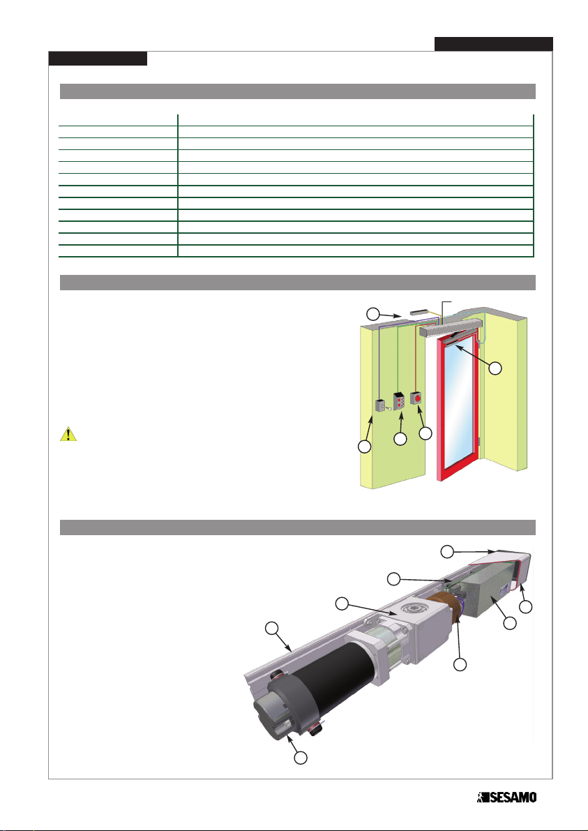
Technical specifications
Automatism installation preparation
The automatism is prepared to work in different accessory and peripheral configurations. According to the selected configuration, arrange
the cables necessary for wiring all the peripherals. Fig.1 shows an
example of complete installation including:
A. Entry Radar
B. Active safety sensor
C. Safety closing device
D. Logic selection selector
E. Opening button at exit
WARNING
If two single Piuma automatisms are used to move a two-doors entrance, the two automatisms must be connected by a shielded cable with
4 0.22mm wires as indicated on page 26.
Automatism description
The PIUMA Millennium automatism (Fig.2) is
essentially made up of:
A. Extruded aluminium alloy fastening base
B. Extruded aluminium alloy cover
C. Aluminium end sides (Flat steel end sides
option)
D. Gear motor unit
E. SESAMO MILLENNIUM Electronic control
panel
F. Transformer
G. Encoder unit
H. Emergency battery (24V 0,8Ah)
For a two-doors entrance, two automatisms
can be ordered in a single transom box
(Piuma Doppio) with custom length (minimum
1600 mm).
Installation Instruction
5
Fig. 1
Fig. 2
PIUMA MILLENNIUM
Power supply 230V ac 50 Hz
Nominal power 60 W
Nominal motor torque 23 Nm
External device power 12Vdc – 6W
Emergency battery 24 V 0.8 Ah
Max opening angle 100°
Door maximum weight Up to 200 Kg
Door dimensions 700÷1200 mm
Working temperature Box inside from 0°C to+50°C
Anti-crushing Automatic traction restriction in the presence of obstacles
Weight 8,6 kg
Service Continuous (>500 cycles/day, with capacity of 300 cycles/hour for 2 hours)
A
E
D
C
B
230V AC
A
B
D
C
G
F
E
H

6
Installation Instruction
PIUMA MILLENNIUM
Standard End
Sides
Flat End Sides
(opzionali)
Fig. 5
Fixing Holes (Std End Sides)
Fixing Holes (Flat end sides)
Gearmotor axis
Gearmotor axis
AA
AA
AA
AA
Fig. 3
Fig. 4
Sizes and dimension
The Piuma Millennium automatism is available in two configurations: with standard heads in aluminium (L=810 mm) and
with flat heads (optional) in steel (L=
800 mm).

Installation Instruction
PIUMA MILLENNIUM
7
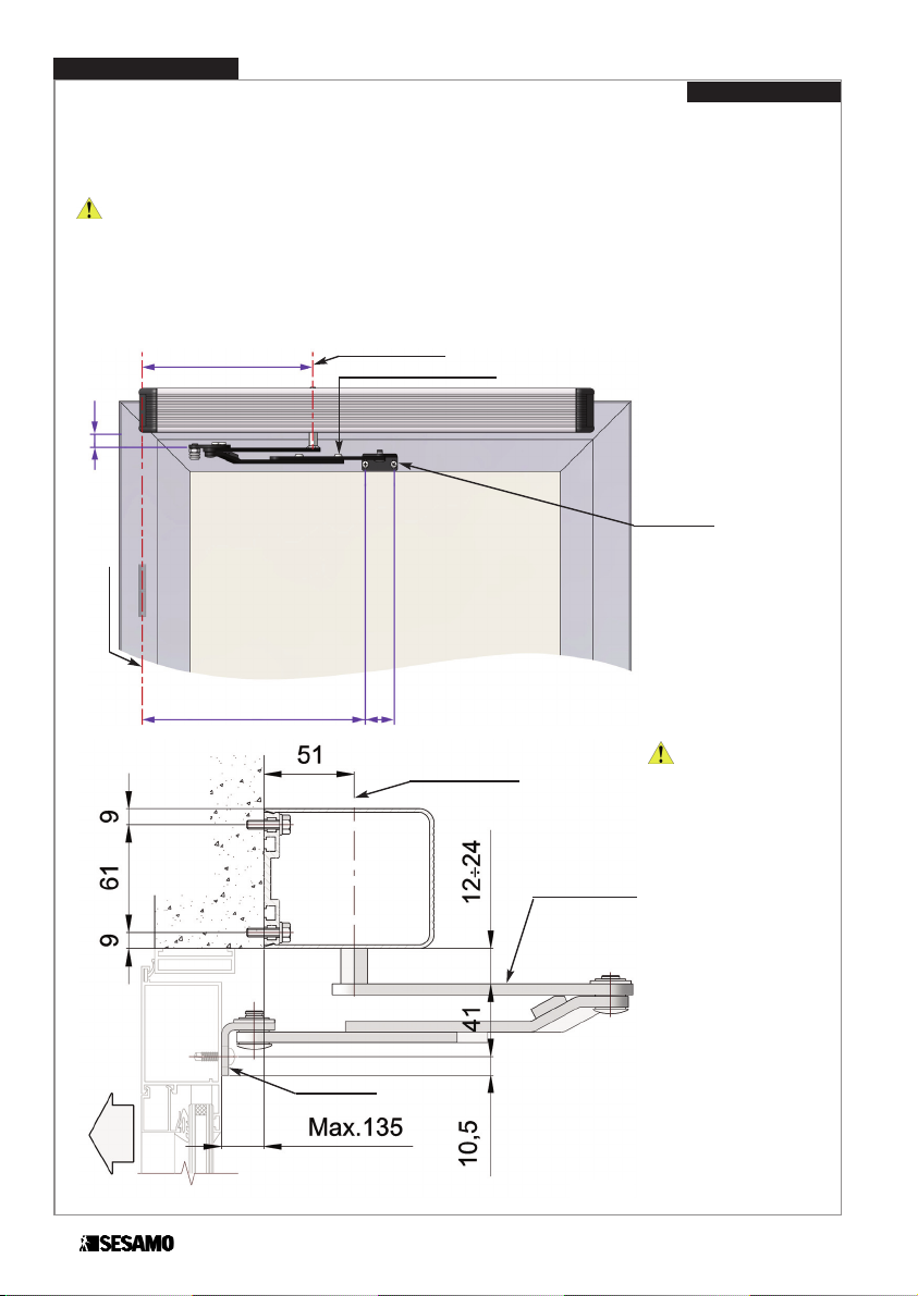
Automatism assembly
WARNING : Before proceeding with the installation, remove the cardboard component positioned underneath the
motor body.
Positioning dimensions (rigid pull arm)
The rigid pull arm is used when the automatism is installed on the swing side of the door .
WARNING
: For a correct positioning, always use the main axis of the door hinges and the operation axis of the
gearmotor as a reference, as shown in Fig.6.
Make certain that the fastening of the holes "A" (Fig. 4 and 5) is particularly
secure.
300
150 600
15÷29
Piuma Millennium
fastening diagram
1 left-hand opening door
Rigid Pull Arm
Standard End Sides
Gearmotor Axis
Hinge axis
Rigid pull arm
Aluminium guide
Fig. 6
The heights of the prepared fastening holes are
shown in Fig. 4 and 5
.
For right-hand opening
doors (anticlockwise direction), the assembly of the
automatism perfectly mirrors the left-hand opening
assembly.
Rigid pull arm
Aluminium guide
Gearmotor Axis
OPENING DIRECTION
Fig. 7
WARNING : The final tighte-
ning of the screws must be performed only after having checked
that the vertical positioning of the
automatism guarantees a good
parallelism between the hinge
axis and the gearmotor axis. For
this purpose, the rigid pull arm
and relative guide must be installed, check that the pin coupling
the arm to the cylindrical slide is
not strained during operation.
An error in the position of the automatism may, in fact, cause the pin
of the rigid arm to oscillate with
respect to the cylindrical slide to a
degree beyond the allowed tolerance, with consequent damage to
one of the automatism parts.
8
Installation Instruction
PIUMA MILLENNIUM
OPENING DIRECTION
Gearmotor Axis
Articulated push
arm
Door Attachment
Fig. 9
Piuma Millennium
Fastening diagram
1 left-hand opening door
Articulated push arm
Standard End Sides
300
12÷24
50380
Hinge axis
Articulated push arm
Door Attachment
Gearmotor Axis
Fig. 8
The heights of the prepared fastening holes are
shown in Fig. 4 and 5.
For right-hand opening
doors (anticlockwise direction), the assembly of the
automatism perfectly mirrors the left-hand opening
assembly.
Positioning dimensions (articulated push arm)
The articulated push arm is used when the automatism is installed on the approach side of the door (the side opposite the
swing side). For left-hand opening doors (door opening with anti-clockwise rotation) position the automation as shown in
Fig. 8 (using the heights shown in Fig. 4 and 5).
WARNING : For a correct positioning, always use the main axis of the door hinges and the operation axis of the gearmotor as a reference, as shown in Fig.8. Make certain that the fastening of the holes "A" (Fig. 4 and 5) is particularly secure.
WARNING : The final
tightening of the screws must
be performed only after
having checked that the positioning of the automatism
and articulated arm guarantees smooth rotation of the
same under the door frame,
maintaining a distance of 12
to 24 mm between the top
part of the articulated push
arm and the lower part of the
automatism cover (Fig. 9).
Installation Instruction
9
PIUMA MILLENNIUM
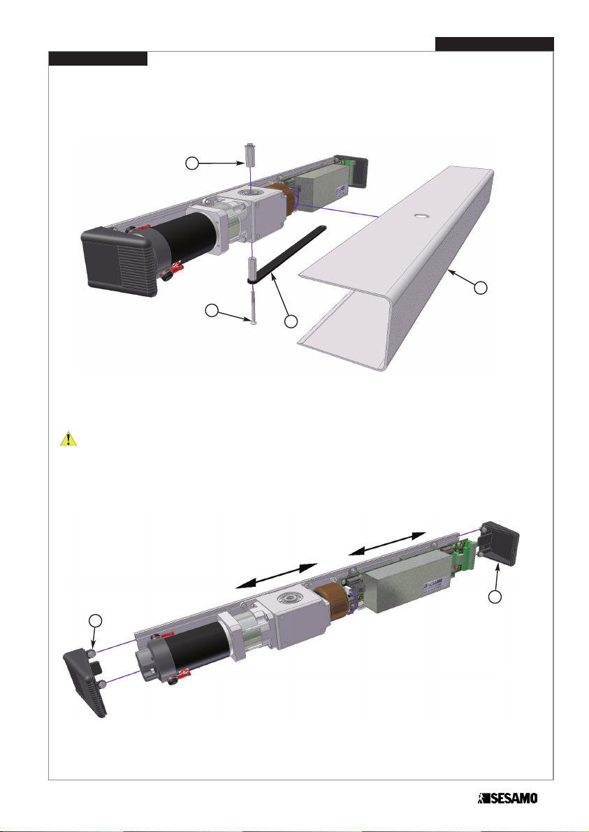
Automatism components shift and removal
Disassemble the push arm (if present) (Fig. 10 Part A) by unscredoor the counter-sunk head screw M6 x 70 (Fig. 10 Part
B). Extract the top hexagonal stop (Fig. 10 Part C). Remove the aluminium cover (Fig. 10 Part D) by pulling it outwards.
To facilitate the fastening of the automatism, it is possible to remove the heads (Fig. 11 Part A) and move or remove the
internal components, if necessary, by operating on the nuts fastening them to the aluminium base.
WARNING: Before loseening component lock screws to move components, measure the distance of the motor from
the head or make marks on the box for correct component positioning at the end of assembly.
Fig. 10
A
Fig. 11
B
C
D
A
A
 Loading...