


Automatic Operator for swinging doors
OPERATING INSTRUCTIONS
PROSWING (m)
PROSWING (M)
Operating instruction
2

3
Index
Technical specifications .................................................................................................. pag. 6
Function Low-energy ...................................................................................................... pag. 6
Warnings for the installer and general safety ................................................................ pag. 7
Recycling and disposal .................................................................................................. pag. 7
Intended use .................................................................................................................. pag. 8
Limit of use .................................................................................................................... pag. 8
Types of arms.................................................................................................................. pag. 9
Arm extensions................................................................................................................ pag. 10
Dimensions...................................................................................................................... pag. 10
Preliminary checks.......................................................................................................... pag.11
Automatism fixing............................................................................................................ pag. 11
Aluminum base holes positioning .................................................................................. pag. 13
Pull arm installation ........................................................................................................ pag. 14
Push arm installation ...................................................................................................... pag. 18
Preliminary checking ...................................................................................................... pag. 21
Wiring power supply ...................................................................................................... pag. 22
Control board Proswing (M) .......................................................................................... pag. 22
Wiring .............................................................................................................................. pag. 23
External peripherals connectors-Input .......................................................................... pag. 24
External peripherals connectors-Output ........................................................................ pag. 25
Dip-switches setting ........................................................................................................ pag.26
Parameters adjustment-display ...................................................................................... pag. 27
Start up............................................................................................................................ pag. 30
Message or errors code.................................................................................................. pag. 31
Operating logics.............................................................................................................. pag. 32
Electric lock selection and setting.................................................................................. pag. 33
PROSWING (M)
3
PROSWING(M)
Operating instruction

4
Operating instruction
PROSWING (M)
Selectors terminal board ................................................................................................ pag. 35
External peripheral power connector(15Vdc) ................................................................ pag. 35
Wiring and use for double Proswing .............................................................................. pag. 36
Inter lock wiring and use ................................................................................................ pag. 39
Installation batteries (OPTIONAL) .................................................................................. pag. 40
Logic switch .................................................................................................................... pag. 42
Connector for PC-Unit connections................................................................................ pag. 42
Delivery modality ............................................................................................................ pag. 42
SESAMO reserves the right to change the technical specifications of the products, even without notice.

Operating instruction
PROSWING (M)
5
Thank you for choosing this product. For best automatism
performance, Sesamo recommends you carefully read and
follow the installation and use instructions found in this
manual. Installation of this automatism must only be performed by the professionally qualified personnel for whom this
manual is addressed. Any errors during installation may be
harmful to people or things. Packaging material (wood, plastic, cardboard, etc.) should not be scattered in the environment or left within the reach of children as potential sources
of danger. Every installation phase must be performed in
accordance with the regulations in force and following Good
Technique standards. Before beginning installation make
sure that the product is integral and has not been damaged
during transportation or by poor storage conditions. Before
installing the product make sure that each architectural and
structural element of the entrance (girder fastening surfaces,
casings, guide, etc.) is appropriate and sufficiently robust to
be automated. Conduct a careful risk analysis and make suitable modifications to eliminate conveyance, crushing, cutting and hazardous areas in general. Do not install the product in environments where gas, steam or inflammable
fumes are present. The manufacturer is not liable for any
neglect of “good technique” or specific regulations in the construction of the casing to be motorised and any collapse of
the same. All automatic entrance safety and protection devices (photocells, active sensors, etc.) must be installed in
accordance with the regulations and directives in force, with
the completed risk analysis, system type, use, traffic, forces
and inertia in play. Pay careful attention to area where the
following may occur: crushing, cutting, conveyance and any
other type of hazard in general applying, if necessary suitable indications. Indicate the motorised door identification
information on every installation. Make sure that the
upstream electrical system is correctly dimensioned and has
all the opportune protections (circuit breakers and fuses).
Only use original spare parts in maintenance and repairs. Do
not tamper or alter devices in the automatism and all the
safety devices in the control panel for any reason. The
manufacturer is not liable if parts within the automatism are
altered or tampered with or if safety devices other than those
indicated by the manufacturer are used in the system. The
automatism installer must provide the automatic entrance
manager with the use manual and all the information required for correct use in automatic and manual modes (even for
electronic locking) and in the event of emergency.
Pay careful attention to the messages in this manual that are
marked with the hazard symbol. They can either be warnings
aimed at avoided potential equipment damage or specific
signals of potential hazard to the installer and others.
This device was designed to automate pedestrian swinging
doors. Any other use is considered contrary to the use foreseen by the manufacturer who therefore shall not be held liable.
Machine directive
The installer who motorised a door becomes the automatic
door machine manufacturer according to directive
2006/42/CE and must:
• Arrange the Technical Booklet with the documents indicated in attachment VII of the Machine Directive and keep them
for at least 10 years.
• Draft the CE declaration of conformity according to attachment II-A of the machine directive and provide the use with a
copy.
• Apply the CE markings on the motorised door according to
point 1.7.3 of attachment I of the machine directive.
For more information and for assist installers in applying the
specifications of the directives and of European standards
concerning the safe use of motorised gates/doors consult
the guidelines available on internet at the address
www.sesamo.eu
DECLARATION OF INCORPORATION
(Directive 2006/42/CE, Annex II, part B)
Manufacturer: SESAMO S.R.L.
Address: Str. Gabannone 8/10 -
15030 Terruggia – AL ITALY
Declares that the product PROSWING (m)
- is built to be incorporated in a machine to build a machine
considered by Directive 2006/42/CE
- is conform to the essential safety requirements set out in
annex I of the directive with the exclusion of the following
points: 1.2.4.3, 1.2.4.4, 1.3.4, 1.3.5, 1.3.7, 1.3.8.2, 1.4, 1.5.3,
1.5.7, 1.5.14, 1.5.15, 1.5.16
- is conform to the following other CE directives:
2004/108/CE Electromagnetic Compatibility, 2006/95/CE
Low Voltage
- have been applied the following harmonized norms:
EN 60335 - 1 EN 61000 - 6 - 2
EN 50366 EN 61000 - 6 - 3
And also declares that:
- relevant technical documentation has been fulfilled in
accordance with part B of annex VII of the Directive; this
documentation, or part of it, will be transmitted, by post or
mail, in response to a reasonable request by the national
authorities
- the person authorized to compile the relevant technical
documentation is: SESAMO SRL, Strada Gabannone, 8/10 15030 Terruggia (AL) - Italy
- the partly completed machinery must not be put into service until the final machinery into which it is to be incorporated
has been declared in conformity with the relevant provisions
of the Machinery Directive 2006/42/CE
SESAMO S.R.L. Director
February 2012 ALDO AMERIO
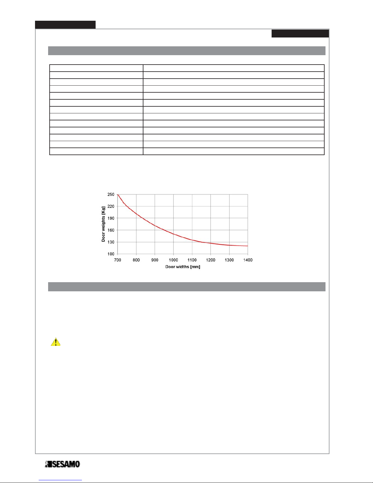
Technical specifications
In the diagram there is the max door weights related with the door widths:
Function LOW-ENERGY
PROSWING (M) can be set in the order to meet requirements of Low-Energy application according DIN 18650 or BS 7036-
4.
In Low-Energy mode safety is ensured by:
- low speed;
- reduced dynamic/static force.
ATTENTION: Installation of safety sensors monitoring opening and/or closing path is an option to consider after risk
assessment evaluation.
Power supply 230V +/- 10% ac 50 Hz
Nominal power 85 W
Nominal motor torque 45 Nm
External device power 12Vdc – 12W max
Emergency battery power 24V 1,3 Ah
Opening time 3 ÷ 6 sec (70 °/s ÷ 20 °/s)
Closing time 4 ÷ 15 sec (40 °/s ÷ 10 °/s)
Max opening angle
110°
Wing dimension 700 ÷ 1400 mm
Working temperature Inside automatsm from -10°C to +50°C
Anti-crushing Automatic traction restriction in presence of obstacles
Weight 10,5 kg approx
Service Intensive
PROSWING (M)
Operating instruction
6
Warnings for the installer and general safety
1) It is important for the safety of the people installing the automatism according to the regulations. A wrong installation or
use of the product might lead to serious damages to people.
2) Read carafully the operating instructions before installing the product.
3) Store the operating instructions for future reference.
4) This automatism has been designed and built exclusively for the use specified in this documentation. Any different use not
stated herain could affect the integrity of the product and/or represent danger situation.
5) SESAMO declines any responsabilty from misuse or different use from which it was intended.
6) Do not install the product in explosive enviroment: the presence of flamabel gases or fumes is a serious safety hazard.
7) SESAMO is not responsible for the failure to comply with the Good Technical construction procedure of the door to be automated, as well as deformations that may occur to the door when using the same.
8) Before making any service to the product, take off power supply.
9) Instal a bi-polar switch to cut off power supply.
10) Verify functionality of ground wiring.
11) Safety devices (norm EN 12978) protect possible dangerous areas from mechanical risks during movement, as. anticrashing, conveying, shearing.
12) For mainteinance use only genuine SESAMO spare parts.
13) Do not modify components that belongs to the whole automatism.
14) The installer must supply end user all the informations in case of manual operating in emergency.
15) End user shall refrain from any attemp to repair or direct intervenction and ask only to qualified personnel.
16) Installation must be done only from a qualified personnel and in full compliance with regulations.
17) Everything not including in this operating instruction manual is not allowed.
18) This operating instructions manual is only intended for qualified personnel.
Recycling and disposal
RECYCLING OF THE AUTOMATISM AND PACKAGING
This product is built with different materials. The major parts (aluminium, plastic, iron,wires) are solid urban waste. They can be
recycled through collection and disposal in authorized centers.
Other components (control boards, etc.) may contain pollutants. They need to be removed and hand over to companies autho-
rized to recover and dispose them.
The packaging (paperboard, plastics etc.) are solid urban waste and they can be disposed of without any problem, simply per-
forming waste collection for recycling.
Before proceding it is always reccomendr to verify local specific norm for disposal.
PLEASE RECYCLE!
7
PROSWING (M)
Operating instruction

Intended use
The device must be used to automate pedestrian swinging door only.
This device is an electro mechanical system that allow to open and close a swinging door using a trasmission arm.
Door is closed through a motor/spring system or only spring while power is off.
Programmable electronic control board allows correct functionning depending on the type of installation.
Limit of use
ATTENTION: Do not exceed door weight and width as shown in the diagram in “technical specification” paragraph.
To each type of arm correspond a different type of jamb dimension: do not exceed this value (see Paragraph “arm installation”).
This device is intended only for swinging pedestrian door, dry and inside use.
SESAMO shall not be held liable for any other use contrary to the use foreseen.
RIGID PULL ARM ARTICULATED PUSH ARM
MAX JAMB DEPTH [A] -50 ÷ +100 mm
0 ÷ 300 mm
(depending on the type of arm:
standard or long)
DISTANCE FROM THE ALU-
MINIUM BASE AND DOOR
BRACKET [B]
67 ÷ 127 mm 35 ÷ 95 mm
A
B
-50
+100
B
A
300
PROSWING (M)
Operating instruction
8
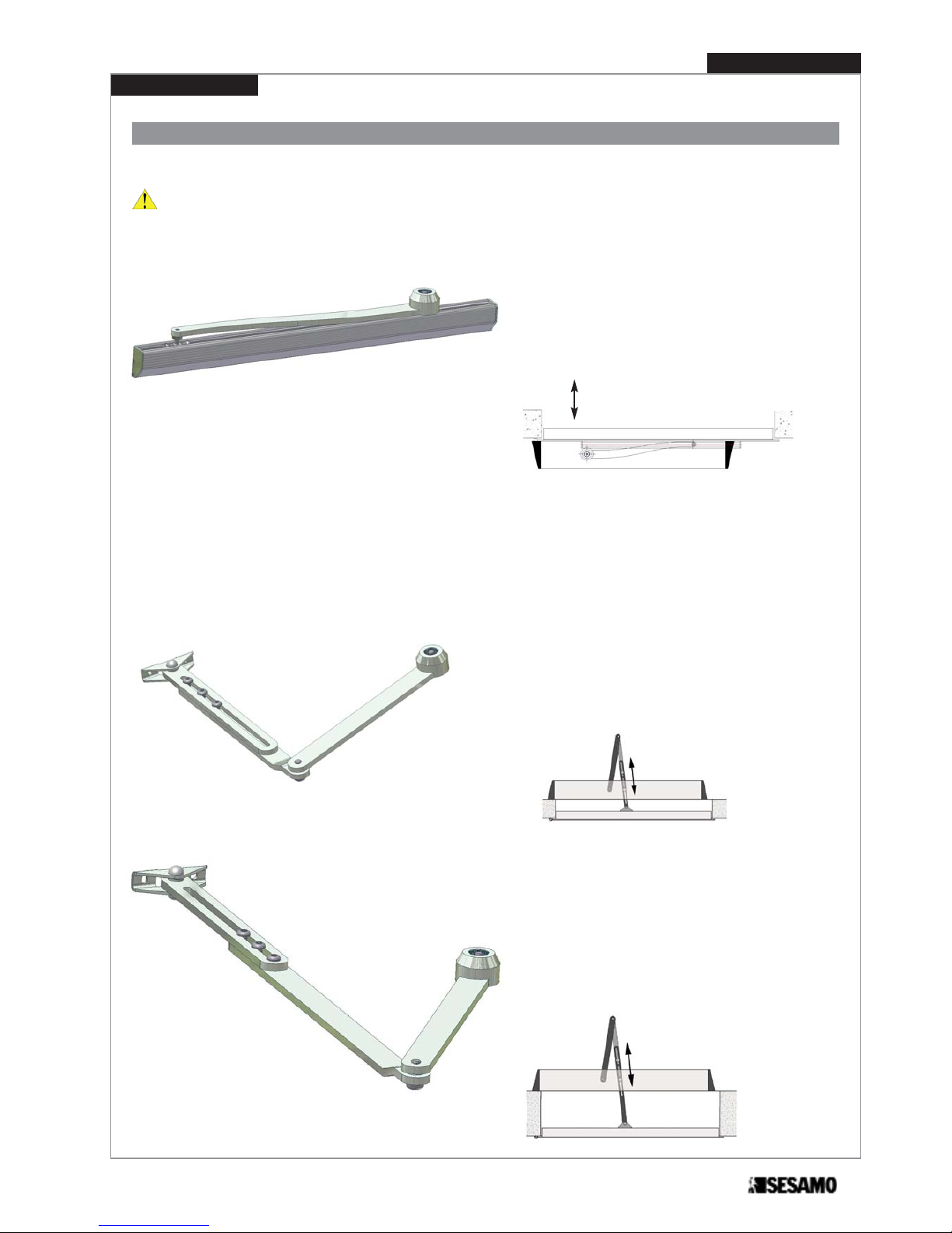
Types of arm
ATTENTION: For proper positionning, please refer to the paragraph “Arm Installation”.
PULL ARM
The pulling arm can be fitted:
- PULL (it is used when the automatism is installed
on the same side of the door opening).
STANDARD PUSH ARM
The pushing arm can be fitted :
- PUSH (it is used when the automatism is installed
on the opposite side of the door opening).
LONG PUSH ARM
The long push arm can be fitted:
- PUSH (it is used when the automatism is installed
in the opposite side of the door opening).
jamb depth = 0 ÷ 150 mm
jamb depth = 150 ÷ 300 mm
jamb depth = -50 ÷ 100 mm
Fig. 1
Fig. 2
Fig. 3
9
PROSWING (M)
Operating instruction
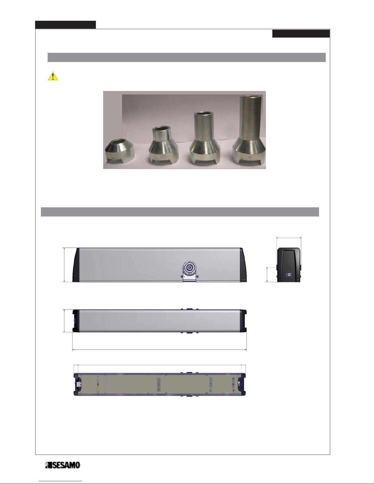
Dimensions
Arm extensions
ATTENTION: For a correct positionning refer to “arm installation” paragraph.
L=50 mm
L=70 mm
L=90 mm
Fig. 4
L=30 mm
(standard)
Fig. 5
56
130
664
86
94
17
630
17
PROSWING (M)
Operating instruction
10
Preliminary checks
Before installing the automatism please check:
- verify the installation does not create dangerous situations;
- prearrange proper pipes and counduits for the wires, granting the protection of the same against mechanical damages;
- the surface where fixing the automatism has to be resistant. Use screws, bolts, etc. adequate to the type of surface;
- the structure of the door has to be strong to hold the weight of the automatism as well the hinges, also check to not
have friction between fixed and mobile parts;
- use proper equipment and tools to install in security and in accordance with the regulations.
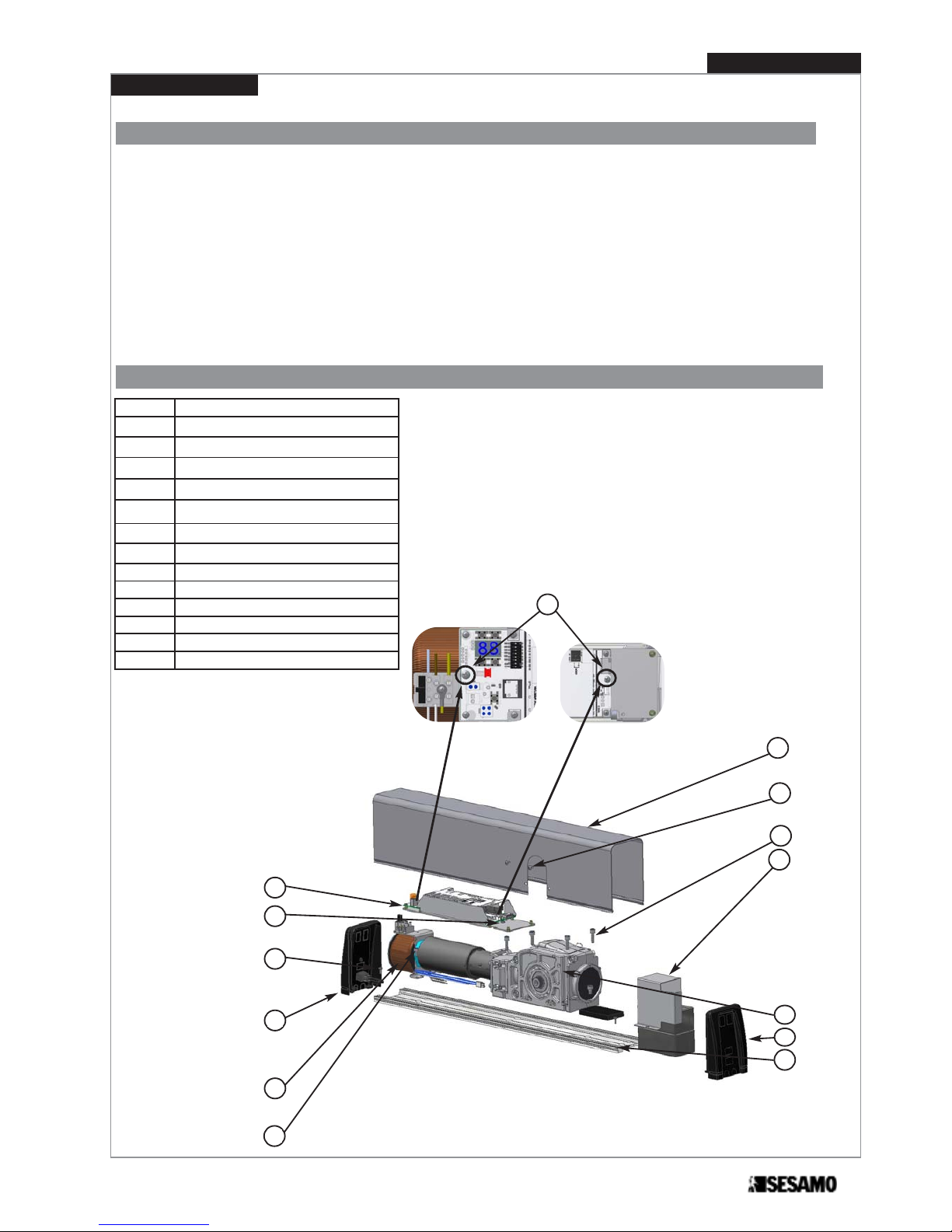
Automatism Fixing
REF. DESCRIPTION
A Cover fixing screws
B Aluminum cover
C Control board fixing screws
D Control board
E Gear motor fixing screws
F Gear motor
G Transformer fixing screws
H Transformer
I End caps fixing screws
L End cap opposite transformer side
M End cap transformer side
N Aluminum base
O
Battery group (OPTIONAL)
C
B
C
A
I
M
H
G
E
L
O
F
N
D
Fig. 6
11
PROSWING (M)
Operating instruction
To fix automatism proceed as follows:
1- remove cover (Fig.6 part.B);
2- disconnect all wiring (encoder, switches, transformer, motor) on control board;
3- unscrew the 2 screws (Fig.6 part.C) and remove control board with its support (screws remain between control board and
support);
4- unscrew the 2 screws (Fig.6 part.G) and remove transform;
5- unscrew the 4 screws (Fig.6 part.E) and remove gear motor;
6- unscrew screws (Fig.6 part.I)and remove end caps (Fig.6 part.M ed L);
7- fix aluminium base (Fig.6 part.N) to thre structure following instructions of the following paragraphs, dipending on arm type;
8- reassemble all components but end caps and aluminium cover.
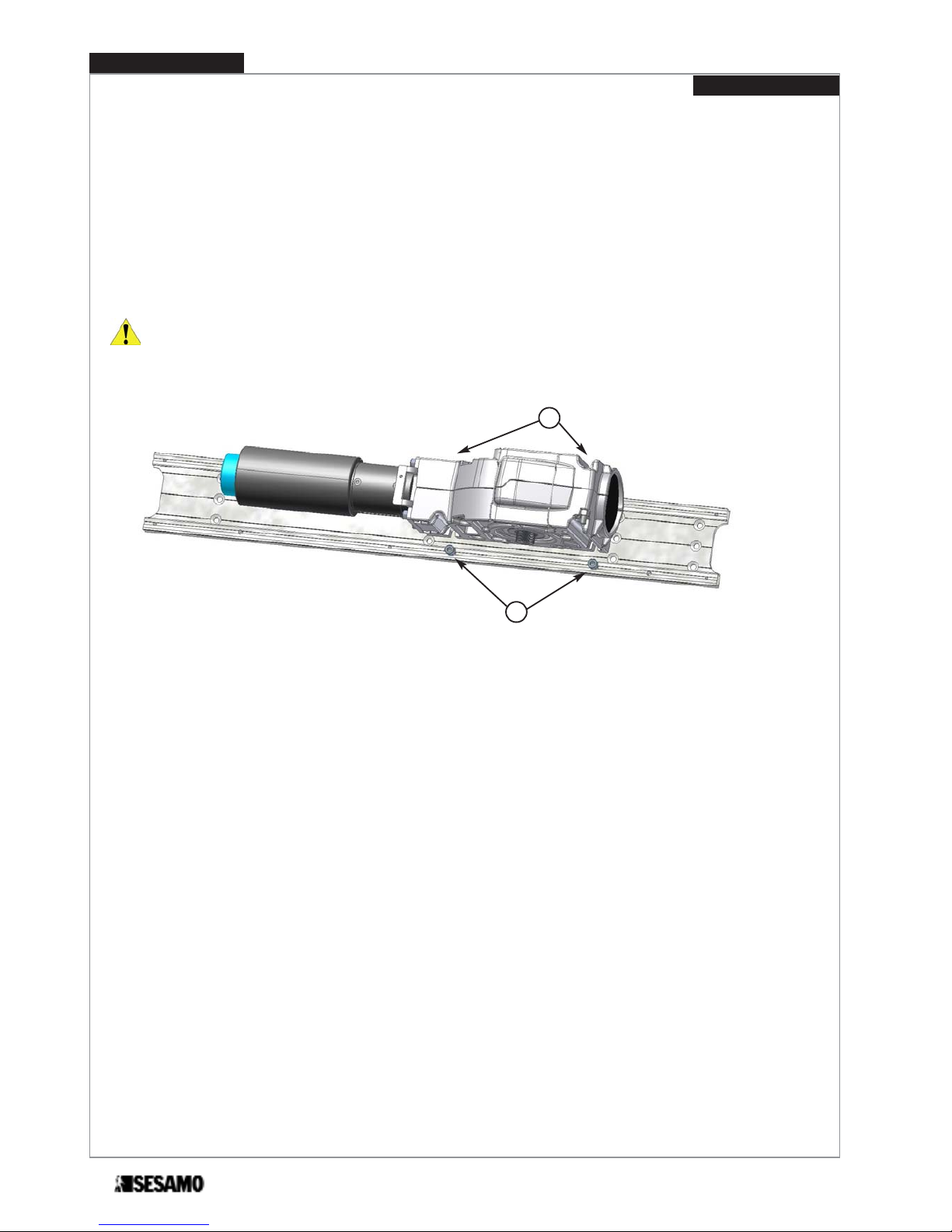
ATTENTION: to make easier reassembling gear motor, partially screw the screws (Fig. 7 part. E), then lean gear motor
on to them. Insert screws (Fig. 7 part. F).
Tight all screws paying attention that gear motor axis is perpendicular to the door top edge.
Fig. 7
E
F
PROSWING (M)
Operating instruction
12
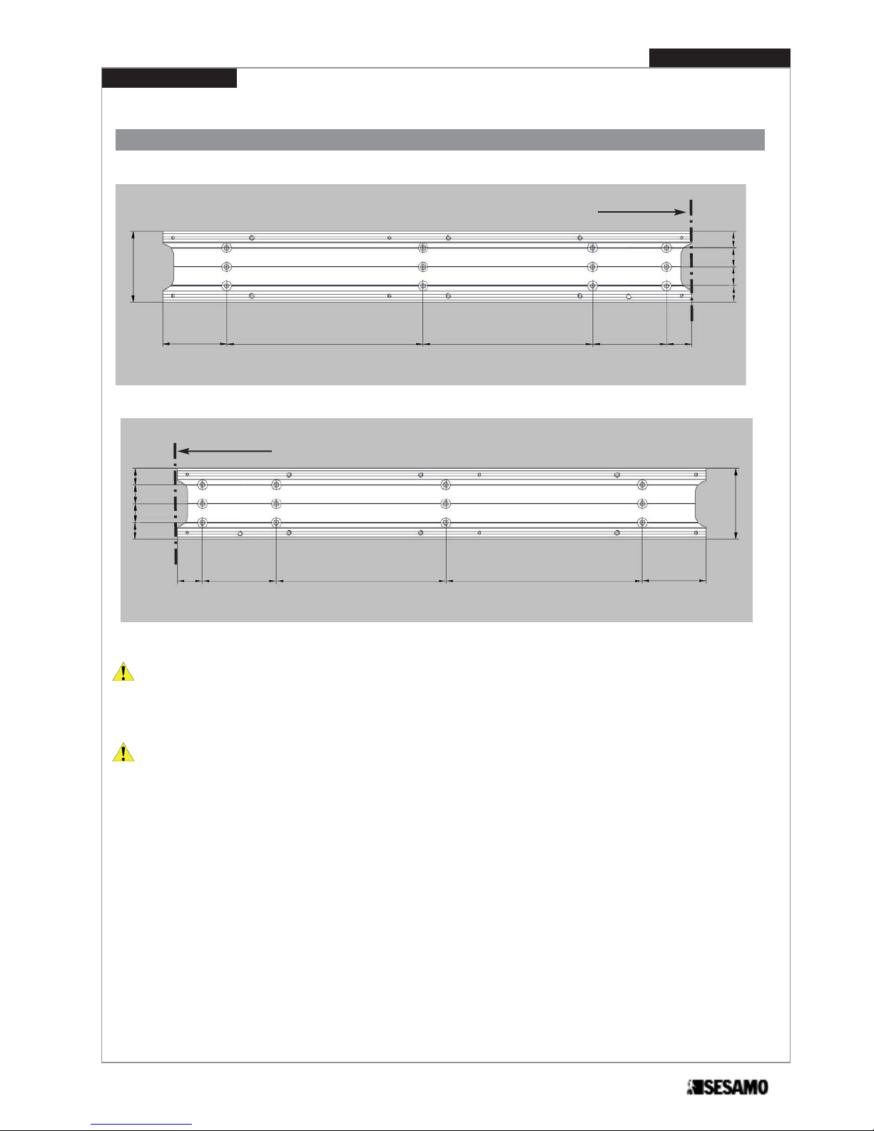
Drilling holes according to the type of screws chosen and fix the base only after verifying the “Positioning dimensions”
listed in the paragraph concerning the type of arm selected.
Fig. 8
With double automatism prearrange the conncetion (wiring) between the two single automatisms.
84
76
88
202
234 30
Aluminum base holes positioning
19,5
19,5
22,5
22,5
Fig. 9
84
76
88
202
23430
19,5
19,5
22,5
22,5
hinge axis
hinge axis
13
PROSWING (M)
Operating instruction
14
Operating instruction
PROSWING (M)
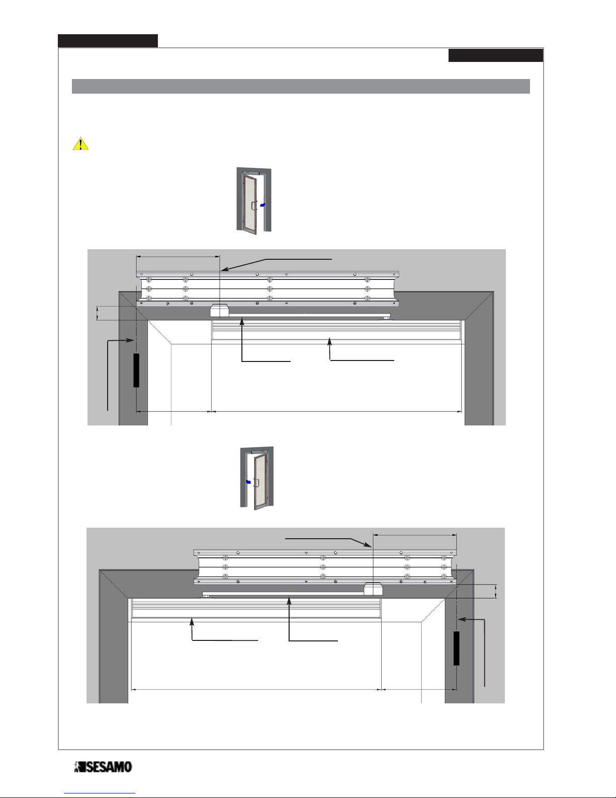
Pull arm installation
Pull arm positioning
Pull arm has to be used when automatism is installed on the same side of door opening.
ATTENTION: For a correct positionning always refer to the hinge axis and gear motor axis, as shown in Fig.10 e 11.
Door opening RIGHT (see Fig. 11)
Door opening LEFT (see Fig. 10)
Fig.10
Hinge axis
Pull arm
Sliding guide
Gear motor axis
600
180
C
200
Fig. 11
AHinge axis
Pull arm
Sliding guide
600
180
C
200
Gear motor axis

Operating instruction
PROSWING (M)
15
Sliding guide
Gear motor axis
OPENING
DIRECTION
56
C
ATTENTION: final tightening
of the screws must be performed
only after checking that vertical
positioning of the automatism
allow a good parallelism between
hinge axis and gear motor axis.
Therefore, after fixing the pulling
arm and its guide, the coupling
bolt of the arm with the cylindric
skid have not to create force in
opening/closing cycle.
A positioning error of the automatism might create bending between the bolt of the pulling arm
and the cylindric skid more than
the allowed tolerance, damage
parts of the automatism.
32
ARM EXTENSION DIMENSION “C”
Arm extension standard 35
Arm extension (L= 50 mm) 55
Arm extension (L= 70 mm) 75
Arm extension (L= 90 mm) 95
Upper door level
Fig. 12
Jamb depth=-100 mm
Within jamb depth maximum opening angle is proportionally reduced.
Jamb depth=+50 mm

Sliding guide installation
1- Unthread profile (Fig.13 Part.I) and drill 4 holes on the “V” mark on guide profile.
2- Fix guide profile horizontally to the door following dimensions shown in Fig.12.
P
O
I
Fig. 13
4- Insert washer (Fig.14 part.B) and screw (Fig.14 part.C) into arm extension (Fig.14 part.A).
5- Insert arm (Fig.14 part.D) in the arm extension slot, and tight screws (Fig.14 part.E)..
A
B
C
D
E
Fig. 14
PROSWING (M)
Operating instruction
16

6- Insert arm extension (Fig.14 part.A) on the shaft and tight screw (Fig.14 part.C) until arm extension is well fixed to gear motor
shaft.
7- Insert skid (Fig.15 part.G) inside the guide (Fig.15 part.O) and slightly open door.
8- Rotate arm until reaching skid (Fig 15 part. F).
9- Screw skid shaft (Fig.15 part.F) into the arm (Fig.15 part.Q).
10-Insert guide cover profile (Fig.15 part. I)
11-Insert right end cap (Fig.15 part.M) and the left end cap (Fig.15 part.N) onto the guide with their screws (Fig.15 part.L).
I
F
L
N
O
P
M
Fig. 15
Q
Verify the dimension about 15 mm (Fig. 16)
Fig. 16
15 mm
17
PROSWING (M)
Operating instruction

Diagram for door opening RIGHT (Fig. 17)
Hinge axis
Door bracket
Motor reducer axis
200
Diagram for door opening LEFT (Fig. 18)
Fig. 17
Hinge axis
Door bracket
Motor reducer axis
200
Fig. 18
Push arm installation
Push arm is used when automatism is installed on the opposite side of door opening.
ATTENTION: For a correct positionning always refer to the hinge axis and gear motor axis, as shown in Fig.17 e 18.
PROSWING(M)
Operating instruction
18

Operating instruction
PROSWING(M)
19
272.5
55
Hinge axis
Door bracket
Fig. 19
35
ARM EXTENSION DIMENSION “E”
Arm extension standard 8
Arm extension (L= 50 mm) 28
Arm extension (L= 70 mm) 48
Arm extension (L= 90 mm) 68
Fig. 20
OPENING
DIRECTION
Push arm
Door bracket
56
Motor axis
Jamb lower edge
ATTENTION: final tightening of the screws must be perfored only after checking arm can easily rotate under door
jamb (Fig.20).
E
Increasing jamb depth, maximum opening angle is proportionally reduced.
25
Jamb depth=0÷300 mm

For PUSH ARM proceed as follows:
1- Insert washer (Fig.21 part.B) and screw (Fig.21 part.C) into arm extension (Fig.21 part.A).
2- Insert arm (Fig.21 part.D) in the arm extension slot, as show in Fig. 21 and tighten screws (Fig.24 part.E).
3- Unscrew screws M8 x 16 (Fig.21 part.G).
4- Fix door bracket (Fig.24 part.F) to the door following dimension shown in Fig. 19 e 20.
5- Insert arm extension (Fig.21 part.A) into gear motor shaft.
6- Tight screw (Fig.21 part.C) until arm extension (part 1) is well fixed to gear motor shaft.
7- Keeping door closed, rotate arm as show in Fig. 22 and tight screws M8 x 16 (Fig. 21 Part. G).
Fig. 21
A
B
C
E
D
F
G
Fig. 22
Fix PUSH ARM to the door
PROSWING(M)
Operating instruction
20

Preliminary checking
Before electrical wiring, check as follows:
• Remove carefully dust or any other residual of the installation
• Verify automatism being well fixed
• Verify all screws well tighten
• Verify all wiring well fixed and not near moving parts
• Verify arm well fixed to door.
21
PROSWING(M)
Operating instruction

Wiring power supply
ATTENTION: Wiring the connectors of the control panel or external peripheral connections must occur in absence of
power supply in order to avoid irreversible damages of the electronic device.
ATTENTION: before performing the following operation make sure the power supply is OFF. Before starting the
automatism, check and perform as paragraph “Start up”.
Bring the power supply cable into the automatism paying
particular attention to not damage the cable against any
metal edges. Connect power supply and groud cable on
their connectors as shown in (Fig. 23)
ATTENTION: Never invert power supply cable and
ground cable.
Power suppply must be isolatable from the general panel
with a bi-polar switch with minimum contact opening equal
to 3 mm (not supplied).
Control board PROSWING (M)
Fig. 24 shows the main electronic components connection of the control board:
230V AC
Fig. 23
Fig. 24
Base or advanced
selector connector
Motor
connector
Electric lock
connector
Encoder
connector
Dip Switchs
PC Connector
output
Switch Auto/Man/Stop
open connector
ON-OFF
switch con-
nector
Transformer
connector
Display
and but-
ton
External peripherals
connector input
External peripherals
connector output
Power supply
Sensosi/Accessories
Expansion
connector
Battery
connector
PROSWING(M)
Operating instruction
22

Operating instruction
PROSWING(M)
23
Fig. 25
Connect the following terminal boards:
- logic switch [Fig. 25 part.A];
- ON-OFF switch [Fig. 25 part.B];
- transformer [Fig. 25 part.C];
- motor [Fig. 26 part.D];
- encoder [Fig. 26 part.E].
Wiring
B
C
A
Fig. 26
D
E

External peripherals connectors - Input
* NO =Normally Open NC =Normally Closed
All the input have to be referred to (COM)
PROSWING(M)
Operating instruction
24
SIGNAL
TYPE
DEFAULT*
DESCRIPTION FUNCTION
KEY NC Lock contact. Lock devices can be
connected such as electronic key,
key selector, proximity reader, etc.
If the contact opens the unit sends a complete closing
cycle command (from any position) From this moment
until the signal is closed the door stays closed and no
external peripheral is detected (including the multi-logics
selector). As soon the signal closes the door opens and
allow again the standard operating.
The signal must be short circuited with COM if no device is connected.
START 1 NO Opening contact. door opening
devices can be connected.
Closing this signal gives the command to open the door. This
signal is only monitored in 2 Radars logic, selectable through
base or advanced selectors (optionals).
START 2 NO Opening contact. door opening
devices can be connected.
Closing this signal gives the command to open the door. This
signal is monitored both in 2 Radars logic both in 1 Radar
logic selectable through base or advanced selectors (optionals).
SAFE OPEN NC Opening safe contact for safety
sensors monitoring opening cycle.
If the door is opening and the contact closes, the control
board gives a stop command immediately. Opening will only
continue after this signal is disactivated.
The signal must be short circuited with COM if no device is connected.
SAFE
CLOSE
NC Closing safe contact for safety sen-
sors monitoring closing cycle.
If the door is closing and the contact opens, the control
board gives an inversion command immediately. Closing will
only continue after this signal is disactivated.
The signal must be short circuited with COM if no devices (internal or external) are connected.
COM Common electrical contacts.
AUX IN 1/2 NA auxiliary input signal that can be
set as follows:
0 -
DDA opening
Command DDA opening (disabled people).
Opens with motor and closes with spring (LOW ENERGY
mode) with minimal idle time of 5 seconds.
1 -
Emergency open
It opens not depending on the existing logic, over takins as
priority also input KEY. It opens door with priority on all
other contacts.
2
- Inter lock with priority
Opens with priority in case of simultaneous command
3
- Inter lock without priority
It doesn’t open in case of simultaneous command
4 -
Feedback Lock released
Micro switch or contact detecting the status of lock released.
5 -
Command lock release
This contact allows to unlock manually the lock without opening door through motor.
6
- Single command in double
system
In case of Double system, opens only MASTER door.

Operating instruction
PROSWING(M)
25
ATTENTION: to connect aux out contacts see electrical wiring as shown in Fig 27.
External periphericals connectors-Output
Max contact rating: 24V - 100mA
Absorbing more than the max rating can damage control board.
NPN
NPN
NPN
PNP
PNP
PNP
Case 1 (default)
Case 2
Case 3
Case 1
Case 2
Case 3
Fig. 27
=+ OUT 15 Vdc
=- OUT 15 Vdc
B
A
→ - OUT 15 Vdc
* NO =Normally Open NC =Normally Closed
All the input have to be referred to (COM)
SIGNAL TYPE
DEFAULT*
DESCRIPTION FUNCTION
AUX OUT 1 e 2 Auxiliary output contact that
can be set as follows:
0
- Monitoring sensors
It monitorins safety sensors.
1
- Inter lock
To be connected to the input interlock of the other automatism, to obtain interlock logic.
2
- Door opened
It signals door in opened position.
3
- Door closed
It signals door in closed position.
4
- Fault
It signals door in fault.
5
- Repeat lock command
it repeats the command of the electric lock.

26
Operating instruction
PROSWING(M)
Dip-switches setting
On the control board there is a dip-switch 8 positions to adjust functionality and basic options.
Changing of setting is considered only after automatism RESET.
DipSwitch Parameter Setting
Factory
setting
1
ARM SELECTION:
OFF=push arm,
ON=Pull arm
OFF
2
LOW- ENERGY mode:
OFF=Normale,
ON=Low Energy
OFF
3
PUSH & GO:
OFF=disabled
ON=enabled
OFF
4
KEY OPERATING
OFF=Monostable
on=Bistable
OFF
5 OFF OFF
6
BATTERY MODE:
OFF=Continuos working,
ON=Open door
OFF
7
BATTERY SETTING:
OFF=Battery not installed,
ON=Battery installed.
OFF
8 Not used OFF

Operating instruction
PROSWING(M)
27
Parameters adjustment-display
ESC
ENT
+
_
It is possible to adjust several functionning parameters through two displays and relevant four push buttons(see Fig. 39).
Fig. 39
Procede as follows:
1. Select parameter thorough push buttom [+] and [-]; press [ENT] to enter in the adjustment procedure.
2. In adjustment procedure, parameter value is indicated in flashing mode. Press [+] and [-] to change value, press
[ENT] to memorize value and press [ESC] to come back to parameter selection.
3. During procedure is active a timeout; if no push buttons are pressed for 10 seconds, system exit from adjustment
mode.
- Push button [ESC] allows to exit from adjustment mode without modifications.
- Only for parameters
Sd and Lp is needed a pression on [ENT] for at least 5 seconds.
ID of the-
parameter
Description Adjustment
DEFAULT
setting
01
Opening speed RANGE: 20°/s ÷ 70°/s (step of 5°/s) 60
02
Closing speed RANGE: 10°/s ÷ 40°/s, (step of 5°/s) 30
03
Idle time RANGE: 0 ÷ 60 sec, (step of 1 second) 0
04
Idle time in Low Energy RANGE: 5 ÷ 60 sec, (step of 1 second) 5
05
Force in closing position RANGE: 0 – 9 (0=no force, 9= max force) 5
06
Anticrushing
RANGE: 1 ÷ 9 It is applied both for opening and closing
(1=more sensitive; 9=less sensitive)
5
07
Acceleration RANGE: 5 ÷ 30 It is applied both for opening and closing 20
08
Approaching angle
RANGE: 10 ÷ 40 It is applied both for opening and clo-
sing (closing 1/2 of opening)
20
09
Electric lock power 0=12 VDC 1=24 VDC 0
10
Lock type
0 = Lock not installed
1 = Impulsive with restore at closing
2 = Mag lock
3 = Fail safe
4 = Motorized
5 = Impulsive with restore power cut off
0
11
Deelay in opening after lock power. RANGE: 0 ÷ 9 time depends on lock type:
Impulsive with restore at closing 50÷500ms
Mag lock & Fail safe 200÷2000ms
Motorizzed 500÷5000ms
Impulsive with restore power cut off 100÷1000ms
2
open
t

PROSWING(M)
Operating instruction
28
ID of the-
parameter
Description Adjustment
DEFAULT
setting
12
Lock closing force RANGE: 0(min) ÷ 9(max) 5
13
Conditions Single/Double
0 = Single
1 = Double Master
2 = Double Slave
0
14
Block by motor on closed door according
the selected logic
0 = DDA opening
1 = One Radar
2 = Two Radars
3 = One Radar and Two Radars
1
15
Auxiliary input configuration 1
0 = DDA opening
1 = Emergency opening
2 = Interlock door with priority
3 = Interlock door without priority
4 = Feedback lock release
5 = Command lock release
6 = Command Single on Double door
0
16
Auxiliary input configuration 2
0 = DDA opening
1 = Emergency opening
2 = Interlock door with priority
3 = Interlock door without priority
4 = Feedback lock release
5 = Command lock release
6 = Command Single on Double door
1
17
Auxiliary output configuration 1
0 = Monitoring of the sensors
1 = Interlock
2 = Stop open condition
3 = Stop closed condition
4 = Failure
5 = Ripetizione comando serratura
0
18
Auxiliary output configuration 2
0 = Monitoring of the sensors
1 = Interlock
2 = Stop open condition
3 = Stop closed condition
4 = Failure
5 = Ripetizione comando serratura
1
19
MultiMaster
0 = No managing Multimaster,
1 ÷ 15 Keynote for MultiMaster connections
0
20
Opening safety sensor exclusion
Angle opening safety exclusion
RANGE: 0 ÷ 40% of total angle opening
30
21
Phase displacement in opening for double
door
RANGE: 0 - 100 displacement in opening unit of
100 ms (0=syncronized)
0
22
Phase displacement in closing for double
door
RANGE: 0 - 100 displacement in closing unit of
100 ms (0=syncronized)
0
23
Polarità ingresso Safe Open
0 = NO (Normally Open)
1 = NC (Normaly Close)
1
24
Polarità ingresso Safe Close
0 = NO (Normally Open)
1 = NC (Normaly Close)
1
25
Polarità ingresso Key
0 = NO (Normally Open)
1 = NC (Normaly Close)
1
26
Polarità ingresso Start 1
0 = NO (Normally Open)
1 = NC (Normaly Close)
0
27
Polarità ingresso Start 2
0 = NO (Normally Open)
1 = NC (Normaly Close)
0
28
Polarità ingresso Aux In1
0 = NO (Normally Open)
1 = NC (Normaly Close)
0
29
Polarità ingresso Aux In2
0 = NO (Normally Open)
1 = NC (Normaly Close)
0

Operating instruction
PROSWING(M)
29
ID of the-
parameter
Description Adjustment
DEFAULT
setting
30
Polarity output Aux Out 1
0 = NO (Normally Open)
1 = NC (Normaly Close)
0
31
Polarity output Aux Out 2
0 = NO (Normally Open)
1 = NC (Normaly Close)
0
32
Force level during reset
RANGE: 0÷9 (0=force min,
9=force max)
5
tS
Automatic test
0 = No Test
1 = Ciclycal
2 = Ciclycal fast
0
Sd
Set to default
1-Select command with buttons [+] e [-];
2-Press [ENT];
3-Display [--];
4-Press again[ENT] for 5 seconds to confimr;
5-When disappears [--] release [ENT].
-
Lp
Learning cycle
1-Select command with buttons [+] e [-];
2-Press [ENT];
3-On display [--];
4-Press again[ENT] for 5 second to confirm;
5-When disappears [--] release [ENT].
-
During parameters setting any movement of motor is allowed.
When it is not used parameters setting, push button [ENT] is an opening command (only with One Radar or Two
Radars logics).

1- Switch in “OFF” (position 0).
Check again DipSwitch, expecially Dip n° 1 e 5.
Check again that KEY and SAFE CLOSE are regulary connected or, if not used, connected to COM.
2- Switch power ON from main switch (230 V).
3- Switch in “ON” (position 1).
4- Check display is lit and that
E1
is shown on dislay; if E2appears check arm setting.
5- If necessary set jumper to correctly see diplay (see Fig. 31).
Start up
Fig. 29
Fig. 30
DipSwitch Parameter Setting
1
ARM SELECTION:
OFF=push arm,
ON=Pull arm
5 OFF
AUTOMATISM FOR RIGHT OPENING
AUTOMATISM FOR LEFT OPENING
Hinge axis
Hinge axis
jumper
jumper
Fig. 31
PROSWING(M)
Operating instruction
30

6. Press push buttons [+] e [-] until LPappears; press [ENT] until [--] appears; press again[ENT] for 5 seconds; when
disappears [--] release push button [ENT].
7. Door will start learning cycle, opening direction.
ATTENTION: when door reaches desired opening position, stops door in that position: this position will be memorized as max opening. Immediately after, door will close completely at slow speed with display
CL
blinking.
When door is in closed position and
CL
stop blinking, it is possible to check functioning pressing [ENT]: door has to
open and close regulary.
During the functioning, max opening angle is reduced as a factory setting. This parameter is modificable through
software MillenniumWare (advanced parameter → % reduction opening angle).
First cycle (opening/closing), after (RESET) will be at slow speed.
ESC
ENT
+
_
Fig. 32
31
PROSWING(M)
Operating instruction
Code Description
OP
Fixed
Door opened
OP
Blinking
Door opening
CL
Fixed
Door closed
CL
Blinking
Door closing
E1
Door needs self learning procedure (see Paragraph “Start up”)
E2
Wrong arm selected (DIP 1), or wrong selection automatism (DIP 5)
E3 / E4
Over Current
E8
NO encoder.
Display are also used to show message or error code:
Message or errors code

Operating logics
Operation Description
LOW-ENERGY
In all operative procedures (except Stop Close) it is possible a motor opening with a reduced
speed (Low Energy speed) and higher idle time (idle time for disabled people) using the ope-
ning command for disabled [AUX IN 1set through parameters 15=0
(paragraph “Parameter
adjustment display”)]. The following closing is by spring.. The following closing is by spring.
PUSH & GO
An opening/closing automatic movement is possible by a manual moving of door that is in a closed position.
Set DIP 3 = ON.
SAFE CLOSE
If the safety sensors on the closing part of the door and connected to the control board on (Safe
Close) detects an obstacle whilst the door is closing, it will immediately stop and reverse the
motion of the door opening it completely at standard speed and then closing it at normal speed.
Detection of obstacles whilst the door is opening does not cause the system to react.
SAFE OPEN
If the safety sensor on the opening part of the door (Safe Open) detects an obstacle whilst the
door is opening, it will immediately stop the motion of the door. If the detenction stops, the door
will continue to open and then close at normal speed.
Detection of obstacles whilst the door is closing does not cause the reaction of the system.
If the door opens near a wall (in a corridor, for example) it is possible to cancel the final part of
opening in such a way sensor does not detect wall. This parameter is modificable through
parameter 20
(see paragraph “Parameter adjustment display”) or software MillenniumWare.
Operating logic
Manual
START 1 and START 2 are not monitored. Open and close only through push button on selector or low energy or manually pushing the door.
1 radar
Exit-only radar: only the input START 2 of the electronic control card is monitored. A signal ori-
ginating from a sensor connected to this input triggers the opening and consequent closing of
the door doors. The electric locking system, if present, blocks the door doors every time that
these reach the position of complete closure
2 radar
Entry-exit radar : both the inputs START1 and START2 of the electronic control card are moni-
tored. A signal originating from a sensor connected to one of these inputs triggers the opening
and consequent closing of the door doors.The electric locking system, if present, never blocks
the door doors.
Stop
Close
The automatism controls the complete closure of the door doors. In this logic the inputs START1
and START2 of the electronic control card are not monitored;if present, the electric locking
system blocks the door doors.
Stop
Open
The automatism controls the complete opening of the door doors.In this logic the inputs START1
and START2 of the electronic control card are not monitored.
Opening anti-crush
Whilst opening if door encounters an obstacle it stops movement for few seconds. After a while
door closes completely at low speed. Sensibility adjustable through parameter
06
(see para-
graph “Parameter adjustment display”) or software MillenniumWare.
Closing anti-crush
Whilst closing if door encounters an obstacle it stops, than opens completely at low speed. After
closes will be at slow speed. Sensibility adjustable through parameter
06
(see paragraph
“Parameter adjustment display”) or software MillenniumWare.
PROSWING(M)
Operating instruction
32

Electric lock selection and setting
33
PROSWING(M)
Operating instruction
The following types of electric locks are allowed (See parameters 10- see paragraph “ Parameters adjustment-display”):
IMPULSIVE LOCK WITH RESTORE AT CLOSING(Parameter 10=1)
MAG LOCK (Parameter 10=2)
command
(Parameter 11)
voltage lock
voltage lock
(Parameter 11)
command
It is possible to feed 12 or 24 Vdc. Looks max power is 15W.
[set through parameter
09
(paragraph “Parameter adjustment display”)]
If the electric lock has a feedback contact it is possible to use it to enable door opening. If the feedback dos not arrive
the door, after a certain time, will try to open anyway. See parameters
15 e16
(see paragraph “ Parameters adjustment-
display”).
It possible to modify, depending on the electric lock type used, activation pulse length or delay from lock activation
pulse command to start of door movement. See parameter
11
( see paragraph “ Parameters adjustment-display”).
Parameter 11 has different meaning and range depending on type of lock used.
It is possible to adjust last final closing force to facilitate closing with impulsive locks.
[set through parameter
12
(paragraph “Parameter adjustment display”)]
It is possible to use aux input contact as a lock activation pulse, working in “parallel” with automatic function. In such a
case it is possible to unlock the lock with the operator in manual logic. See parameters
15 e16
( see paragraph “
Parameters adjustment-display”).
IMPULSIVE WITH
RESTORE AT CLOSING:
Lenght of lock impulse. Door starts when impulse is finished or if it is arrived feedback signal.
MAG LOCK /
FAILE SAFE:
Delay to start after lock impulse. Lock remains not feeded until door is closed again.
MOTORIZED: Delay to start after lock impulse. Lock remains not feeded until door is closed again.
IMPULSIVE WITH
RESTORE AT POWER
CUT OFF:
Lenght of lock impulse. Door starts when impulse is finished or if it is arrived feedback signal.
Moreover power is on until door has reach 10°

34
Operating instruction
PROSWING(M)
With door in closed position the lock (for type 2-3-4) is released conforming to the value set for parameter 14and conforming to the logic selected on selector.
FAIL SAFE LOCK (Parameter 10=3)
MOTORIZED LOCK (Parameter 10=4)
IMPULSIVE LOCK WITH RESTTORE AT POWER CUT OFF (Pameter 10=5)
= BACK HIT
LEGEND
= START OPENING
= START CLOSING
= DOOR CLOSED
voltage lock
voltage lock
voltage lock
100÷1000 (Parameter 11)
(Parameter 11)
(Parameter 11)
command
command

Operating instruction
PROSWING(M)
35
Selectors terminal board
Real power value may vary from 15 Vdc to about ± 10%, depending on the resistive load situations connected to these
terminals.
Terminal OUT / 15 VDC : POSITIVE ( + )
Terminal COM : NEGATIVE ( - )
ATTENTION
Do not invert power polarity. When the green led is on it indicates normal voltage presence 15V. If off check:
• For mains voltage
• That fuse is not interrupted
Use the four conductors in the shielded wire for connections, observing the correspondences indicated by the markings
on the terminal board and multi-logic selector.
Do not connect the shield of the wire used.
For further information on multi-logic selector use, see the instructions for use.
External peripheral power connector
(15 Vdc)
Shielded cable with 4 wires
0,22 mm. (Do not connect
the shield of the wire used)
Fig. 33
ADVANCED SELECTOR
BASE SELECTOR
B
A

PROSWING(M)
Operating instruction
36
Wiring and use for double Proswing
Double Proswing is an automatism for double door.
It is possible to realize a double door in two ways:
1. with two Proswing installed on each door and then connected together ;
2. with two Proswing installed on each door and connected together by a extension kit (OPTIONAL).
SOLUTION 1
SOLUTION 2
The two Proswing, through a wiring on the selector terminal board, can exchange information in order to rightly drive the
two doors. It is needed to set one control door as a Master and one as a Slave. The Slave acts only the Master command.
For solution 1 proceed as follows:
1- remove all components on both automatisms (in order : covers, end cap, control boards, motor gears, transformers);
2- fix the aluminum base of each single automatism on the relevant door following instructions described at paragraph
“aluminum base holes positioning” – depending on the type of arm used;
3- connect together selectors terminal board in order to allow communication between the two cards (Fig. 36)
4- assemble again all the components taking care of disconnecting the selector switch of slave door (see Fig. 45)
For solution 2 proceed as follows:
1- remove all components on both automatisms (in order : covers, end cap, control boards, motor gears, transformers);
2- put the two aluminum base and the central joining base on a plane surface (Fig. 34);
3- insert each base under the tongue of the two joining parts as showed (Fig. 35);
ATTENTION: Maintain the orientation of the aluminum bases as shown in Fig 46, so that the black end caps are
positioned at the ends.
4- tighten screws (Fig. 45 part A)in order to obtain one single piece;
5- fix the piece to the structure or wall following the instruction and positioning dimensions described at the paragraph
“aluminum base holes positioning” and paragraph of the arm depending on the type used;
6- connect together selectors terminal board in order to allow communication between the two cards (Fig. 36);
7- assemble again all the components except end caps. As end caps use th two supplied with the extension positioning
the one with logic and power switches on the master door and the one with only power switch on slave door.
ATTENTION: for both cases define, before making any connections, the door and the door Slave Master.
Conventionally:
MASTER DOOR: is the first in opening and the last in closing (in case displacement)
SLAVE DOOR: is the second in opening and first in closing (in case displacement).

Operating instruction
PROSWING(M)
37
For both solutions, we must follow the following instructions to configure the electronic boards:
1- To define Master and Slave use parameter 13:
• MASTER (parameter 13 =1);
• SLAVE (parameter 13 =2);
Even in case of door without displacement it is necessary to set Master and Slave .
ATTENTION: use same power line for the two automatisms without any fuses or switches. Peripherals command
SAFE CLOSE, KEY, START 1 e START 2 have to be connected to Master door. SAFE OPEN command have to be
connected separately on each control boards.
Fig. 34
Hinge axis SX
Hinge axis DX
PROSWING ON RIGHT
PROSWING ON LEFT
PART OF UNION
Fig. 35
A
A

PROSWING(M)
Operating instruction
38
Fig. 36
DATA
PWF
GND
MASTER BOARD
SLAVE BOARD
Connection
selector
(optional)
Closing cycle will start only if both door have reached their own opening position. Re-opening after command or anti crushing (even on only one door) will be on both doors.
Electric lock operation it is possible independently for each door.
Push & go: pushing one door will generate opening for both doors.
Anti crushing are independent for each door. Anti crushing in closing generates re-opening for both doors. Anti crushing in
opening stops only the door touched, the second one will open completely waiting for the other to finish its opening cycle.
ATTENTION:
Parameters modified through Millenniumware must be set separately on each control board.
2- In case of door with overlapping it is necessary to set displacement movement. Usually in opening a slight displacement
is enough, but in closing, where it is important to be sure to close on the right overlapping, an higher delay between the
two doors is needed.
If there is no overlapping: set on MASTER parameter
21
=0 and parameter 22=0;
If there is overlapping: set on MASTER parameter
21
and parameter 22more than 0
3- To set in function automatisms follow Start up paragraph procedure, considering that learning parameter (point 6 and 7)
has to be carried out only on Master door.
ATTENTION: when learning procedure starts it opens first master door. It is necessary to stop the door in the max
opening desired point. Immediately after it starts opening the slave door and even for this door it is necessary to
stop the door in the max opening desired point. After this operation the doors will both start closing cycle (
CL
on
display blinking). When arrived in closed position
CL
stops blinking and door is ready to work.
Selector (optional) must be connected only on Master door. Parameters modified through selector will be changed both on
master and Slave door. (Fig. 36)
Operating instruction
PROSWING(M)
39
Fig. 37
Disconnect
JUMPER
BOARD WITH PRIORITY
BOARD WITHOUT PRIORITY
Disconnect
JUMPER
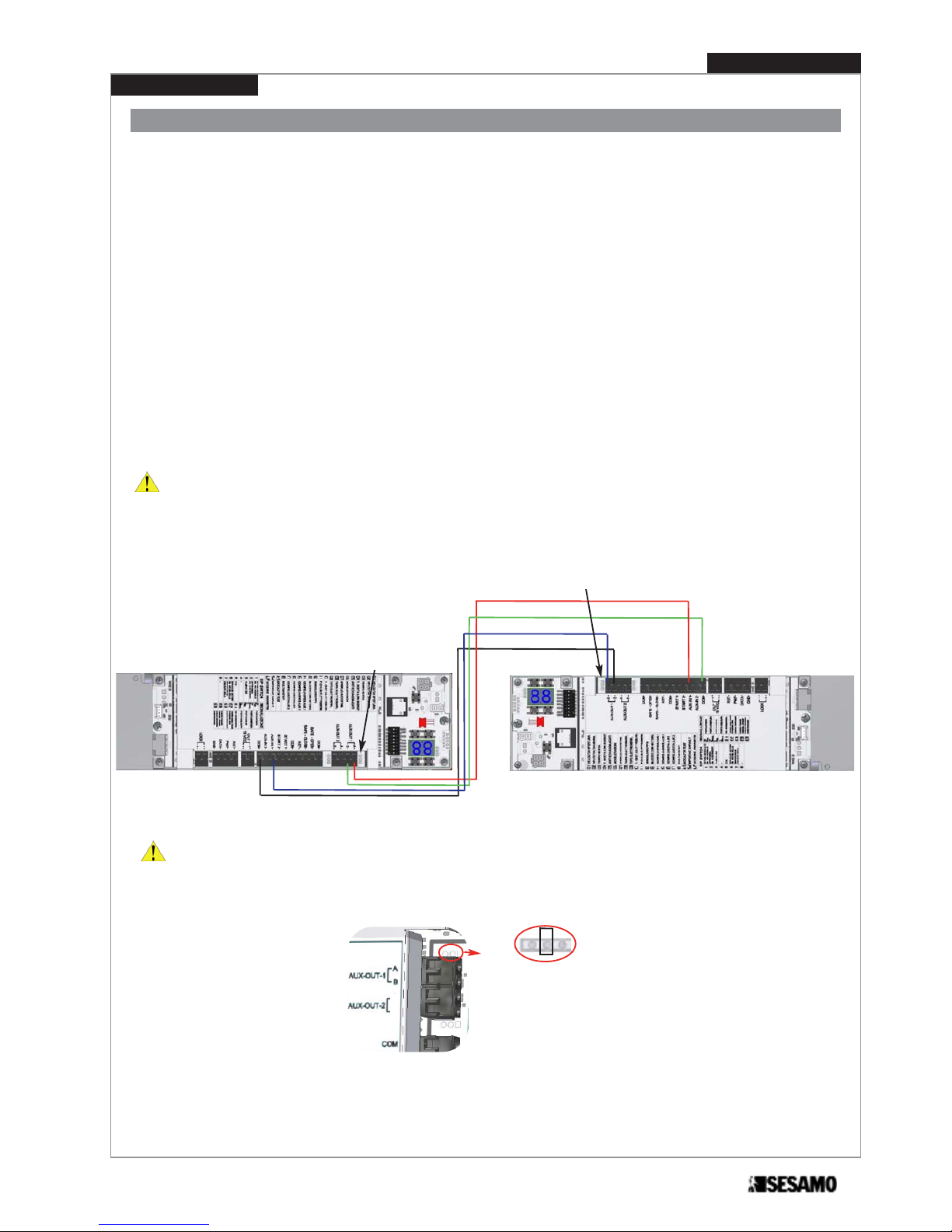
Proswing control board can work in inter lock with another pro swing board. Inter lock means that it is possible to open/close
only one door at a time. To connect two boards proceed as follow (Fig. 37):
• connect “board with priority” AUX IN 1 to “board without priority” AUX OUT 1-A
• connect “board with priority” COM to “board without priority” AUX OUT 1-B
• connect “board with priority” AUX OUT 1-A to “board without priority” AUX IN 1
• connect “board with priority” AUX OUT 1-B to “board without priority” COM
Use 4x0,22 shielded cable, do not connect shield.
Set priority for opening in case of simultaneous command through parameters 15 and 17:
• set parameter
15
=2 on “board with priority”;
• set parameter
17
=1on “board with priority”;
• set parameter
15
=3 on “board without priority”;
• set parameter
17
=1 on “board without priority”;
In this way in case of simultaneous command will open Master as a first door.
Inter lock wiring and use
ATTENTION: In case of inter lock wiring between two double Proswing the wiring has to be made between the
two master boards, whereas one of the two will be considered with priority and the other with out priority to the
interlock functioning.
NPN
PNP
Disconnect jumper near AUX OUT-1 both on board with priority and board without priority (Fig. 38).
Fig. 38
B
A

Power kit (OPTIONAL)
A
B
C
D
Fig. 39
Fig. 40
E
E
PROSWING(M)
Operating instruction
40
Black cable
Red cable
To install power kit batteries proceed as follows:
1- Fix the sponge (A) as shown in Fig. 39, using as reference the aluminum base profile bottom line;
2- Insert the two batteries (C) in the supporting metallic bracket (B) and fix the whole assembling through screw M6x10
(D);
3- Connect cables as shown in Fig. 40;

G
F
Fig. 41
Fig. 42
H
I
Fig. 43
4- Pass cables through springs (E) , then under the control board until the part of control board where is located the
transformer Fig. 41. Fix cables as shown in Fig . 41 (F) and (G).
5- Connect the batteries cables terminal board to control board Fig. 42 (H)
6- Insert control board for batteries (I) on main control board Fig 43
7- Set dip switch 7 =ON and dip switch 6 (=OFF if it is required continuous use after power failure or =ON if it is requi-
red stop open after power failure)- Fig. 44.
Fig. 44
41
PROSWING(M)
Operating instruction
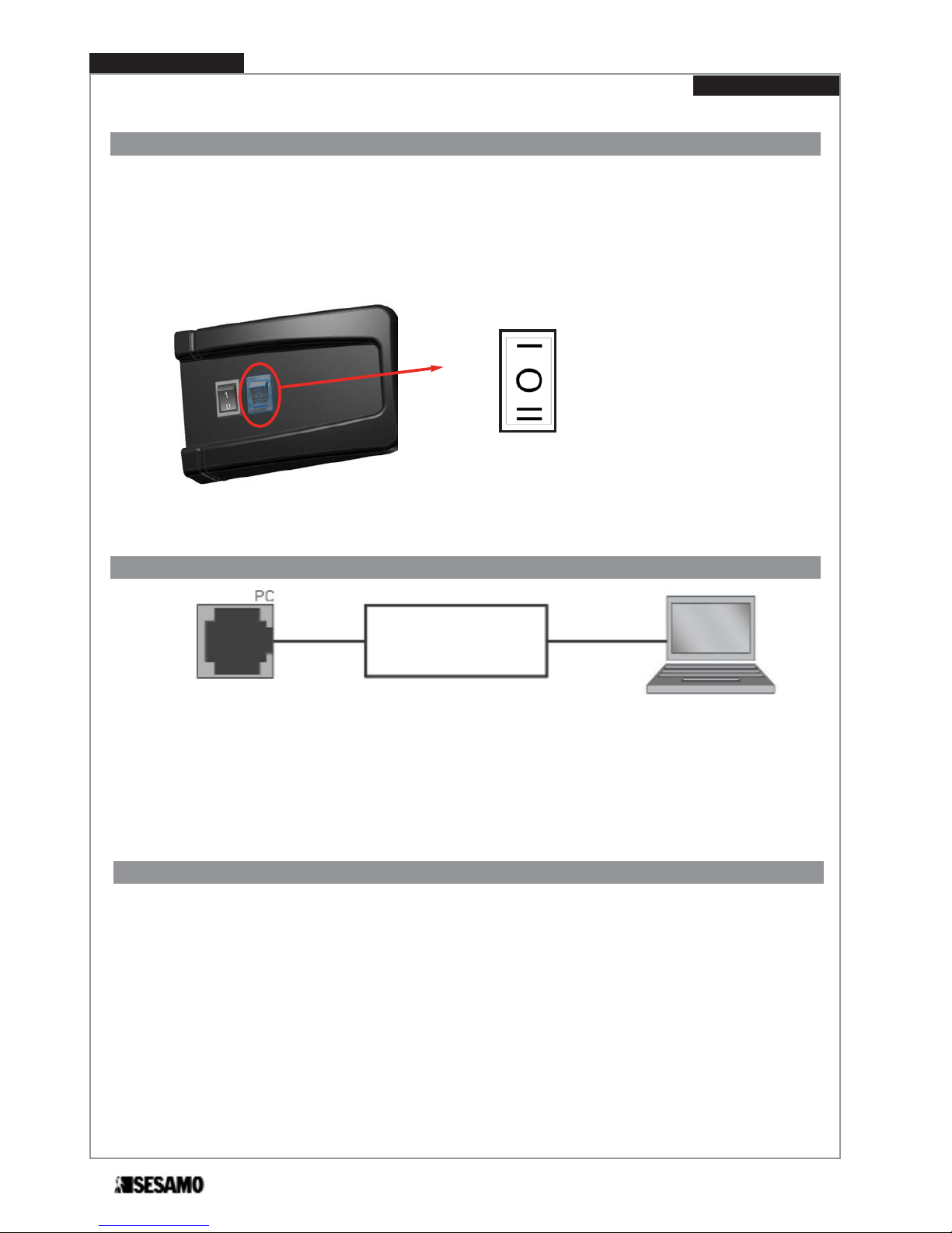
Logic switch
STOP CLOSE
AUTOMATIC
STOP OPEN
Fig. 45
In addiction to base or advanced selectors it is possible to connect a switch selector.
This switch selector has its place near ON-OFF switch, and it is directly wired to control board o it allows three logics:
- STOP CLOSE
- AUTOMATIC
- STOP OPEN
If base or advanced selector is connected, switch selector is excluded.
For PC connection board (optional) is required to connect the PROSWING unit to a Personal Computer. The following is possible with MILLENNIUM WARE software:
• Advanced adjustments of some operating parameter
• Diagnostic and advanced information on status
• Microprocessor programming
PC connection board
Connector for PC - unit connections
Close the automatism’s cover and tight screws.
Hand the guarantee and test certificate over filled according to the instructions shown in the certificate.
The certificates must be sent to SESAMO in 8 days from the positive test date. Hand the technical documentations over to
the client .
Delivery modality
PROSWING(M)
Operating instruction
42
Fig. 46

SESAMO srl
Str. Gabannone, 8/10 • 15030 Terruggia (AL) • Italy
Tel: +39 0142 403223 • Fax: +39 0142 403256
www.sesamo.eu • E-mail: info@sesamo.eu
PROSWING (m)
MAN_PRO.M_EN_0_02_12
 Loading...