


Automatisms for sliding doors
INSTALLATION INSTRUCTION
2

Installation Instruction
LIGHT MILLENNIUM
3
Index
Technical specifications ...................................................................................... page 5
Automatism installation preparation.................................................................... page 5
Automatism description ...................................................................................... page 5
Automatism girder assembly .............................................................................. page 6
Wing assembly and adjustment.......................................................................... page 10
Final operations .................................................................................................. page 14
Power connections .............................................................................................. page 15
MILLENNIUM electronic board............................................................................ page 15
Electrical connections.......................................................................................... page 16
Left Side Electronic Board Connections ............................................................ page 16
Right Side Electronic Board Connections .......................................................... page 17
Led functions ...................................................................................................... page 20
Dip Switch - Selections........................................................................................ page 20
Semi-automatic mode ........................................................................................ page 20
Battery mode ...................................................................................................... page 20
Jumpers .............................................................................................................. page 21
Start up ................................................................................................................ page 21
Inter lock connection and use ............................................................................ page 22
Error Message Table............................................................................................ page 22
SESAMO reserves the right to change the technical specifications of the products, even without notice.

4
Installation Instruction
Thank you for choosing this product. For best automatism
performance, Sesamo recommends you carefully read and
follow the installation and use instructions found in this manual. Installation of this automatism must only be performed
by the professionally qualified personnel for whom this manual is addressed. Any errors during installation may be
harmful to people or things. Packaging material (wood, plastic, cardboard, etc.) should not be scattered in the environment or left within the reach of children as potential sources
of danger. Every installation phase must be performed in
accordance with the regulations in force and following Good
Technique standards. Before beginning installation make
sure that the product is integral and has not been damaged
during transportation or by poor storage conditions. Before
installing the product make sure that each architectural and
structural element of the entrance (girder fastening surfaces,
casings, guide, etc.) is appropriate and sufficiently robust to
be automated. Conduct a careful risk analysis and make
suitable modifications to eliminate conveyance, crushing,
cutting and hazardous areas in general. Do not install the
product in environments where gas, steam or inflammable
fumes are present. The manufacturer is not liable for any
neglect of “good technique” or specific regulations in the
construction of the casing to be motorised and any collapse
of the same. All automatic entrance safety and protection
devices (photocells, active sensors, etc.) must be installed
in accordance with the regulations and directives in force,
with the completed risk analysis, system type, use, traffic,
forces and inertia in play. Pay careful attention to area where
the following may occur: crushing, cutting, conveyance and
any other type of hazard in general applying, if necessary
suitable indications. Indicate the motorised door identification information on every installation. Make sure that the
upstream electrical system is correctly dimensioned and
has all the opportune protections (circuit breakers and
fuses). Only use original spare parts in maintenance and
repairs. Do not tamper or alter devices in the automatism
and all the safety devices in the control panel for any reason.
The manufacturer is not liable if parts within the automatism
are altered or tampered with or if safety devices other than
those indicated by the manufacturer are used in the system.
The automatism installer must provide the automatic
entrance manager with the use manual and all the information required for correct use in automatic and manual
modes (even for electronic locking) and in the event of
emergency.
Pay careful attention to the messages in this manual that are
marked with the hazard symbol. They can either be warnings aimed at avoided potential equipment damage or specific signals of potential hazard to the installer and others.
This device was designed to automate sliding doors. Any
other use is considered contrary to the use foreseen by the
manufacturer who therefore shall not be held liable.
Machine directive
The installer who motorised a door becomes the automatic
door machine manufacturer according to directive 98/37/CE
and must:
• Arrange the Technical Booklet with the documents indicated in attachment V of the Machine Directive and keep
them for at least 10 years.
• Draft the CE declaration of conformity according to
attachment II-A of the machine directive and provide the
use with a copy.
• Apply the CE markings on the motorised door according
to point 1.7.3 of attachment I of the machine directive.
For more information and for assist installers in applying the
specifications of the directives and of European standards
concerning the safe use of motorised gates/doors consult
the guidelines available on internet at the address
www
.sesamo.eu
Machine conformity directive
(Directive 98/37 CE, Attachment II, part B)
Manufacturer: SESAMO S.r.l.
Address: Str. Gabannone 8/10 - 15030
Terruggia - AL
Declares that the product LIGHT MILLENNIUM
• Is built to be incorporated in a machine or to be assembled with other machinery to build a machine considered
by Directive 98/37 CE, as modified;
• Therefore it is not fully compliant to the dispositions of
this Directive since it is not yet assembled with other
components.
• It is in conformity to the following other CE directives:
89/336/CEE Electro-magnetic compatibility and further
modifications 73/23/CEE Low Voltage and further modifications and also declares that the machinery cannot be
used until the machine it is incorporated in or is a component of has been identified and its conformity to
Directive 98/37 CE conditions and national legislation
declared.
Terruggia, 20/06/2003
Aldo Amerio
(Administrator)
LIGHT MILLENNIUM
Installation Instruction
5
Technical specifications
Power supply 230V ac 50 Hz
Nominal power 180 W
External device power 12Vdc – 6W
Emergency battery 24 V 1.2 Ah for about 100 manoeuvres in the event of power failure
Opening speed Adjustable up to 70 cm/sec. (1 wing) or up to 140 cm/sec. (2 wings)
Closing speed 70% of opening speed
Capacity One wing 120 Kg
Two wings 80+80 Kg
Wing dimensions One wing 700÷3000 mm.
Two wings 450÷1500 mm.
Working temperature Internal cross-piece from 0°C to +50°C
Anti-crushing Automatic traction restriction in the presence of obstacles
Weight 8,5 kg per linear meter
Service Intensive
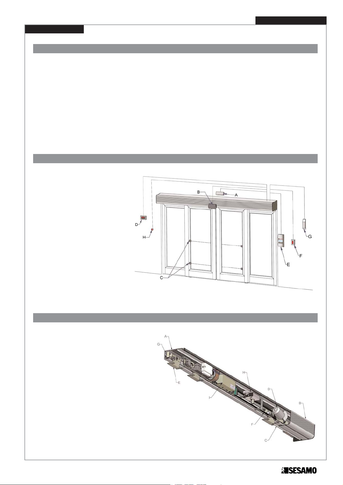
Automatism installation preparation
The automatism is prepared to work
in different accessory and peripheral
configurations. Fig. 1 shows a complete installation where the possible
automatism box access points for
peripheral connections are indicated.
These peripherals include:
A. Entry Radar
B. Exit Radar
C. Safety photocells
D. Circuit breaker (230Vac)
E. Logic selection selector
F. Reset button
G. Manual release handle
H. Safety closing device
Automatism description
The Light Millennium automatism (Fig.2)
is essentially made up of:
A. Extruded aluminium alloy box
B. Extruded aluminium alloy automatism cover
(optional)
C. Bumper profile (optional)
D. Gear motor unit
E. Carriage complete with non-derailment device
and steel wheel.
F. Transmission belt
G. Wing limit stop
H. Electronic wing lock (optional)
I. Integrated movement control modul
Fig. 1
LIGHT MILLENNIUM
Fig. 2
6
Installation Instruction
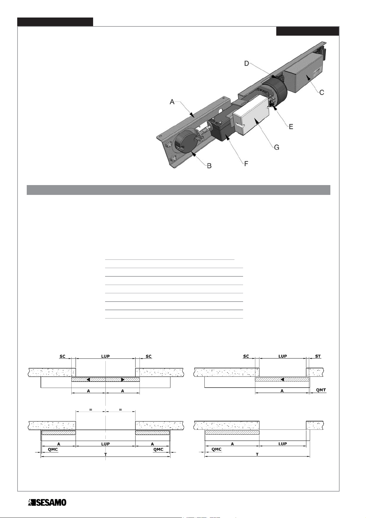
The integrated movement control module (Fig. 3)
is essentially made up of:
A. Base support plate
B. Encoder unit with belt adjustment device
C. Electronic control panel
D. Transformer
E. Mains connection terminal board (230Vac)
F. Emergency battery (optional)
G. Safety electronic key decoder (optional)
Automatism girder assembly
Positioning quotas
The automatism must be centred to the transit area in two-wing cross-pieces so that the wings meet in the middle of the
light space (Fig. 4).
For single wings observe the indications and machine quotas found in Fig. 5.
Cross-pieces with extensions (any unused box areas) should be positioned with the extensions summing QMC and QMT.
For the abbreviations found in Fig.4 and Fig.5 refer to the following table:
Lup: Working transit width
A: Sliding wing width
St: Top wing clearance
Sc : Bottom wing clearance
T : Total box length
QMT : Top machine quota (5mm)
QMC : Bottom machine quota (5mm)
Fig. 4 Fig. 5
Fig. 3
LIGHT MILLENNIUM

Vertical cross-piece positioning must occur so that the
indications in the formulas in:
Fig.6 if standard wing profiles are used;
Fig.7 if Sesamo mod. SMALL wing profiles are used;
Fig.8 if Sesamo mod. MAGNUM wing profiles are used.
For the abbreviations found in Fig.6, Fig.7 and Fig.8 refer
to the following table::
Installation Instruction
7
LIGHT MILLENNIUM
HAF : Fixed wing height
HAS : Sliding wing height
HCa : Automation box height
HCo : Automation cover height
Fig. 6 - Standard wing profiles
Standard
wing profiles
(Fig.6)
Sesamo
SMALL
wing profiles
(Fig.7)
Sesamo
MAGNUM
wing profiles
(Fig.8)
HAS = HAF + 17 mm HAF + 22 mm HAF + 6 mm
HCa = HAF + 47 mm HAF + 54 mm HAF + 44 mm
HCo = HAF HAF + 7 mm HAF - 3 mm
Fig. 7 - Sesamo SMALL wing profiles Fig. 8 - Sesamo MAGNUM wing profiles
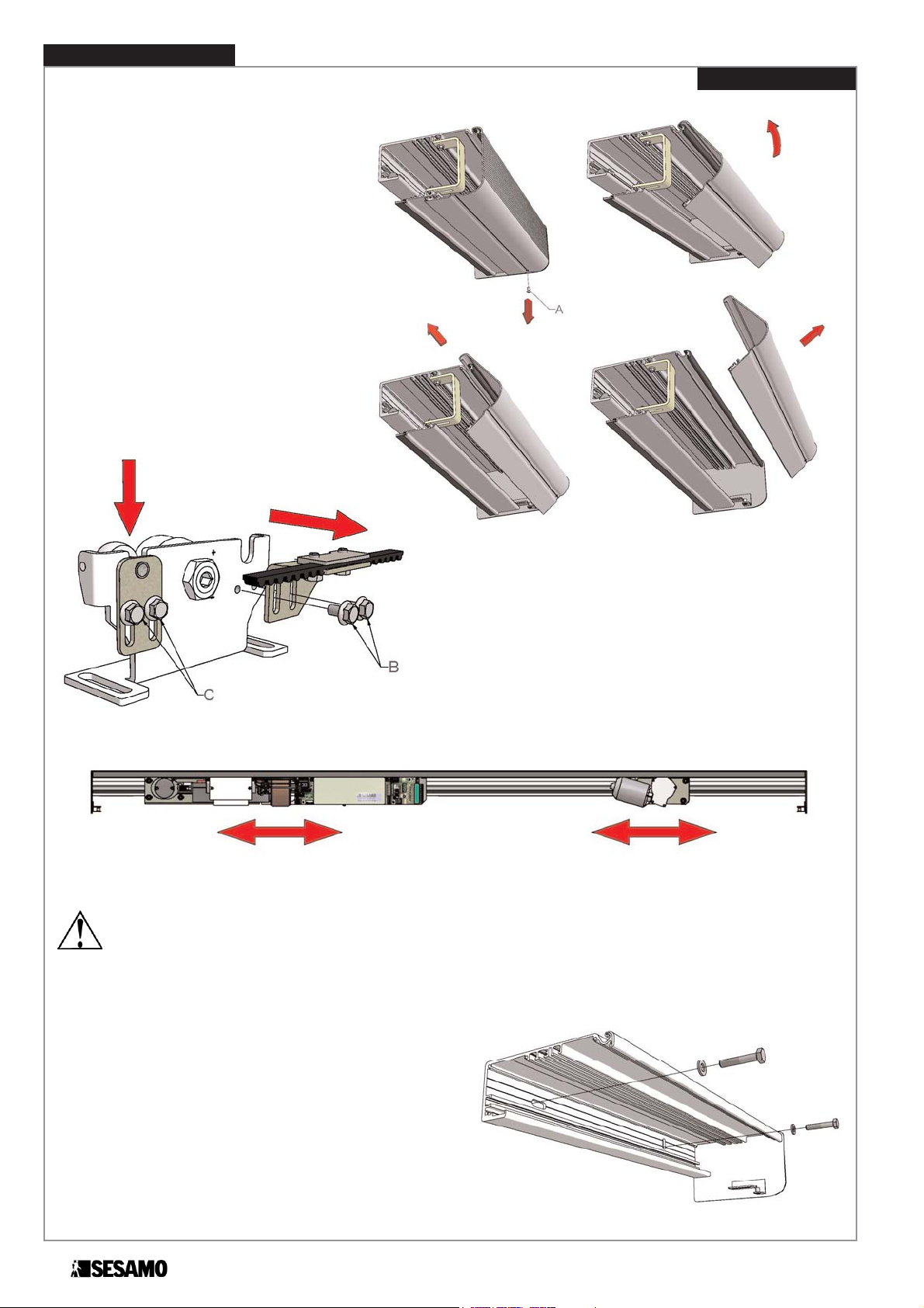
Automatism component removal
and movement
Unscrew the cover fastening screws A (if present) and remove as indicated in the sequence
in Fig.9.
Remove the carriages as follows:
• Disconnect the belt fastening rod from the
carriage using the fastening screws B
(Fig.10)
• Loosen the anti-derailment device screws C
and let the roller support rod completely
lower (Fig.10)
• Remove the carriage
To facilitate box fastening operations, the internal automatism components can be moved or removed.
WARNING
Before loosening component lock screws to move components (Fig.11), measure the distance of the motor from the
head or make marks on the box for correct component positioning at the end of assembly.
Box fastening
Inspect the surface where the box will be fastened, if the surface is not even, level with shims. The automatism girder may
buckle if fastened on an uneven surface.
Fasten the box to the prepared support using suitably long M8
hexagon head cap screws, inserted in the horizontal and vertical slots (Fig.12).
8
Installation Instruction
LIGHT MILLENNIUM
Fig. 9
Fig. 10
Fig. 11
Fig. 12

Installation Instruction
9
According to the type of support, all or only some of the slots on the box are used (Fig.13).
To prevent vibrations or noise during use, make sure that there is a solid fixture every 600 mm and that the box is fastened with the slots closest to the two heads.
WARNING
Before completely tightening the screws, make sure that the girder is “level” in both the length and depth directions
(Fig.14). Positioning errors over the angles indicated in the figure compromise automatism operations.
Fig. 14
LIGHT MILLENNIUM
Fig. 13

Wing assembly and adjustment
Carriage assembly
Fasten the carriages to the wings according to the quotas found in the following diagram (Fig.15).
The quotas indicated in Fig.15 A and B are applied to wings
seen from the inspection side (cover) of automatism.
The Fig.15 B is valid only for automatism with only 1 wing shorter
than 780 mm, with right or left opening and with electric lock. For
all remaining cases (two wings or 1 wings wiith right or left openining) is refer to Fig.15 A.
NOTE: for wings with antipanic break away system or only glass
wing you have to follow the assembling quotas you may find in
manual’s instructions of those accessories.
Use M8 hexagon head cap screws with flat and notched washers
(Fig.16 part.A).
Wing assembly
Make sure that the anti-derailment device is completely lowered by unscrewing the M6 nut (Fig.17, C) and pushing the
indicated wheel downwards (Fig.17 Part.C).
Lift the wing and position the carriages on the sliding rail
paying attention not to damage the rail.
Wing adjustment
Wing adjustment can be made distinctly on three axes based
on installation requirements (Fig.18).
Cross adjustment (Po axis)
Adjust wing position Fig.16 arrow D loosening bolts M8 (Fig.16 part. A) and aligning them to the automatism support surface.
Before tightening bolts A, carefully check that the carriage wheel vertical surface (that coincides with the carriage vertical
surface) is parallel to the box (Fig.18).
10
Installation Instruction
LIGHT MILLENNIUM
Fig. 17
Fig. 16
Fig. 15

If uneven proceed as follows:
• Loosen bolts (Fig.16 part.A)
• Align the carriages to the automatism box
• Check alignment measuring the quotas E (Fig.18) on the right
and left sides of the carriage: they must be equal.
• To further test alignment, manually move the wing: it should slide
with the minimum effort and without any type of hindrance or
friction.
• Tighten the bolts (Fig.16 part.A) paying careful attention not to
alter the alignment.
WARNING
Neglect to align the carriage wheels with the sliding rail may cause
excessive wear and noise during automatism use
Vertical adjustment (Pv axis)
To position the wings at the correct height and as perpendicular
as possible, proceed as follows:
• To avoid damages, make sure the anti-derailment device is
completely lowered.
• Insert a (long-handled) Allen wrench in the wheel eccentric
part. A Fig. 19,loosen the nut using a long-handled 24
wrench part B.
• Use the eccentric to move the wing to the required height
using the references (+and-) on the carriage and on the
eccentric part C.
• Holding the eccentric securely in position, firmly tighten the
wheel nut making sure not to alter the chosen position.
Horizontal adjustment (Pt axis)
Its purpose is to adjust the meeting point of the two wings.
Sesamo automatisms are designed positioning components
to obtain the correct meeting of the wings at the centre of the
space. If the meeting point requires adjustment during installation, proceed as follows:
• Loosen bolts (Fig.20) regarding the clamp on the “pass-
ing branch” of the belt (joint-less belt branch)
• Move the clamp on the belt to the required position.
• Firmly tighten the bolt (Fig.20 part.A) carefully checking
that the belt teeth are correctly inserted in the clamp housings.
Installation Instruction
11
LIGHT MILLENNIUM
Fig. 18
Fig. 19
Fig. 20

12
Installation Instruction
Belt tensioning
Proceed as follows for correct belt tensioning:
• Make sure the motor unit is positioned and fixed as per factory settings and is a position that guarantees belt centring
to the sliding area
• Loosen the fastening nuts on the encoder pulley unit A (Fig.21)
• Completely move the tensioning nut back B
• Make sure that integrated automatism control module fastening bolt part. C is
loose and permits lateral movement.
• Move the integrated automatism
control module to the left to achieve
first belt tensioning level. Make sure
that the belt branches are visibly taut
(without any evident downward
folds).
• Firmly tighten module fastening
screws C on the automatism girder.
• Rotate the tensioning nut B pushing
down the spring D to the limit E
• Tighten the encoder pulley unit fastening nuts A
Carriage start up
Reconnect the belt fasteners to the carriages Fig.10; tighten the
screws B making sure the position of the fasteners permits
good belt parallelism between the upper and lower branches.
Verify the correct disposition of the belt fasteners on the
carriages in touch with the automatism as indicated in
Fig. 23, 24 and 25.
Lift the anti-derailment device so that the roller does not touch the
aluminium profile during sliding (Fig.22). Tighten the
screws C (Fig.10) without altering the chosen adjustment.
In touch with the automatism, verify the correct fixing
configuration of the belt clamp on the carriages, as indicate
in the figures:
• Fig. 23 part C, D for two wings automatism
• Fig. 24 part. C with 1 wing automatism and left opening
• Fig. 25 part. D with 1 wing automatism and right opening
WARNING
Incorrect anti-derailment device adjustment that puts the roller in contact with the aluminium profile causes excessive noise
during automatism use.
WARNING
An incorrect fixing of the belt clamp on the carriages causes alterations in the direction of the opening and closing wings. Verify
carefully the agreement of the connections between the belt and the carriages as indicated in the Fig.25, 26 and 27.
LIGHT MILLENNIUM
Fig. 21
Fig. 22

Wing limit stop adjustment
2 wing Automatism: on of the two limits is found on the left end of the girder (Fig. 23 part. A) and the other near the
centre of the right wing (Fig. 23 part.B).
1 wing Automatism: the two limits are found on the ends of the left (Fig. 23, 24 part. A) and right (Fig. 23,24 part. B)
sliding area and near the girder heads.
To adjust the limit stops loosen screws as indicated in Fig. 22, 23, 24 part. A,B then slide the limit to the required position and then tighten the screws.
If necessary, fine adjustments of the wing stop point can be made using the carriage rubber screw stop Fig. 22, 23, 24
part. G
Installation Instruction
13
LIGHT MILLENNIUM
WARNING
Before putting the automatism into operation, always make sure that the fastening
screws of the stop brackets have been correctly tightened.
Fig. 23
Fig. 24
Fig. 25
2 Wings
1 Wings
Left Opening
1 Wings
Right Opening

Electronic lock adjustment
• Make sure the limit block runner is evenly positioned on the
carriage observing the automatism configuration
(Fig.23, 24, 25 part. F).
• Move the wing(s) to the totally closed position.
• Slide the electronic lock until the bar is near the limit block
(Fig.26) (distance ~2 mm.) and tighten the screws.
• Drill a hole (ø 9mm) in the automatism cover near the release
rod for future key insertion (Fig. 26).
Manual release
The purpose of the supplied key is to manually activate the
electronic lock in the event of power fault or failure.
If its use is required, proceed as follows :
• Insert the provided key in the hole on the part under the
automatism cover.
• Turn the key clockwise until mechanical stop and keep
it in this position.
• Move the wing ten centimetres towards the opening and
remove the key: the wings are now released.
To lock the wings again, move them to the completely closed position.
Final operations
Before starting the automatism, check and perform the following:
• Accurately remove and dust or shavings from the rails and carriage wheels
• Check correct tightening of the carriage wheel screws and nuts.
• Check correct belt tensioning.
• Check that the wires are fixed and that no wire pass near the carriage sliding area.
• Check that the limit stops are correctly positioned and that the belt clamps do not touch the toothed pulleys.
• Spread a thin layer of common bearing grease on the rails and transmission belt.
• Verify the plastic joint in the gear motor system is properly lubricated with normal grease for bearings.
WARNING
The rails and transmission belt can work without lubrication without presenting wear. However, light lubrication prevents
noise when parts are not perfectly aligned.
14
Installation Instruction
LIGHT MILLENNIUM
Fig. 26
(Hole ø=9mm)
(Hole ø=9mm)

Power connections
WARNING
Before performing the following operations make sure the mains are disconnected. Before powering the equipment,
perform the controls foreseen in paragraph “Start up”.
Place the power cord in the automatism paying careful attention not to damage the cord against any metallic edges.
Connect mains and grounding wires on the terminal board (Fig. 27)
WARNING
Never invert the power wire with the grounding
wire. Do not replace the mains fuse with a fuse
other than the one foreseen by the manufacturer: T 1 A (delayed).
Power must be isolatable from the general
panel with a bi-polar switch with minimum contact opening equal to 3 mm. (not supplied).
MILLENNIUM electronic board
The meanings of the main electronic board components are listed in Fig. 28:
Installation Instruction
15
Transformer
fuse
(F 6,3A)
Power
switch
Transformer
connector
Battery
connector
Electronic
lock fuse
(T 1A)
Electronic
lock connector
Motor
connector
Battery fuse
(F 6,3A)
Battery
charge board
connector
(optional)
Photocell
board connector
(optional)
Photocell ray
connector
(only used with optional
photocell board)
External peripher-
al power fuse
(T 500mA)
External peripheral
power connector
External
peripheral
connector
Factory only
use connector
Dip Switchs
and selection
Jumpers
START opening
control button
PC
connector
Multi-logic
selector
connector
Fig. 28
Encoder
connector
LIGHT MILLENNIUM
Fig. 27
Jumper
INT/EXT

Electrical connections
WARNING
All board or peripheral connections on the terminal board
must be performed with the power disconnected to
prevent irreparable damage to the electronic equipment.
WARNING
Any repairs or replacements must be performed by
professionally qualified personnel and original spare
parts must be used in repairs.
Left Side Electronic Board
Connections
Fig. 30 summarises terminal connections on the left side of the electronic board:
16
Installation Instruction
Fig. 29
Connectors must be inserted
as in Fig. 29
LIGHT MILLENNIUM
The battery charge unit (optional) is inserted
in the terminal board (part. A) observing the
assembly direction as shown in Fig. 29
Verify the agreement
between the power
motor cable and the
serigraphy indicated in
the electronic board
Electric Transformer
Battery
Encoder
Electric Lock
Gear Motor
Fig. 30
Part. A
Blue Red

Installation Instruction
17
Right Side Electronic Board Connections
A. Photocell amplifier board connector (optional)
Insert the amplifier module observing the assembly direction shown in Fig. 29
WARNING
Select the Jumper for single or double beam and check the red led
B. Photocell beam connector
(only use if the internal photocell amplifier board module is installed)
C. Selector Jumper between Millenium - and external cell amplifier
The system has three selectable working models:
A Millenium amplifier only Jumper close towards INT
B External amplifier only Jumper close towards EXT
C Both Millenium + External amplifier Jumper open
Fig. 31
BEAM OFF
On
) Beam interrupted
Off
) Correct
JUMPER
Closed towards B2
) Double beam
Closed towards B1
) Single beam
Fig. 32
Fig. 33
A RED
small band
distinguishes
the Transmitter
A WHITE
small band
distinguishes
the Receiver
Connect the
photocell’s beams as
in Fig. 33
LIGHT MILLENNIUM
INT EXT
A B D E
F
G
C

D. Multi-logic selector connector
Use the four conductors in the shielded wire for connections, observing the correspondences indicated by the markings
on the terminal board and multi-logic selector.
Do not connect the shield of the wire used.
For further information on multi-logic selector use, see the instructions for use.
E. External peripheral power connector – 12 Vdc 6W max (500mA)
Real power value may vary from 12 Vdc to about 15 Vdc depending on the resistive load situations connected
to these terminals.
WARNING
Do not invert power polarity. When the green led D39 is on it indicates normal voltage presence 12V. If off check:
• For mains and/or battery voltage
• That fuse F1 is not interrupted
F. External peripheral connector
ADVANCED
SELECTOR
BASE
SELECTOR
Shielded cable with 4 wires 0,22 mm.
(Do not connect the shield of the wire
used)
Fig. 34
Fig. 35
Fig. 36
18
Installation Instruction
LIGHT MILLENNIUM

* NA = Normally open NC = Normally closed
The electrical signal from external peripherals can be varied through the advanced selector or PC connection: from normally closed to normally open and vice versa. See the advanced selector used manual for further details.
G. Connector for PC - unit connections
A PC connection board (optional) is required to connect the MILLENNIUM unit to a Personal Computer.
The following is possible with MILLENNIUMWARE software:
• Advanced adjustments of some operating parameters
• Diagnostics and advanced information on unit status
• Microprocessor programming
PC connection board
Fig. 37
Installation Instruction
19
LIGHT MILLENNIUM
SIGNAL
COM
SAFE CLOSE
AUX IN
AUX OUT
SAFE OPEN
KEY
START 1
START2
TYPE*
NC
NA
NA
NC
NA
NA
DESCRIPTION
Common electrical signal.
Signal for the connection of an external
photocell or safety control device for
wing closing
.
Auxiliary input signal. Auxiliary devices
can be connected to this signal. It is
normally used for inter lock functions.
Auxiliary output signal, PNP transistor
type for particular door condition signals (reset, open, closed, etc).
Signal for the connection of sensors for protection during wing opening.
Lock signal. Closure devices can be
connected such as electronic key, key
selector, transponder, etc.
The signal can be controlled in bi or
mono-stabile mode with an activation
time equal to about 500 msec. For
mode type selection see paragraph
JUMPERS.
Opening signal. Wing opening devices
can be connected.
Opening signal. Wing opening devices
can be connected.
FUNCTION
If the door is closing and the contact opens, the unit sends and
immediate motion inversion command. Closing will only recommence after the contact closes.
The signal must be short circuited with COM if not devices
(internal or external) are connected.
When used as an auxiliary signal the function logic can be
personalised according to customer requests.
When used as inter lock logic, closing this signal inhibits door
functions that will not open even with open signal presence.
According to the type chosen signal, the output becomes
active (12Vdc and led on) when the door is in the set condition (Reset, open, closed, etc). See the advanced selector
manual for further details.
If the door is opening and the contact closes, the unit sends an
immediate movement stop command. Opening will only continue after this signal is deactivated.
If the signal opens the unit sends a complete wing closure
command (from any position) From this moment until the signal is closed the door stays in this position and no external
peripheral is detected (including multi-logic selectors). As
soon as the signal closes the door opens permitting access.
The signal must be short circuited with COM if no devices
are connected.
Closing this signals causes the wings to open. This signal is
only monitored in 2 Radar logic.
Closing this signals causes the wings to open. This signal is
monitored in both 2 Radar and 1 Radar logic.

LED Functions
Dip Switch - Selections
WARNING
For correct automatism functions and to guarantee the optimisation of the parameters that regulate wing movement,
adjust wing weight using dip switches S1 and S2 as indicated below.
Semi-automatic mode
Battery mode
Semi-automatic mode enabled.
In this mode wings close similar to
how they open, it doesn’t start
automatically but must be controlled by the operator.
Semi-automatic mode disabled
(Default). In this mode the closing’s
wings starts automatically after a
time according to the idle time’s
setting.
In the event of power failure the
equipment continues working
powered by the battery. (Default).
In the event of power failure, the
equipment moves the doors to
the “Stop open” position, and
stays in this condition until power
returns or a new logic is selected
using the multi-logic selector.
20
Installation Instruction
LIGHT MILLENNIUM
N° Wings
Weight per
wing (kg)
2 30 ÷ 60
1 60 ÷ 120
N° Wings
Weight per
wing (kg)
2 0 ÷ 30
1 0 ÷ 60
N° Wings
Weight per
wing (kg)
2 60 ÷ 80
ON indicates mains
voltage present
ON
indicates
encoder
signal
presence
ON indicates electronic
lock power
ON indicates motor
power supply
ON indicates 12V external
peripheral power supply
Diagnostics Led
(see Error Message Table)
External peripheral
signal presence led.
Fig. 38
Factory use only

Jumpers
Jumpers ON OFF (Default)
J1 Power on Power off
J2 Not used Not used
J3 Cyclic opening No cyclic opening
J4 Mono-stable Bi-stable
Start up
WARNING
If no optional operation lock device is installed, make sure the KEY input is short circuited with the COM input. Otherwise
the equipment cannot be started.
If no safe close device (internal and external) is installed, make sure the SAFE CLOSE input is short circuited with the
COM input and the jumper INT/EXT (Part. C pag. 17) in EXT. Otherwise the equipment cannot be started.
WARNING
For correct automatism functions and to guarantee the optimisation of the parameters that regulate wing movement,
adjust wing weight using dip switches S1 and S2 as previously indicated.
Position wings ~20 cm from total closure. Turn the power switch to 1 to power the equipment.
The automatism resets limits to reduced speed first completely opening and then closing.
WARNING
If necessary, make a dynamometric control to verify any slide friction, turn off the equipment and remove the gear motor
unscrewing the specific rubber supports.
Eliminate friction causes and start the equipment again repeating the above-described movement.
Multi-logic selector not installed: when the equipment finishes limit reset it is ready to work in 2 RADAR logic.
Multi-logic selector installed: when the equipment finishes limit reset it is ready to work and is positioned in the
“STOP CLOSED” logic.
At the end of reset the equipment is ready for use; check correct sensor operations for opening command and safety control. Also check anti-crushing sensitivity; if the value requires increasing and decreasing, see the advanced selector manual.
To test automatism operations without connections to the open command device use the START button on the unit (see
Fig. 28)
J1: activates motor power supply in completely closed position to generate continual
drive even in the wings stopped and closed position.
J2: not used
J3: cyclic opening generator to test door operations;
J4: KEY signal operating type selection (see external peripheral connector
description): mono-stable (Activation time 500 ms) or bi-stable
Installation Instruction
21
LIGHT MILLENNIUM

DESCRIPTION
Initialization error
Door blocked error
Anti-crushing in
opening error
Anti-crushing in
closing error
Inversion error
Overcurrent error
Encoder error
NUM.
1
2
3
4
5
6
7
WHAT TO DO
An error occurred during initialisation, in particular, the measured
opening quota is too low. Check the encoder, the connection
between the encoder and mother boards. Make sure the transit
area is free of obstacles. In the event of electronic lock, check
correct operations.
The door cannot open. Make sure there are no obstacles in the
transit area and that there are no locks (electric or manual) that
block the door.
After three opening and anti-crushing detection attempts.
Make sure there are no obstacles in the transit area.
Make sure that the anti-crushing sensitivity in opening is not too
low. Check the encoder, the connection between the encoder
and mother boards.
After three closing and anti-crushing detection attempts. Make
sure there are no obstacles in the transit area. Make sure that the
anti-crushing sensitivity in opening is not too low. Check the
encoder, the connection between the encoder and mother
boards.
An inversion error of the movement between the encoder and
motor was detected. Make sure that the motor is correctly
connected as shown in Fig. 30
Motor overload detected. Make sure there are no short circuits
on the motor power cord. Check the motor and replace if
necessary.
Encoder malfunction detected.
Check the encoder, the connection between the encoder and
mother boards.
AV
BL.
BL.
BL.
BL.
BL.
BL.
BL.
OC
OFF
OFF
OFF
OFF
OFF
ON
OFF
LED
L1
OFF
OFF
OFF
ON
ON
ON
ON
L2
OFF
ON
ON
OFF
OFF
ON
ON
L3
ON
OFF
ON
OFF
ON
OFF
ON
Inter lock connection and use
The MILLENNIUM unit is set to work in inter lock mode through
connections to an electronic unit of the same family.
In inter lock mode one door can only open if the other is not moving, that is, if not in the movement phase.
To inter lock two automatisms proceed as follows (Fig. 39):
• connect the terminal AUX IN of unit A to the terminal AUX OUT
of unit B
• connect the terminal AUX OUT of unit A to the terminal AUX IN
of unit B
• connect terminal “-“ of the 12Vdc power supply of unit A to the terminal “-“ of the 12Vdc power supply of unit B.
Use 4 x 0.22 shielded wire for connections and do not connect
the shield.
Error Message Table
When open requests come from the both sensors on both doors
an opening priority needs to be set; to do this, set one door as
MASTER and the other as SLAVE.
When simultaneous signals occur, the MASTER door will open.
To select MASTER and SLAVE use the advanced selector.
Fig. 39
UNIT A
UNIT B
22
Installation Instruction
BL. = Blinking
LIGHT MILLENNIUM
Delivery Modality
Close the automatism’s cover following the reverse procedure used to remove it.
Make sure the two fixing screws of the cover are well tightened.
Before to end the automatism’s installation, remember to stick the labels on the sliding wings.
Hand the guarantee and test certificate over filled according to the instructions shown in the certificate.
The certificates must be sent to SESAMO in 8 days from the positive test date. Hand the technical documentations over to
the client.

23

SESAMO srl
Str. Gabannone, 8/10 • 15030 Terruggia (AL) • Italy
Tel: +39 0142 403223 • Fax: +39 0142 403256
www.sesamo.eu • E-mail: info@sesamo.eu
MAN_LM_EN_4_12_07
 Loading...