

1
INSTALLATION & OPERATION MANUAL
GAS RESTAURANT RANGES
Models: SGR-4, SGR-2-12G, SGR-24G,SGR-6,
SGR-2-24G, SGR-4-12G, SGR-10, SGR-6-24G,
SGR-4-36G
2
3
IMPORTANT FOR YOUR SAFETY
THIS MANUAL HAS BEEN PREPARED FOR PERSONNEL QUALIFIED TO
INSTALL GAS EQUIPMENT, WHO SHOULD PERFORM THE INITIAL FIELD
START-UP AND ADJUSTMENTS OF THE EQUIPMENT COVERED BY THIS
MANUAL.
POST IN A PROMINENT LOCATION THE INSTRUCTIONS TO BE FOLLOWED IN
THE EVENT THE SMELL OF GAS IS DETECTED. THIS INFORMATION CAN BE
OBTAINED FROM THE LOCAL GAS SUPPLIER.
4
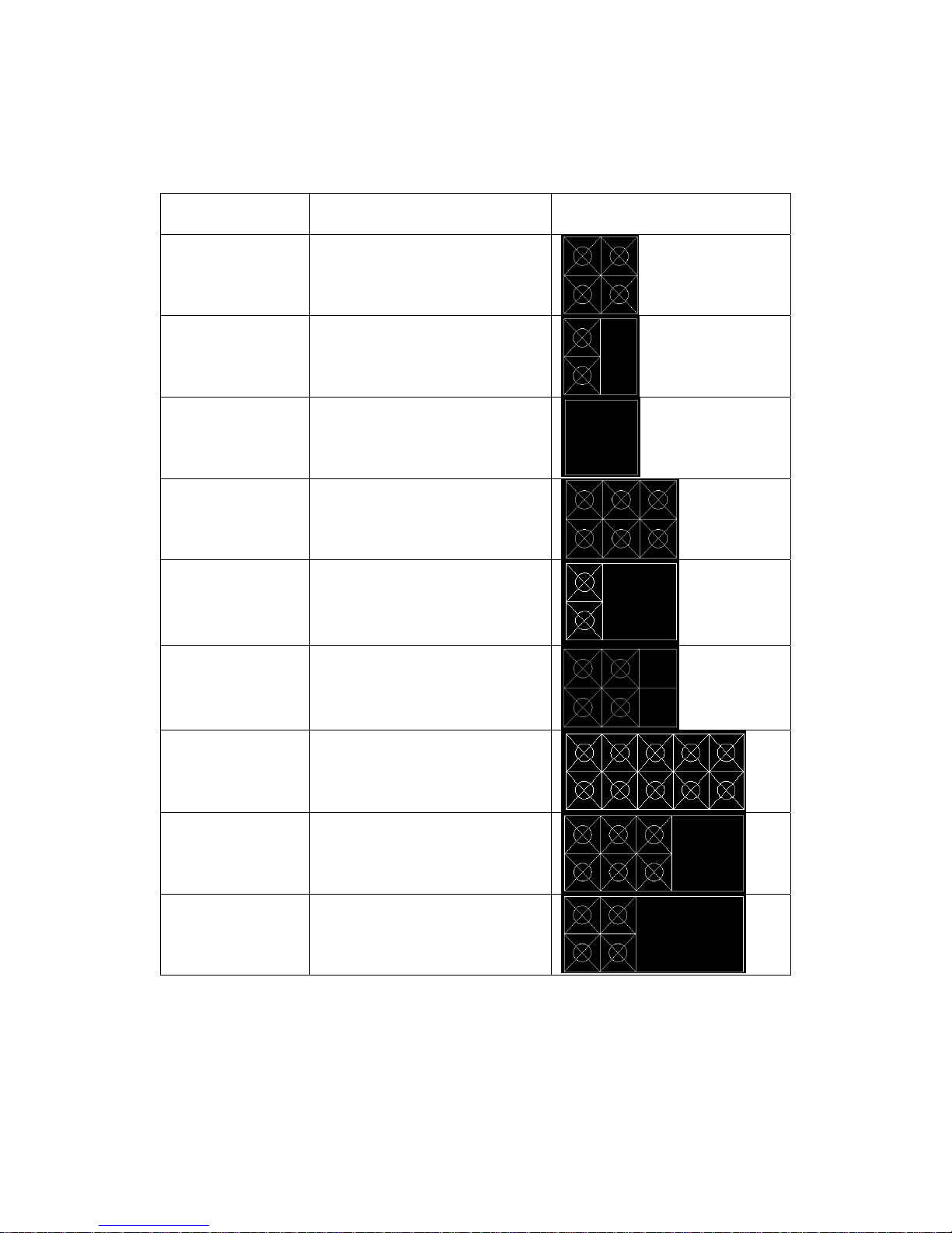
ModelListview
Model No. Description View
SGR-4 4 top burner range,
one 24” oven
SGR-2-12G 2 top burner range,
one 12” top griddle,
one 24” oven
SGR-24G 1 24” top griddle, one
24” oven
SGR-6 6 top burner range,
one 36” oven
SGR-2-24G 2 top burner range,
one 24” top griddle,
one 36” oven
SGR-4-12G 4 top burner range,
one 12” top griddle,
one 36” oven
SGR-10 10 top burner range,
two 36” oven
SGR-6-24G 6 top burner range,
one 24” top griddle,
two 36” oven
SGR-4-36G 4 top burner range,
one 36” top griddle,
two 36” oven
5
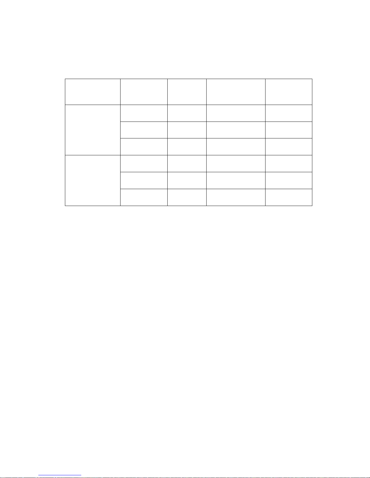
Orifice size & BTU
Descripti
on
Pressure
BTU per
burner
Orifice
size
Toleranc
e(mm)
top burner
range/top
griddle
4"(NAT) 30,000 2.55mm/#39 ±0.02
5"(NAT) 30,000 2.4mm/#41 ±0.02
10"(LP) 27,000 1.55mm/#53 ±0.02
oven
4"(NAT) 33,000 2.9mm/#33 ±0.02
5"(NAT) 33,000 2.6mm/#38 ±0.02
10"(LP) 28,000 1.5mm/#53 ±0.02

6
Installation, Operation and Care:
PLEASE KEEP THIS MANUAL FOR FUTURE REFERENCE
GENERAL
SERV-WARE ranges are produced with quality workmanship and material. Proper
installation, usage and maintenance of your range will result in many years of
satisfactory performance.
SERV-WARE suggests that you thoroughly read this entire manual and carefully
follow all of the instructions provided.
THIS APPLIANCE IS EQUIPPED FOR NATURAL GAS,
for conversion to LP gas please see gas conversion
instruction manual attached. Orifices necessary for LP
(propane) (natural) conversion are provided. Please refer
to page 3 the orifice size list when you do gas conversion
INSTALLATION
UNCRATING
This range was inspected before leaving the factory. The transportation company
assumes full responsibility for safe delivery upon acceptance of the shipment.
Immediately after unpacking, check for possible shipping damage. If the range is
found to be damaged, save the packaging material and contact the carrier within 15
days of delivery.
Uncrate unit carefully and place in a work-accessible area as near to its final
installed position as possible. Remove all shipping wire and wood blocking.
Before installing, check the type of gas supply (natural or propane) to make sure
they agree with the specifications on the rating plate located on the inside of the
lower kick panel. If the supply and equipment requirements do not agree, do not
proceed with the installation. Contact your dealer or SERV-WARE Company
immediately.
LOCATION
The appliance must be installed under a ventilation hood.
The equipment area must be kept free and clear of combustible substances.

7
The range, when installed, must have a minimum clearance from combustible
construction of 12" (304 mm) at the sides and 10" (253 mm) at the rear. Clearance from
non-combustible construction is 0" at the sides and 6" (152 mm) at the rear.
The installation location must allow adequate clearances for servicing and proper
operation. A minimum front clearance of 40" (1016 mm) is required.
The range must be installed so that the flow of combustion and ventilation air will not
be obstructed. Adequate clearance for air openings into the combustion chamber
must be provided. Make sure there is an adequate supply of air in the room to allow
for combustion of the gas at the burners.
INSTALLATION CODES AND STANDARDS
Ranges must be installed in accordance with:
In the United States of America:
1. State and local codes.
2. National Fuel Gas Code, ANSI/Z223.1 (latest edition). Copies may be obtained
from The American Gas Association, Inc., 1515 Wilson Blvd., Arlington, VA22209.
In Canada:
1. Local codes.
2. CSA B149.1 Natural Gas and Propane Installation Code.
3. CSA C22.1 Canadian Electric Code.
4. CSA C22.2 Canadian Electric Code.
The above are available from the Canadian Standard Association, 5060 Spectrum Way, Suite
100, Mississauga, Ontario, Canada L4W 5N6.
ASSEMBLY: Ranges Mounted on Casters
Ranges mounted on casters must use a flexible connector (not supplied by SERV-WARE)
that complies with the Standard for Connectors for Movable Gas Appliances,
ANSI-Z21.69 • CSA 6.16 and a quick-disconnect device that complies with the Standard
for Quick-Disconnect Devices for Use With Gas Fuel, ANSI-Z21.41 • CSA 6.9. In
addition, adequate means must be provided to limit movement of the appliance without
depending on the connector and the quick-disconnect device or its associated piping to

8
limit appliance movement. Attach the restraining device at the rear of the range as shown
in Fig. 1.
Remove two screws from the rear of the range and install the tie-down strap shipped with
the casters using these screws (Fig. 1).
Attach the gas line strain relief to the tie-down
strap at the rear of the range (Fig. 1).
If disconnection of the restraint is necessary, turn off the gas supply before disconnection.
Reconnect this restraint prior to turning the gas supply on and returning the range to its
installation position.
Separate instructions for installing casters to the range are included with the casters.
Note: If the range is installed on casters and is moved for any reason, it is recommended
that the range be leveled front to back and side to side.

9
Backsplash
The standard Restaurant Range is equipped with a 23" (584 mm) high backsplash and
shelf.
1. Remove the backsplash components from the crating materials.
2. Assemble the required components as shown in Fig’s. 8 and 9 and 10.
3. Tighten the four screws to secure the shelf.

10
4 Lift the assembly up, sliding the channels into the space provided at the rear of the
range.(Fig’s. 11).
5. Install four #10 sheet metal screws (2 to each channel leg) (Fig. 12).
Fig. 12

11
LEVELING
Check the leveling of the range. Place a level inside the oven cavity across the
oven rack(s). Level front-to-back and side-to-side.
To adjust the leveling, tilt the range to one side and, using channel locks, unscrew
the adjustable leg insert as required. Repeat this procedure as necessary for each
leg.
Optional casters for this range are of the non-adjustable type. Therefore, the floor
must be level. If floor surface is not level, the range will experience cooking
problems.
GAS CONNECTIONS
CAUTION: All gas supply connections and any pipe joint compound used must be
resistant to the action of propane gases.
Each range is factory-equipped for the type gas specified on the rating plate. The
installation gas connection is a
3
/4" (19 mm) 14 FPT ANSI schedule #40 standard pipe.
Connect gas supply. Make sure the pipes are clean and free of obstructions. Codes
require that a gas shutoff valve be installed in the gas line ahead of the range. Standard
ranges are equipped with fixed burner orifices which coincide with installation elevation.
Install the gas pressure regulator.
Before installing, ensure that regulator supplied agrees with rating plate gas supply.
The gas pressure regulator is NOT factory installed. The regulator for this gas type
is sealed within a plastic bag attached to the oven rack inside the oven cavity. This
regulator must be field installed by a qualified installer.
Natural gas regulators are preset for 5" W.C. (Water Column) (.99 kPa);
propane gas regulators for 10.0" W.C. (2.5 kPa)
1. Locate
3
/4" (19 mm) gas connection pipe extending from rear of range.
2. Cover pipe threads with leak sealant.
3. Screw regulator hand-tight onto pipe with regulator arrow pointing towards range
body back (Fig. 13).
4. Using pipe wrench, tighten regulator securely in an upright position (Fig. 13).

12
Fig. 13
The arrow on the regulator shows the direction of the gas flow. The pressure
regulator must be mounted horizontally to ensure proper preset outlet pressure. If
the regulator is installed in any other position, the outlet pressure must be reset for
proper operation.
A leak limiter is supplied with every regulator to allow excess gas pressure to
escape. Do not obstruct leak limiter on gas pressure regulator, as obstruction may
cause regulator to malfunction.
WARNING: PRIOR TO LIGHTING, CHECK ALL JOINTS IN THE GAS
SUPPLY LINE FOR LEAKS. USE SOAP AND WATER SOLUTION. DO NOT
USE AN OPEN FLAME.
After piping has been checked for leaks, all piping receiving gas should be fully purged to
remove air.
Before operation, verify thermocouple is securely seated in the safety valve. The
thermocouple should be tightened a
1
/4 turn past finger tight. DO NOT OVERTIGHTEN.
Over-tightening may damage the thermocouple or safety magnet.
TESTING THE GAS SUPPLY SYSTEM
When gas supply pressure exceeds
1
/2 psig (3.45 kPa), the range and its individual
shutoff valve must be disconnected from the gas supply piping system.
When gas supply pressure is 1/
2 psig(3.45kPa) or less, the range should be isolated
from the gas supply system by closing its individual manual shutoff valve until the
range is ready for start-up.
FLUE CONNECTIONS DO NOT obstruct the flow of flue gases from the flue located on

13
the rear of the range. It is recommended that the flue gases be ventilated to the outside of
the building through a ventilation system installed by qualified personnel.
From the termination of the flue to the filters of the hood venting system, a minimum
clearance of 18" (457 mm) must be maintained.
Information on the construction and installation of ventilating hoods may be obtained from
the standard for the "Removal of Vapors from Commercial Cooking Equipment”, NFPA
No. 96 (latest edition), available from The National Fire Protection Association,
Batterymarch Park, Quincy, MA 02269.
OPERATION
WARNING: THE RANGE AND ITS PARTS ARE HOT. BE VERY CAREFUL WHEN
OPERATING, CLEANING OR SERVICING THE RANGE.
CONTROLS
THERMOSTAT DIAL
Allows operator to regulate oven temperature from low to 500° F (260° C)
(OPTIONAL) GRIDDLE BURNER KNOB
Regulates gas flow to the griddle. To increase heat, turn knob counterclockwise, to
decrease heat, turn knob clockwise.
BEFORE FIRST USE
Griddle Seasoning (
optional models
)
CAUTION: This griddle plate is steel, but the surface is relatively soft and can be scored
or dented by the careless use of a spatula or scraper. Be careful not to dent, scratch, or
gouge the plate surface. Do not try to knock off loose food that may be on the spatula by
tapping the corner edge of the spatula on the griddle surface.
A new griddle surface must be seasoned to do a good cooking job. The metal surface of
the griddle is porous. Food tends to get trapped in these pores and stick; therefore, it is
important to “season” or “fill up” these pores with cooking oil before cooking. Seasoning
gives the surface a slick, hard finish from which the food will release easily.
To season, heat griddle top section at a low burner setting. Pour one ounce of cooking oil
per square foot of surface over the griddle top section. With an insulated cloth, spread the
oil over the entire griddle surface to create a thin film. Wipe off any excess oil with an

14
insulated cloth.
Repeat this procedure 2 to 3 times until the griddle has a slick surface.
LIGHTING AND SHUTTING DOWN PILOTS
All adjustment procedures associated with pilot lighting must be performed by an
authorized SERV-WARE installation or service person.
GRIDDLE TOP BURNERS (optional models)
1. Turn main gas supply ON.
2. Wait 30 seconds and, using a taper, light the hot top or griddle top pilot
3. If pilot fails to light, turn main gas supply OFF. Wait 5 minutes and repeat the
above procedures.
4. Turn one hot top or griddle top burner valve ON to remove air from the gas line.
Turn burner valve OFF when gas begins to flow.
Nightly Shutdown
1. Turn burner valve OFF; pilot will remain lit.
Complete Shutdown
1. Turn burner valve OFF; pilot will remain lit.
2. Turn main gas supply OFF.
OPEN TOP BURNERS
1. Turn main gas supply ON.
2. Wait 30 seconds and, using a taper, light the open top pilot
3. If pilot fails to light, turn main gas supply OFF. Wait 5 minutes and repeat the
above procedures.
4. Turn one open top burner valve ON to remove air from the gas line. Turn burner
OFF when gas begins to flow.
Nightly Shutdown
1. Turn burner valve OFF; pilot will remain lit.
Complete Shutdown
1. Turn burner valve OFF; pilot will remain lit.
2. Turn main gas supply OFF.

15
GRIDDLE (
optional models
)
1. Turn main gas supply ON. Wait 30 seconds and, using a taper, light broiler/griddle
pilot.
2. If pilot fails to light, turn main gas supply OFF. Wait 5 minutes and repeat Steps 1
and 2.
3. Turn burner valve ON to purge air from the lines. Turn burner valve OFF when
gas begins to flow.
Nightly Shutdown
1. Turn burner valve OFF; pilot will remain lit.
Complete Shutdown
1. Turn burner valve OFF; pilot will remain lit.
2. Turn main gas supply OFF.
STANDARD OVEN LIGHTING AND SHUTDOWN INSTRUCTIONS NOTE:
Light open top/griddle pilots before lighting oven pilot.
1. Turn thermostat to the “OFF”POSITION.
2. Remove the lower panel.
3. Depress the red button on the safety valve and light the pilot through the observation
area.
4. Hold down the red button for at least 30 seconds.
5. When button is released, pilot should remain lit.
6. Replace lower panel.
7. Turn thermostat to desired temperature.
8. If the pilot becomes extinguished, Wait 5 Minutes.then repeat the above procedure.
Nightly Shutdown
1. Turn oven thermostat OFF.
Complete Shutdown
1. Turn oven thermostat OFF.
2. Turn main gas supply OFF.

16
RACK ARRANGEMENT -STANDARD OVEN
The standard oven has three rack positions and is supplied with one oven rack.
Additional racks may be obtained through a SERV-WARE parts depot.
INSERTING AND REMOVING RACK
The oven rack has a stop to keep the rack from being pulled all the way out when
unloading product. To install rack, place rack alongside of top of side liner runners and
slide rack completely to the rear of the oven compartment until rack drops into place
To remove rack, reverse the procedure above by raising rear of oven rack stop above
runner and pulling rack forward.
PREHEATING
Standard Oven Turn thermostat control to the desired cooking temperature and preheat
oven for 25 minutes. To save on gas consumption, do not operate oven at maximum heat
when it is not necessary. Turn thermostat down to 250°F (121°C) or OFF when oven is
not in use or during idle cooking periods.
Griddle (
optional models
)
Turn the three manual gas valve knobs to full ON. After preheating for 5 minutes, turn
valves down until desired flame or heating level is achieved. Position the removable
broiler grid into one of the two slide positions, depending on which will achieve the proper
product results.
CLEANING
Do not use scouring powder or abrasives anywhere on this range
Clean only using a soft cloth and mild detergent solution.
MAINTENANCE
WARNING: THE RANGE AND ITS PARTS ARE HOT. BE VERY CAREFUL
WHEN OPERATING, CLEANING OR SERVICING THE RANGE.

17
VENT
When cool, the vent should be checked every six months for obstructions.
SERVICE AND PARTS INFORMATION
To obtain maintains and repaires service and parts information concerning this model,
contact Serv-Ware.
When calling for service, the following information must be available: model number,
serial number, manufacture date (MD) and voltage (optional models).

18
TROUBLESHOOTING GUIDE
STANDARD OVEN RESTAURANT RANGE
OVEN
PROBLEM CAUSES
1. Too much bottom heat
1a. Too low temperature
1b. Side burning
1c. Too much top heat
a) Insufficient ventilation
b) Improper fluing
c) Improper thermostat bypass setting
d) Thermostat out of calibration
e) Fluctuating gas pressure
2. Uneven bake side to side
a) Not level side to side
b) Oven burner, bottom or baffles improperly installed
c) Warped pans
3. Uneven bake front to rear
a) Overactive flue
b) Not level front to back; check casters and legs
c) Door not closing properly
4. Dried out products
a) Too low temperature (overcooking)
b) Too long baking time
c) Thermostat calibration
5. Pilot outage
a) Pilot flame to low
b) Restriction in pilot orifice
c) Problem with shutoff valve
d) Possible fluing problems
e) Low pressure
f) Improper gas line sizing
g) Burner box cover not properly installed
h) Oven cavity requires resealing
TOP BURNER OPERATION
1. Improper burner combustion
Excessive valve handle temperatures
Sticking top burner valves
a) Improper ventilation
b) Poor door fit
c) Oven door left open
d) improper use of excessively large pans or pots
2. Poor ignition
a) Insufficient input
b) Poor air-gas adjustment
c) Restriction in pilot orifice
d) Restriction in main burner ignition port

19
Limited Warranty
Serv-Ware Products warrants to the original owner/user that any unit manufactured by Serv-Ware Products (“the products”) shall be free of defects in
material or workmanship under normal and proper use and maintenance service as specified by Serv-Ware Products and upon proper installation (not to
exceed 120 days from date of original shipment) and start-up in accordance with the instruction manual supplied with the Product.
The obligation of Serv-Ware Products and the rights and remedies of the owner/user under this warranty are exclusively limited to (1) the repair
or replacement, including labor charges, of parts or assemblies that in Serv-Ware Products opinion are defective within one year after the
original date of installation; The labor warranty shall include standard straight time la bo r charges at the p rodu ct loc ation o nly an d shall ex clu de charges
for travel time, mileage or other premium charges. Any labor service required to fulfill the warranty obligation must be performed by a service company
qualified and accepted by Serv-Ware Products.
This warranty does not include parts or labor coverage for component failure or other damage resulting from:
• External electrical power failure or miswi ring to Product for any rea s on.
• Adverse operating conditions as set forth in the owner/user manual for the Product.
• Failure to clean and/or maintain Product as set forth in the owner/ user manual for the Product.
All claims for labor or parts must be made through Serv-Ware Products. The defective part, for which labor reimbursement is claimed, together with the
service invoice, must be returned to the Serv-Ware Products within fifteen days from the date of service to be eligible for labor and parts warranty
coverage. All replacement parts must be approved Serv-Ware Products parts. Incidents of failure that do not require replacement of a part shall be
explained in sufficient detail on the se rvice invo ice to iden tify the fail ure. All cl aims sha ll inclu de the produ ct mod el number, serial number, original date
of installation and customer iden tification.
The foregoing warranty shall no t appl y to (1) a ny part o r assembl y (a) th at has been alter ed, modified, o r chang ed, (b) t hat h as been subjected to misuse,
abuse, neglect or accidents, or (c) any Product on which the serial or model number has been removed or altered, or (2) any Product that has been
installed and /or maintained inconsistent with Serv-Ware Product’s technical publications, or
(3) any Product that has been in s talled or is located outside the standard warranty cover a g e area. Warranty valid in Continental United States only.
“LIMITATION OF LIABILITY AND OTHER WARRANTIES”
Serv-Ware Products assumes no liability for misuse or inadequate maintenance of the Product. In no event shall the user be
entitled to recover incidental or consequential damages, including but not limited to, damages for inconvenience, food loss, rental or replacement
equipment, loss of profits, or other commercial loss.
Warranties stated above are the only warranties made in connection with the sale and distribution of the Products. ANY
AND ALL OTHER EXPRESSED, STATUTORY AND IMPLIED WARRANTIES APPLICABLE TO THE PRODUCT INCLUDING,
WITHOUT LIMITATION, ALL IMPLIED WARRANTIES OF MERCHANTABILITY AND FITNESS FOR USE ARE EXPRESSLY
DISCLAIMED.
The warranty information set forth above shall be governed by and construed in accordance with the laws of the State of North
Carolina and, if applicable, the laws of the United States of America. The warranty, as stated, is extended only to the original owner/user
and is not assignable.
Serv-Ware Products
4684 Hwy 70 West
Kinston, NC 28504
800-768-5953
www.servware.com
Foremost groups
Tian' An Industrial Zone,
Tianji Building, 6F Room D
FutianDist,Shenzhen,China
(0086)0755‐83586388‐8301

20
Conversion Kit Instructions for the
SERV-WARE
Gas restaurant ranges
Models: SGR-4, SGR-2-12G, SGR-24G,SGR-6,
SGR-2-24G, SGR-4-12G, SGR-10, SGR-6-24G,
SGR-4-36G
-
Range Conversion Kit Instructions
Do not attempt gas conversion by yourself. Gas conversion of your
unit is to be made by a certified/licensed technician.
CONVERSION
Instructions are for conversion from Natural Gas to Propane (L.P.) on all models.
The conversion should be done before connecting the unit to the gas supply.
Units are shipped from the factory equipped for use on natural gas. Parts
necessary for L.P. (liquid propane) are provided with the unit. Please refer to page
5 the orifice size list when you do gas conversion..
Turn off the main gas supply before doing any maintenance.
1. Remove the grate 2. Remove the top burner.
WARNING
This conversion kit shall be installed by a qualified service agency in accordance with the
manufacturer’s instructions and all applicable codes and requirements of the authority
having jurisdiction. If the information in these instructions is not followed exactly, a fire, an
explosion or production of carbon monoxide may result causing property damage,
personal injury or loss of life. The qualified service agency is responsible for the proper
installation of this kit. The Installation is not proper and complete until the operation of the
converted appliance is checked as specified in the manufacturer’s instructions supplied
with the kit.”

21
3, Screw out top burner air shutter screw
5, Remove orifice.
7. Remove the drop pan, unscrew nut of oven burner 8 .Incline the burner,
expose orifice of oven
9. Replace the orifice fittings into the valve.
11, Adjust oven burner air shutter from half open
to full open. then screw in, ensure fix well
6. Replace the orifice, burner and grate
Note: Unit Number on side of orifice fittings
4, adjust air shutter from half open to full open,
then screw in, ensure fix well.
10, Screw out oven burner air shutter
screw
12, Replace orifice and oven burner

22
15 Continue with installation.
16. Attach gas conversion label on appliance, the position below.
Gas conversion label
The position for gas conversion
17. Completed gas conversion.
Pictured is the plastic insert. Pull off insert from
octagon cap and reverse the plastic insert
position so that the L.P. position is attached to
the octa
g
on cap head.
13. Before installing the included convertible
regulator, unscrew the octagon cap. You can read
(NAT) on the plastic insert attached to the head of
the ca
p;
flip it over and snap back in place.
L.P. Position of
insert. Regulator
is now converted
to L.P.
 Loading...