

ServSwitch ACU1001A, ACU1009A, ACU1049A Owner's Manual


1
THE SERVSWITCH™FAMILY
Welcome to the ServSwitch™Family!
Thank you for purchasing a BLACK BOX®ServSwitch™Brand CAT5 KVM
Extender model! We appreciate your business, and we think you’ll appreciate
the many ways that your enhanced keyboard/video/mouse system will save you
money, time, and effort.
That’s because our ServSwitch family is all about breaking away from the
traditional, expensive model of computer management. You know, the one-sizefits-all-even-if-it-doesn’t model that says, “One computer gets one user station, no
more, no less.” Why not a single user station (monitor, keyboard, and mouse) for
multiple computers—even computers of different platforms? Why not a pair of
user stations, each of which can control multiple computers? Why not multiple
user stations for the same computer?
With our ServSwitch products, there’s no reason why not. We carry a broad line
of robust solutions for all these applications. Do you have just two PCs, and need
an economical alternative to keeping two monitors, keyboards, and mice on your
desk? Or do you need to share dozens of computers, including a mix of IBM
®
PC,
RS/6000
®
, Apple®Macintosh®, Sun Microsystems®, and SGI™ compatibles among
multiple users with different access levels? Does your switch have to sit solidly on
a worktable and use regular everyday cables? Or does it have to be mounted in an
equipment rack and use convenient many-to-one cables? No matter how large or
small your setup is, no matter how simple or how complex, we’re confident we
have a ServSwitch system that’s just right for you.
The ServSwitch
™
family from Black Box—the one-stop answer for all your
KVM-switching needs!
*
This manual will tell you all about your new ServSwitch™Brand CAT5
KVM Extender, including how to install, operate, and troubleshoot it. For
an introduction to the Extender, see Chapter 3. The Extender product codes
covered in this manual are:
ACU1001A
ACU1009A
ACU1049A
Document REGULAR-1M5

2
SERVSWITCH™BRAND CAT5 KVM EXTENDER
TRADEMARKS USED IN THIS MANUAL
BLACK BOX and the logo are registered trademarks, and ServSwitch, Matrix
ServSwitch, ServSwitch Affinity, ServSwitch Duo, ServSwitch Multi, ServSwitch
Ultra, ServSwitch Wizard, ServSwitch Wizard Pro, ServManager, ServSelect, and
ServShare are trademarks, of Black Box Corporation.
Apple and Macintosh are registered trademarks of Apple Computer, Inc.
AT&T is a registered trademark of AT&T.
Pentium is a registered trademark of Intel Corporation.
IBM, PC/AT, PS/2, and RS/6000 are registered trademarks, and PC/XT is a
trademark, of International Business Machines Corporation.
Microsoft, IntelliMouse, Windows, Windows Me, Windows NT, and Windows XP
are registered trademarks or trademarks of Microsoft Corporation in the United
States and/or other countries.
Sun Microsystems is a registered trademark of Sun Microsystems, Inc. in the
United States and other countries.
Any other trademarks mentioned in this manual are acknowledged to be the property of the
trademark owners.

3
FEDERAL COMMUNICATIONS COMMISSION AND INDUSTRY CANADA
RADIO-FREQUENCY INTERFERENCE STATEMENTS
This equipment generates, uses, and can radiate radio-frequency energy, and if not
installed and used properly, that is, in strict accordance with the manufacturer’s
instructions, may cause interference to radio communication. It has been tested
and found to comply with the limits for a Class A computing device in accordance
with the specifications in Subpart J of Part 15 of FCC rules, which are designed to
provide reasonable protection against such interference when the equipment is
operated in a commercial environment. Operation of this equipment in a
residential area is likely to cause interference, in which case the user at his own
expense will be required to take whatever measures may be necessary to correct the
interference.
Changes or modifications not expressly approved by the party responsible
for compliance could void the user’s authority to operate the equipment.
Shielded PC-equipment cables must be used with this equipment to maintain
compliance with radio-frequency energy-emission regulations and to ensure a
suitably high level of immunity to electromagnetic disturbances.
This digital apparatus does not exceed the Class A limits for radio noise emission from
digital apparatus set out in the Radio Interference Regulation of Industry Canada.
Le présent appareil numérique n’émet pas de bruits radioélectriques dépassant les limites
applicables aux appareils numériques de la classe A prescrites dans le Règlement sur le
brouillage radioélectrique publié par Industrie Canada.
FCC/IC STATEMENTS

4
SERVSWITCH™BRAND CAT5 KVM EXTENDER
EUROPEAN UNION DECLARATION OF CONFORMITY
WARNING!
This is a class A product. In a domestic environment, this product might
cause radio interference, in which case the user might be required to
take adequate remedial measures.
This product complies with the following harmonized standards:
• EN55022 (1994), EN55024 (1998)
• EN61000-3-2 (1995), EN61000-3-3 (1995), EN60950 (2000)
When you use this product in environments that have high levels of
electromagnetic interference, you might experience some slight disturbance in its
operation. If this occurs, please refer to the Troubleshooting chapter of this
manual or call technical support.
To maintain compliance, use only cables supplied (or recommended) for use
with this product.

5
NORMAS OFICIALES MEXICANAS (NOM)
ELECTRICAL SAFETY STATEMENT
INSTRUCCIONES DE SEGURIDAD
1. Todas las instrucciones de seguridad y operación deberán ser leídas antes
de que el aparato eléctrico sea operado.
2. Las instrucciones de seguridad y operación deberán ser guardadas para
referencia futura.
3. Todas las advertencias en el aparato eléctrico y en sus instrucciones
de operación deben ser respetadas.
4. Todas las instrucciones de operación y uso deben ser seguidas.
5. El aparato eléctrico no deberá ser usado cerca del agua—por ejemplo, cerca
de la tina de baño, lavabo, sótano mojado o cerca de una alberca, etc..
6. El aparato eléctrico debe ser usado únicamente con carritos o pedestales
que sean recomendados por el fabricante.
7. El aparato eléctrico debe ser montado a la pared o al techo sólo como sea
recomendado por el fabricante.
8. Servicio—El usuario no debe intentar dar servicio al equipo eléctrico más allá
a lo descrito en las instrucciones de operación. Todo otro servicio deberá ser
referido a personal de servicio calificado.
9. El aparato eléctrico debe ser situado de tal manera que su posición no
interfiera su uso. La colocación del aparato eléctrico sobre una cama, sofá,
alfombra o superficie similar puede bloquea la ventilación, no se debe colocar
en libreros o gabinetes que impidan el flujo de aire por los orificios de
ventilación.
10. El equipo eléctrico deber ser situado fuera del alcance de fuentes de calor
como radiadores, registros de calor, estufas u otros aparatos (incluyendo
amplificadores) que producen calor.
11. El aparato eléctrico deberá ser connectado a una fuente de poder sólo del
tipo descrito en el instructivo de operación, o como se indique en el aparato.
NOM STATEMENT

6
SERVSWITCH™BRAND CAT5 KVM EXTENDER
12. Precaución debe ser tomada de tal manera que la tierra fisica y la polarización
del equipo no sea eliminada.
13. Los cables de la fuente de poder deben ser guiados de tal manera que no
sean pisados ni pellizcados por objetos colocados sobre o contra ellos,
poniendo particular atención a los contactos y receptáculos donde salen
del aparato.
14. El equipo eléctrico debe ser limpiado únicamente de acuerdo a las
recomendaciones del fabricante.
15. En caso de existir, una antena externa deberá ser localizada lejos de las lineas
de energia.
16. El cable de corriente deberá ser desconectado del cuando el equipo no sea
usado por un largo periodo de tiempo.
17. Cuidado debe ser tomado de tal manera que objectos liquidos no sean
derramados sobre la cubierta u orificios de ventilación.
18. Servicio por personal calificado deberá ser provisto cuando:
A: El cable de poder o el contacto ha sido dañado; u
B: Objectos han caído o líquido ha sido derramado dentro del aparato; o
C: El aparato ha sido expuesto a la lluvia; o
D: El aparato parece no operar normalmente o muestra un cambio en su
desempeño; o
E: El aparato ha sido tirado o su cubierta ha sido dañada.

7
TABLE OF CONTENTS
Contents
Chapter Page
1. Quick Start Guide ...................................................................................... 9
2. Specifications ........................................................................................... 11
3. Introduction ............................................................................................. 14
3.1 Compatibility ..................................................................................... 15
3.2 Key Features ...................................................................................... 16
4. Checklist of System Components ............................................................ 17
4.1 The Complete Package ..................................................................... 17
4.2 The Cables You’ll Need .................................................................... 18
4.2.1 To Connect a CPU to a CPU Port on the Extender ............. 18
4.2.2 To Connect a ServSwitch Family KVM Switch to a
CPU Port on the Extender .................................................. 18
4.2.3 To Connect a Monitor, Keyboard, and Mouse to a
User Port on the Extender .................................................. 20
4.2.4 To Connect a ServSwitch Family KVM Switch to a
User Port on the Extender .................................................. 20
4.2.5 To Connect the Local Unit to the Remote Unit ................... 22
5. Configuration ........................................................................................... 23
5.1 Setting the Remote Unit’s Cable-Length Jumpers ......................... 23
5.2 Setting the Remote Unit’s DIP Switch ............................................. 25
5.2.1 On the Single-Access (ACU1001A) Model ............................ 25
5.2.2 On the Dual-Access (ACU1009A) Model .............................. 25
5.2.3 On the Switching (ACU1049A) Model .................................. 26
6. Installation ................................................................................................ 27
6.1 Test-Placing the Extender System (Optional) ................................ 27
6.2 Attaching Devices .............................................................................. 27
6.2.1 Attaching a CPU to an Extender Unit’s CPU Port ............... 29
6.2.2 Attaching a ServSwitch Family KVM Switch to an
Extender Unit’s CPU Port ................................................... 30
6.2.3 Attaching a Monitor, Keyboard, and Mouse to an
Extender Unit’s User Port ................................................... 33
6.2.4 Attaching a ServSwitch Family KVM Switch to an
Extender Unit’s User Port .................................................... 34
6.3 Finishing Your Installation ............................................................... 36
6.4 Adjusting the Video Compensation ................................................. 39

8
SERVSWITCH™BRAND CAT5 KVM EXTENDER
Contents (continued)
Chapter Page
7. Operation ................................................................................................. 40
7.1 Keyboard and Mouse Emulation ..................................................... 40
7.2 Normal Operation and Keyboard Typematic Rate ......................... 40
7.3 Keyboard Commands and Related Functions ................................. 41
7.3.1 Resetting the Keyboard and Mouse ....................................... 41
7.3.2 Correcting the PS/2 Mouse If It Gets Out of Sync ............... 42
7.3.3 The Inactivity Timeout (Dual-Access and
Switching Extenders Only) .................................................. 43
7.3.4 Private Mode (Dual-Access and
Switching Extenders Only) .................................................. 44
7.3.5 Switching Between CPUs (Switching Extender Only) .......... 45
8. Troubleshooting ...................................................................................... 46
8.1 Common Problems ........................................................................... 46
8.1.1 Keyboard .................................................................................. 46
8.1.2 Mouse ....................................................................................... 47
8.1.3 Both Keyboard and Mouse ..................................................... 48
8.1.4 Video ........................................................................................ 49
8.1.5 Power ....................................................................................... 51
8.2 General Questions About the Extender .......................................... 52
8.3 Calling Black Box .............................................................................. 54
8.4 Shipping and Packaging ................................................................... 54
Appendix A: Cable Pinning/Pairing ............................................................. 55
Appendix B: Rackmounting ........................................................................... 56
Appendix C: Keyboard-Command Summary ................................................ 57

9
CHAPTER 1: Quick Start Guide
1. Quick Start Guide
Configuring the Extender
Configuring the ServSwitch™ Brand CAT5 KVM Extender involves setting some
internal controls. Read the next couple of paragraphs, and if you find that you’ll
need to change configuration settings, follow the procedure that’s listed afterward.
(If you're not certain which Extender model you’re working with, refer to
Chapter 3.) Here’s what you need to consider:
• With all models, how far will the CAT5 cabling run between the Extender’s
Local and Remote Units? If it will be 100 m (330 ft.) or less, you don’t need to
set anything. If it will be 100 to 200 m (330 to 655 ft.), install jumpers on the
three right-hand post pairs in each set of three cable-length jumper posts (JP3
through JP5) in the Remote Unit. If it will be 200 to 300 m (655 to 1000 ft.),
install jumpers on the three left-hand post pairs in each of these sets of cablelength jumper posts. See Figure 5-1 in Section 5.1.
• With the Switching Extender (ACU1049A) only, what key do you want to use
as the “hotkey” to trigger the Extender’s keyboard commands? The choices
are left-[Ctrl] and right-[Ctrl]. Right-[Ctrl] is the default setting because many
of the KVM switches that can be attached to the Extender use left-[Ctrl] as their
hotkey. But you might want to use left-[Ctrl] instead, particularly if a computer
you’ll be attaching to the Extender is a workstation (Compaq®Alpha®, HP®, etc.)
whose right-[Ctrl] key is actually the [Compose] key that’s required by many
application programs. To have the Extender use left-[Ctrl] for its hotkey, move
position 2 of DIP switch SW1 in the Remote Unit to ON. Refer to Section 5.2.3.
• With all models except the Switching Extender, does your application require
the Scroll Lock key? If not, you don’t need to set anything. If it does, you need
to set Position 4 of DIP-switch SW1 in the Remote Unit to OFF. (Be aware that
this will disable the Extender’s reset function and, on the Dual-Access model,
will disable the “Private Mode” feature as well. Refer to Section 5.2.)
• With the Dual-Access (ACU1009A) model only: If you don’t want the remote
monitor to be blanked in Private Mode, set Position 1 of DIP-switch SW1 in the
Remote Unit to ON. If you want to lengthen the inactivity timeout for
automatic Local/Remote switching to 15 seconds, set Position 2 to OFF. If you
want automatic switching to be triggered by mouse activity as well as keyboard
activity, set Position 3 to OFF.
To get at the internal controls, open the Extender Unit while it is powered off—
taking all reasonable precautions against static electricity—by unscrewing the four
screws on its case and lifting off the top half of the case. For more information
about configuration, refer to Chapter 5.
10
SERVSWITCH™BRAND CAT5 KVM EXTENDER
Installing the Extender
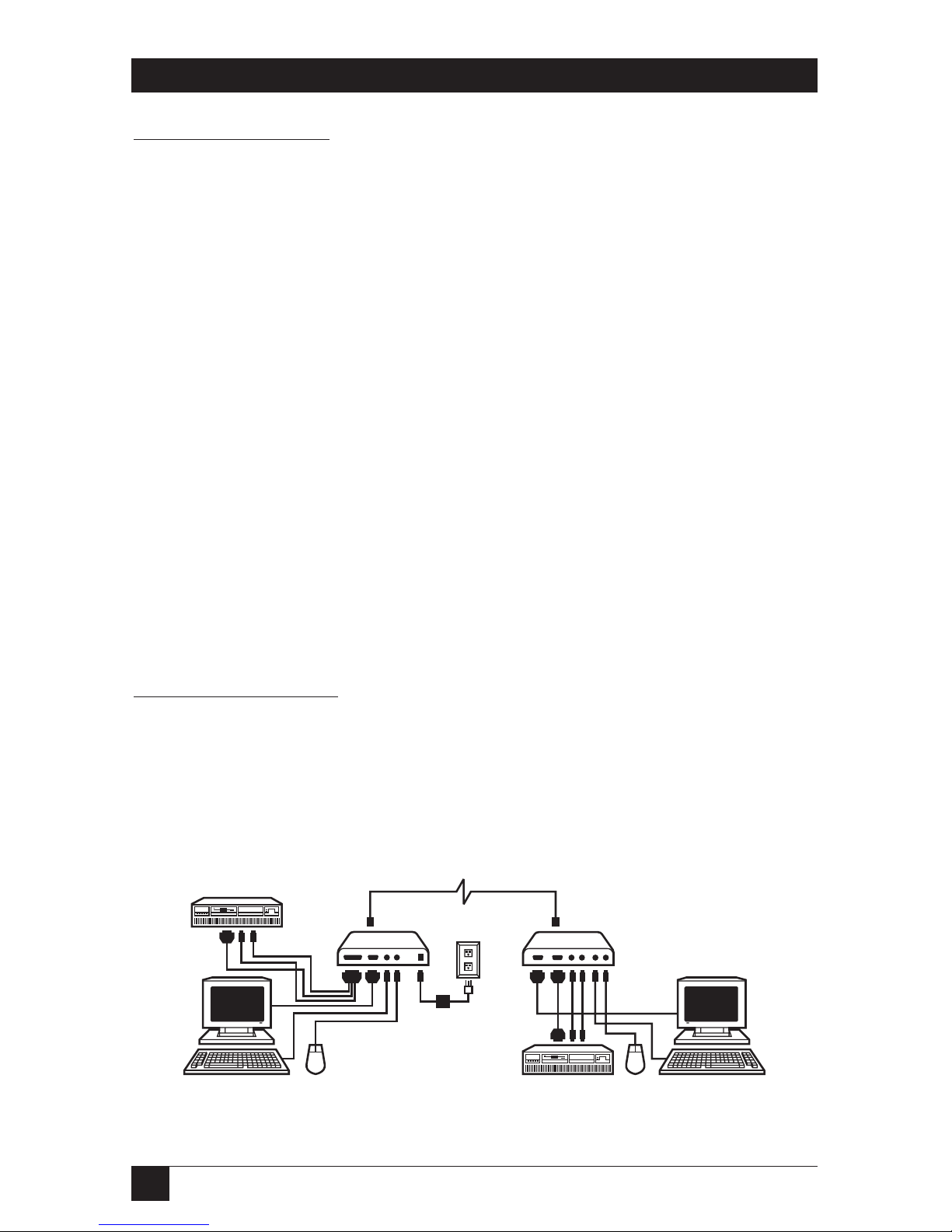
To install your Extender system, refer to the illustration below. (A Switching model
is shown; the Dual-Access model won’t have the remote CPU, and the Single-Access
model won’t have the remote CPU or the local user station.) Take these steps:
1. Use the included three-to-three extension cables to attach the CPU to the
Local Unit.
2. Dual-Access and Switching models: Plug the local keyboard, monitor, and mouse
directly into the Local Unit.
3. Plug the remote keyboard, mouse, and monitor directly into the Remote
Unit.
4. Switching models: Use the included three-to-one extension cable to attach the
CPU to the Remote Unit.
5. Connect the Local and Remote Units with straight-pinned four-pair CAT5
cable.
6. Power the Remote Unit with its included power supply.
For more information about installation, or if you’re attaching any KVM switches
to the Extender, refer to Chapter 6.
Operating the Extender
For the most part, your Extender system should operate automatically and
transparently. Some functions, though—including switching between the CPUs
with a Switching Extender—are handled with keyboard commands. Appendix C
summarizes these commands, while Section 7.3 describes them in detail.
CAT5 interconnect cable
Local
Unit
Remote
Unit
Power supply
Remote CPU
Local CPU
Local monitor,
keyboard, and mouse
Remote monitor,
keyboard, and mouse

11
CHAPTER 2: Specifications
2. Specifications
Cable Required: Between Local and Remote Units: Category 5 solid
unshielded or shielded twisted pair (UTP or STP),
wired to the EIA/TIA-568A or (preferred) -568B
standard, terminated with RJ-45 male connectors; for
pinning/pairing, see Appendix A
Compliance: CE Class B, FCC Part 15 Subpart J Class A, IC Class/
classe A
Compatibility: Video: VGA, SVGA, XGA, XGA-2, or RGB (sync on
green), although if your system has monitor ID-bit
requirements, you might need to call Black Box for
technical support;
Keyboard: IBM PC/AT or PS/2 compatible
(PC/AT types require connector adapter);
Mouse: IBM PS/2 compatible two-button, Microsoft
IntelliMouse, or Logitech PS/2 compatible 3-button
Interfaces: Video: VGA;
Keyboard and mouse: IBM PS/2 compatible;
Between units and (on ACU1049A) to remote CPU:
Proprietary composite
Video Bandwidth
(to –3 dB): Local Unit: 150 MHz;
Remote Unit: 300 MHz;
Across 100 meters (328 feet) of UTP: 95 MHz (with
equalization)
Resolution: Up to 1600 x 1280 noninterlaced at up to 60 m (200 ft.);
Up to 1280 x 1024 noninterlaced at up to 120 m (400 ft.);
Up to 1024 x 768 noninterlaced at up to 300 m (1000 ft.)
Video I/O
Signal Levels: 0.7 volts peak-to-peak
Video
Compensation: 3-stage continuously variable
Synchronization: H/V or composite, TTL signal levels; sync polarity
is preserved

12
SERVSWITCH™BRAND CAT5 KVM EXTENDER
Video Coupling: DC
Maximum
Distance: 5 m (16 ft.) from the Local Unit to the attached CPU
or KVM-switch user port;
5 m (16 ft.) from the Remote Unit to the attached
monitor, keyboard, and mouse or KVM-switch CPU
port;
300 m (1000 ft.) between Local and Remote Units;
ACU1009A only: 5 m (16 ft.) from the Local Unit to the
attached keyboard and mouse or KVM-switch CPU
port; 30 m (100 ft.) to the attached monitor;
ACU1049A only: 5 m (16 ft.) from the Remote Unit to
the attached CPU or KVM-switch user port
NOTE
With high-quality cables, it might be possible to run
farther than 5 m (16 ft.) from the Extender to attached
equipment.
User Controls: Remote Unit:
(2) Front-mounted dials: Brightness and Focus;
(3) Internal video-distance (cable-length) jumpers;
(1) Internal 4-position DIP switch for various options
Indicators: None
Connectors: On Local Unit:
(1) Front-mounted RJ-45 female for local/remote
interconnection;
Rear-mounted:
(1) HD15 male for video input from local computer;
(2) 6-pin mini-DIN female for keyboard and mouse
output to local computer;
ACU1009A and ACU1049A only:
(1) HD15 female for video output to local
monitor;
(2) 6-pin mini-DIN female for input from local
keyboard and mouse;

13
CHAPTER 2: Specifications
Connectors
(continued): On Remote Unit:
(1) Front-mounted RJ-45 female for local/remote
interconnection;
Rear-mounted:
(2) 6-pin mini-DIN female for input from keyboard
and mouse;
(1) 2.5-mm center-positive barrel jack for power;
ACU1049A only: (1) DB25 female for composite I/O
to/from the keyboard, mouse, and video ports of
the remote CPU
Temperature
Tolerance: 32 to 104˚F (0 to 40˚C)
Humidity
Tolerance: 5 to 90% noncondensing
Enclosure: Steel
Power: Local Unit:
5 VDC at up to 120 mA from CPU’s keyboard port;
Remote Unit:
From desktop power supply (certified to the relevant
international safety standards):
Input: 100 to 240 VAC at 50 to 60 Hz from utility-
power outlet, through detachable power cord
and IEC 320 male inlet, to external transformer;
Output (isolated from mains ground): 9 VDC
regulated, at up to 1 amp, from transformer
to Extender
CAUTION!
If you ever need to replace the Remote Unit’s
power supply, the replacement power supply must
have identical output characteristics. Using a
power supply with different output—even if it’s
“almost the same”—could damage your Remote
Unit and the attached equipment.
Size: 1.4"H x 8.8"W x 4"D (3.6 x 22.4 x 10.2 cm)
Weight: Shipping, complete package: Approx. 4.8 lb. (2.2 kg);
Net, each Local or Remote Unit: 1.1 lb. (0.5 kg)

14
SERVSWITCH™BRAND CAT5 KVM EXTENDER
3. Introduction
By using the Local and Remote Units that together make up the ServSwitch™
Brand CAT5 KVM Extender, you can place your VGA monitor, keyboard, and
mouse as far as 300 meters (1000 ft.) from a PC CPU. The Local and Remote Units
are interconnected with a single industry-standard Category 5 UTP or STP 4-pair
cable. All keyboard, mouse, and video signals are fully buffered to ensure
consistent remote operation of your PC.
• The Single-Access (ACU1001A) model of the Extender is designed to perform
KVM extension only.
• With the Dual-Access (ACU1009A) model, you can attach an additional
monitor, keyboard, and mouse to the Local Unit; the PC can then be operated
from either the local or remote user station (they share access on a “first-come,
first-served” basis—see Section 7.3.3).
• With the Switching (ACU1049A) model, you can attach both a monitor,
keyboard, and mouse to the Local Unit and a CPU to the Remote Unit, and
the remote user can switch between the local and remote CPUs.
The Extender is simple to operate and works with all operating systems—no
software is required. Once you’ve made sure you have everything you’ll need (see
Chapter 4) and you’ve configured all of your Extender Units (see Chapter 5), just
connect the Local and Remote Units to each other and to your equipment as
described in Sections 6.1 through 6.3, adjust your video compensation as necessary
(see Section 6.4), and you’re ready to work!
Because the Extender performs complete PS/2
®
keyboard and mouse emulation,
you can boot any attached PC without having a keyboard or mouse attached to it.
The PC(s) will boot even if no keyboard or mouse is connected to the Local or
Remote Unit.

15
CHAPTER 3: Introduction
3.1 Compatibility
The Extender is designed to operate in various environments and with a mix of
hardware from different manufacturers. During development, this product was
extensively tested with a wide variety of hardware. However, please note that it is
impossible for us to guarantee that the Extender will interoperate correctly with
every keyboard, mouse, monitor, and motherboard variant currently on the
market; if you suspect that you’re having incompatibility problems, please call
Black Box Technical Support.
In general, the Extender is compatible with the following types of equipment:
• CPU: IBM
®
PC/AT®, PS/2, and 100% compatible clones. These should be
desktop machines; laptops and docking stations are not supported.
• Monitor: VGA, SVGA, XGA, XGA-2, or RGB (sync on green). Be aware that a
few monitors and graphics cards might not work with the Extender because
they exchange monitor IDs or VESA DDC (Display Data Channel)
information. Call Black Box Technical Support for help with “ID bit”
problems. As for DDC, the Extender supports it at the local user station but
not the remote user station, so either (a) do not use a DDC monitor at your
remote station, or (b) go into the settings of each PC’s graphics card, turn
DDC off, and manually configure the card for your monitor.
• Keyboard: Standard PS/2 type (101- or 102-key) or enhanced PS/2 type
(104- or 105-key, designed for use with versions of Windows
®
starting with
Windows 95). Also supports PC/AT type keyboards with 5-pin DIN connectors,
but you’ll need keyboard and keyboard-port adapters such as our product
codes FA211 and FA212 to attach such keyboards and their native CPUs to the
Extender. Some older PC/XT™ or PC/AT type autosensing keyboards might
not be compatible with the Extender. If a keyboard or keyboard port you want
to use is some other type or has some other type of connector, call Black Box
Technical Support.
For information about keyboard typematic support, see Section 7.2.
• Mouse: Standard PS/2 type, Microsoft
®
IntelliMouse®compatible, or Logitech
®
3-button PS/2 compatible mouse and standard PS/2 type mouse ports. The
Extender is not compatible with serial mice, bus mice, or CPUs with bus-mouse
ports. If you need to attach a PC with a PC/AT type serial mouse port, run a
PS/2 mouse-extension cable to the CPU, then use a mouse-port adapter such
as product code AC244A to connect the cable to the PC’s serial mouse port.
If a mouse or mouse port you want to attach is some other type or has some
other type of connector, call Black Box Technical Support.

16
SERVSWITCH™BRAND CAT5 KVM EXTENDER
3.2 Key Features
The Extender has a number of useful features which contribute to the transparent
remote operation of your PC. Some of the more important ones are:
• Distance up to 300 m (1000 ft.)
Operate your PC from almost anywhere in the same building.
• Fully adjustable video equalization
Compensates for the loss of image quality caused by the signal passing through
such a long run of cable.
• Fully buffered signals
Remote operation of the PC is consistently smooth and transparent.
• Intelligent PS/2 keyboard and mouse emulation
With this, the PC boots and operates correctly under most circumstances, and
you can freely detach and reconnect the keyboard and mouse as necessary
(the Extender automatically initializes the keyboard and mouse as soon as it
detects that you’ve reattached them).
• Microsoft IntelliMouse compatibility
Use this and compatible “wheel mice” with confidence. On the Dual-Access
model, you can even use a standard PS/2 mouse at one user station and an
IntelliMouse at the other.
• Rackmountable
You can use our Rackmount Kit (product code RMK19U) to place Extender
Units in 1U of vertical space in a 19" rack. See Appendix B.
• Dual-Access model also supports a local station
With the Dual-Access (ACU1009A) model, you can operate the PC either
locally or remotely (but not both at the same time).
• Switching model also supports both local station and remote CPU
The Switching (ACU1049A) model not only has a local user station, it also
supports attaching a CPU to the remote unit, so that the remote user can
switch between local and remote CPUs.
We recommend that you read the remainder of this manual before you install the
Extender in order to fully familiarize yourself with the product.

17
CHAPTER 4: Checklist of System Components
4. Checklist of System Components
4.1 The Complete Package
These items should be included with your ServSwitch™ Brand CAT5 KVM
Extender package. Please contact Black Box if any are missing or damaged.
• (1) Extender Local Unit.
• (1) Extender Remote Unit.
• (1) 9-VDC 1-amp power-supply transformer and output cord.
• (1) Power-supply input cord suitable for your country or region.
• (1) Copy of this manual.
• Keyboard-, video-, and mouse-extension cabling that will run from your (local)
CPU to the Local Unit. This might be three separate cables, or it might be a
single bonded cable with three connectors at each end. In either case, the
cabling will be 5 to 6 ft. (1.5 to 1.8 m) long and will have the proper
connectors to extend PS/2 keyboard (6-pin mini-DIN male to male), PS/2
mouse (also 6-pin mini-DIN male to male), and VGA video (HD15 male to
female) interfaces.
– If your system uses 5-pin DIN keyboard connectors, you’ll also need
keyboard adapters—one of product code FA211 and one FA212—to
respectively attach (a) the keyboard to any Extender user port and
(b) the CPU’s keyboard port to the Local Unit’s CPU port.
– As mentioned in Chapter 3, the Extender doesn’t support serial mice; if
your system is designed for a serial mouse, you’ll have to attach a PS/2
mouse to the Remote Unit instead, and use an AC244A mouse-port adapter
to attach the mouse-extension cabling to one of the PC’s serial ports.
• The Switching model (ACU1049A) should also come with a 1-m (3.3-ft.) threeto-one CPU cable that will run from the Remote Unit to the remote CPU. This
cable has a DB25 male connector on the Extender end and an HD15 male and
two 6-pin mini-DIN male connectors on the CPU end.

18
SERVSWITCH™BRAND CAT5 KVM EXTENDER
4.2 The Cables You’ll Need
If you are using the Extender to get greater distance between a CPU and a VGA
monitor, PS/2 keyboard, and PS/2 mouse, your Extender package should have
included everything you’ll need except for your CAT5 cable, which you’ll have to
order separately. Read Sections 4.2.1, 4.2.3, and 4.2.5 carefully, then proceed with
Chapter 5.
If you are using the Extender to get greater distance between a ServSwitch family
KVM switch and a CPU, a user station (monitor/keyboard/mouse), or a
compatible switch, you might need additional non-included cabling. Read the
relevant sections on the next few pages, from Section 4.2.1 through Section 4.2.5.
If you are using any equipment with PC/AT style connectors, you might also
need to order some combination of these adapters:
• To attach a CPU or KVM switch with a 5-pin DIN female keyboard
connector
to the Extender: A keyboard-port adapter such as product code FA211.
• To attach a CPU or KVM switch with an RS-232 serial DB9 male mouse connector
to the Extender: A mouse-port adapter such as product code AC244A. (If the
mouse port is DB25 rather than DB9, you’ll also need an FA521A serial adapter
.)
•
To attach a keyboard or KVM switch with a 5-pin DIN male keyboard connector
to the Local or Remote Unit:
A keyboard adapter such as product code FA212.
4.2.1 TOC
ONNECT A
CPU
TO A
CPU P
ORT ON THEEXTENDER
We’ve included extension cabling with the Extender that you can use to connect
the CPU to the CPU port of a Local Unit or Switching Remote Unit. As mentioned
in the bulleted paragraphs above, you might also need port adapters if your CPU
has PC/AT type ports.
4.2.2 TOC
ONNECT ASERVSWITCHFAMILY
KVM S
WITCH TO A
CPU P
ORT ON THEEXTENDER
You would do this to extend the distance you can run from the KVM switch to a
monitor, keyboard, and mouse. (You could also do this to extend the distance you
can run between two cascaded switches, but for this to work, each switch must be
either a ServSwitch Jr. or one of the ServSwitch family models with compatible
composite interfaces listed in Section 4.2.2.B.)
The Local Unit’s CPU port consists of the HD15 female and 6-pin mini-DIN
connectors on its rear panel collectively labeled “TO CPU.” Which cables you’ll use
to connect the KVM switch to this port will depend on what type of user ports the
switch model has, as detailed in the three subsections on the next page.
 Loading...