

Page 1
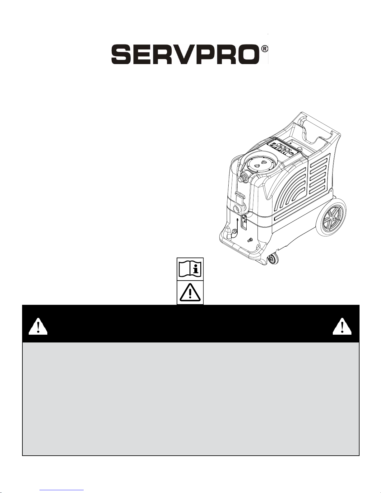
MODEL 879
EXTRACTOR
INFORMATION
&
OPERATING
INSTRUCTIONS
120V
CAUTION: DO NOT OPERATE MACHINE UNTIL YOU HAVE READ
ALL SECTIONS OF THIS INSTRUCTION MANUAL
IMPROPER USE OF THE MACHINE WILL VOID THE WARRANTY
1. Always use a defoamer when foaming occurs to prevent vacuum motor damage.
2. Connect the machine to a properly grounded outlet.
3. Keep machine from rain, snow , and extremes in temperatures. Store the machine in a
heated location. Use the machine indoors. Do not use outdoors.
4. Use approved chemicals only. NO SOLVENTS.
5. Wear gloves or use rags when removing quick disconnects to prevent burns.
6. Never use water above 130° F/54° C in the solution tank.
7. Never turn on the solution pump without your solution line connected to both the
machine and the tool.
1
3/10 revised 11/11 Form No. 56041937
Page 2

IMPORTANT SAFETY INSTRUCTIONS
This machine is only suitable for commercial use, for example in hotels, schools, hospitals, factories, shops,
and offi ces. The Advantage 1200 is not intended for normal residential housekeeping purposes.
NOTE: Read all instructions before using this machine.
When using any electrical appliance, basic precautions should always be followed, including the following
warnings
WARNING!
To reduce the risk of fi re, electric shock, or injury:
• Do not leave the machine unattended when it is plugged in. Unplug the unit from the outlet when
not in use and before servicing.
• Never turn on the solution pump without fi rst connecting either the priming hose or your solution
hose to your machine and to your tool.
• Always turn off the pump and release the pressure in the pump before disconnecting hoses
• Never add water over 130° F/54° C to the solution tank.
• Always use chemicals or water with a pH between 5 and 10.
• Extension cords must be 12/3 and no longer than 50 feet. Replace the cord or unplug immediately
if the ground prong becomes damaged.
• To avoid electric shock, do not expose to rain or snow. Use and store indoors.
• Do not allow to be used as a toy. Close attention is necessary when used near children.
• Use only as described in this manual. Use only the manufacturer’s recommended attachments.
• Do not use with damaged cord or plug. If the machine is not working as it should, has been dropped,
damaged, left outdoors or dropped into water, return it to a service center.
• Do not pull by the cord, use the cord as a handle, close a door on the cord, or pull the cord around
sharp edges or corners. Do not run the machine over the cord. Keep the cord away from heated
surfaces. To unplug, grasp the plug, not the cord.
• Do not handle the plug, the cord, or the machine with wet hands.
Do not put any object into openings. Do not use with any opening blocked; keep free of dust, lint,
hair, and anything that may reduce air fl ow.
• Keep loose clothing, hair, fi ngers, and all parts of body away from openings and moving parts.
• Do not pick up anything that is burning or smoking, such as cigarettes, matches, hot ashes, or any
health endangering dusts. Do not use to pick up fl ammable or combustible liquids such as gasoline
or use in areas where these liquids may be present.
• Turn off all controls before unplugging.
• Use extra care when cleaning on stairs.
• Connect to a properly grounded outlet only.
• Liquid ejected at the spray nozzle could be dangerous as a result of its temperature, pressure, or
chemical content.
FORM NO. 56041937 - SERVPRO 879
2
Page 3
INSPECTION:
Carefully unpack and inspect your 879 for shipping damage. Each machine is tested and inspected
before shipping. Any shipping damage incurred is the responsibility of the carrier. You should notify the
carrier immediately if you notice damage to the box, the machine, or its parts.
CLEANING SOLUTIONS:
We recommend liquid cleaning chemicals. Powder chemicals ma y be used, but unless mixed very thoroughly
they could cause a build-up in the pump, lines, and quick disconnects. Any problem caused by a chemical
build-up is not covered by warranty . Use a neutr al cleaner with a pH between 5 and 10 to avoid premature
wear of the pump, seals, and/or other components. It is a good idea to test an inconspicuous area of
the fl oor.
DANGER: DO NOT USE SOLVENTS, OR ANY CHEMICALS
THAT MAY BE FLAMMABLE, EXPLOSIVE, OR COMBUSTIBLE.
MAINTENANCE:
For optimum performance fl ush the machine with clear water at the end of each working day. Once a
month, minimum, run a fl ushing compound through the machine to break up any mineral or chemical build-
up that may have formed. The vacuum motor and the pump do not require any scheduled maintenance;
however, the motor may require replacement brushes after 1000 - 1500 hours. Clean the body with an
all-purpose detergent, and protect it with an automobile interior polish. Lubricate the wheels, castors,
and quick disconnects with an all purpose silicone spray.
PARTS AND SERVICE:
Repairs, when required, should be performed by your Servpro distributor who maintains an inventory of
original replacement parts and accessories. Call the distributor from whom you purchased this machine if
you need parts and service. Be sure to specify the machine model. Have your serial number handy.
Serial Number: __________________
Model: #879 ADVANTAGE 1200
Purchase Date:_____________
Write the name and phone number of your
distributor: _____________________________
_______________________________________
3
FORM NO. 56041937 - SERVPRO 879
Page 4
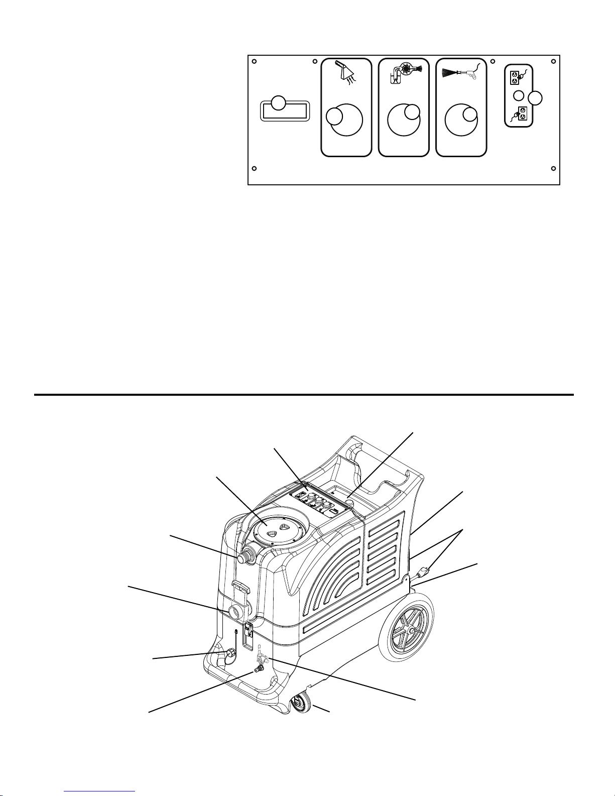
SWITCH PLATE
III
MODEL
O
O
O
MODEL (1):
This identifi es the model of your
machine.
VACUUM SWITCH (2):
This push-button switch turns
on the vacuum. The switch will
illuminate when it is on.
AUTO PUMP OUT SWITCH (3):
This switch will turn on the automatic pump-out pump and it will illuminate when it is activated.
SOLUTION PUMP SWITCH (4):
The solution pump switch will turn on the solution pump and the switch will illuminate when it is
activated. The output pressure of this pump is adjustable through the unloader valve. Refer to the
drawing below, and to the Operation Instructions.
GREEN, TWO CIRCUIT INDICATOR (5):
This light will automatically turn on when you have plugged the two power cords into separate circuits.
If this light does not turn on, try other outlets with one of the cords until the light does turn on.
NOTE: All systems in the machine may operate if this light does not turn on, but you may trip a circuit
breaker in the wall.
1
2
3
4
5
YOUR MACHINE
Vacuum Hose
Connection
Recovery
Tank
Drain
Pump-out Hose
Connection
Solution
Output
FORM NO. 56041937 - SERVPRO 879 revised 11/11
Recovery Tank
Lid
Switches
Solution Tank
Access
Auto-fi ll
Hose Connection
Power Cord
Pigtails
Pressure
Adjustment Cap
12” Wheel
Pressure Relief Valve
Castor
(inside base
compartment)
4
Page 5

SET-UP & OPERATION
1. Before each use, inspect the machine, hoses, and cleaning tools for cleanliness and completeness.
Make sure hoses are in good condition and the spray nozzle(s) is tight.
2. If not using the auto-dump feature, just make sure the brass cap is on the drain hose connector on the
front of the base of the machine.
If you choose to use the auto-dump feature, remove the brass cover on the hose connector on the
front of base of the machine, attach a hose, and place the open end of the hose in a drain. Make sure
the recovery tank drain gate is closed, and the lid is tight on the recovery tank.
3. If you choose not to use the auto-fi ll feature, just fi ll the tank with water and cleaning
chemical. Follow chemical directions regarding dilution and mixing. Do not use harsh chemicals; they
may damage seals in pumps and valves, and cause the pump to wear prematurely. .
If you choose to use the auto-fi ll feature, connect the fi ll hose to the auto-fi ll connector (located over
the solution tank fi ll hole). Turn on the water source -- HIGH PRESSURE IS NOT NECESSARY -- and
allow the tank to fi ll with water. When using the auto-fi ll system, the auto-fi ll fl oat will automatically
turn on and turn off as the tank empties and then fi lls.
NOTE: Never put water with a temperature exceeding 130
4. Pre-spray the area to be cleaned, with a pump-up sprayer, while the tank is fi lling. Follow chemical
directions.
5. Plug in the two power cords. Do not connect both cords to the same outlet. The green, ‘separate
circuit locator light (1) on the switch plate should light up. If the locator light does not come on,
check the circuit breaker box in the wall, and/or try different outlets until it does turn on. Although all
systems in the machine may work correctly if you are not on two circuits, a circuit breaker in a wall
panel may trip. If you make sure the green light is turned on, you will prevent tripped circuit breakers.
°
F / 54 °C in the solution tank
6. Prime the 1200 psi pump: fi ll the solution tank with water, if not already done, and turn on the pump.
You may notice a ‘tone’ change in the sound of the pump (smoother, with less of a rattle).
CAUTION -- NEVER TURN ON THE SOLUTION PUMP BEFORE CONNECTING YOUR
SOLUTION LINE TO YOUR MACHINE AND TO YOUR TOOL. If the pump builds pressure
before you connect the hose and tool, you will not be able to connect them.
7. Use defoamer to prevent foam.
8. Attach the solution spray hose to the solution quick disconnect. Attach the vacuum hose to the hose
barb on the front of the recovery tank. Connect the other ends of the hoses to the tool.
9. Turn on the vacuum (2) and turn on the dump pump (3). Begin spraying.
10. When the job is fi nished, turn off the water source. Vacuum the remaining solution from the solution
tank into the recovery tank.
11. Run a few gallons of clean water through the system. Drain the recovery tank by opening the drain
gate over a bucket or drain. Disconnect the hoses from the cleaning tool.
12. Unplug the power cords.
13. Clean the machine and the tool. Never store your machine outside, and keep it from extremes in tem-
peratures.
NOTE: if the green, circuit locator light does not illuminate when the cords are plugged in, then both cords
are on
the same circuit. Try other outlets with one of the cords until you get the locator light to come on.
NOTE: if the heat switch is turned on when both cords are on the same circuit, the breaker in the wall may
trip.
5
FORM NO. 56041937 - SERVPRO 879
Page 6
AUTO VACUUM SHUTOFF:
When the recovery tank is full, the ball fl oat will shut-off the suction to prevent the machine from
overfl owing. NOTE: the fl oat may not work if there is foam in the tank. Always use defoamer to
prevent overfl ow.
AUTO-FILL
1 Operation:
• Attach a 3/4” garden hose to the auto-fi ll valve, and connect the other end of the hose to your water
source.
• Make sure the fl oat that hangs from the auto-fi ll valve into the tank is free of obstruction and can
move freely.
• Turn the water supply on.
• The auto-fi ll fl oat will automatically shut-off the fl ow of incoming water when the solution tank is
nearly full, and it will allow the valve to open again once the water level has dropped to a predeter
mined level.
AUTO-DUMP
1 Operation:
• Before each use: if necessary, unscrew the stainless steel fi lter at the bottom of the recovery
tank and clean it. Also make sure the fl oat in the recovery tank is clean.
Attach a 3/4” garden hose to the dump pump outlet fi tting on the back of the base of the
•
machine.
Run the other end of the hose into a drain.
•
Turn ON the dump pump switch (switch is located on the switch panel on the top of the machine).
•
• NOTE: the dump pump is ‘self-priming.’ You should see water start to fl ow within 30 seconds of
the pump turning on. If water does not begin to fl ow, check the fi lter to see if it is plugged with
debris.
• After each job: run clear water though the dump pump to wash out any chemical residue.
Remove and clean the stainless steel fi lter in the back of the tank. Reinstall the fi lter once it is
clean. Clean and empty the recovery tank.
CAUTION: Use care when handling hazardous chemicals.
CAUTION: Never leave the machine running when you are not actively using it.
CAUTION: always use a defoamer in the recovery tank to prevent water or foam
from entering the vacuum motor.
CAUTION: Always make sure the fl oat cage is clean and the ball can
travel freely before turning on the machine.
FORM NO. 56041937 - SERVPRO 879
6
Page 7
22
23
24
22A
29
32A
32
34B
34
28
36
25
34A
35
33
55
37
38
49
40A
48
54
63
243
1
67
40
64
39
41
45
42
43
44
120V
#879
70
46
69
21
10A
10B
13
11
10
12
14A
2
14
18
16
15
17
28
65
28
56
61
60
47
50
57
53A
O
O
O
62
53
59
58
52
4
3
2
11
68A
1
8
7
6
68
7
FORM NO. 56041937 - SERVPRO 879revised 11/11
Page 8

Model 879
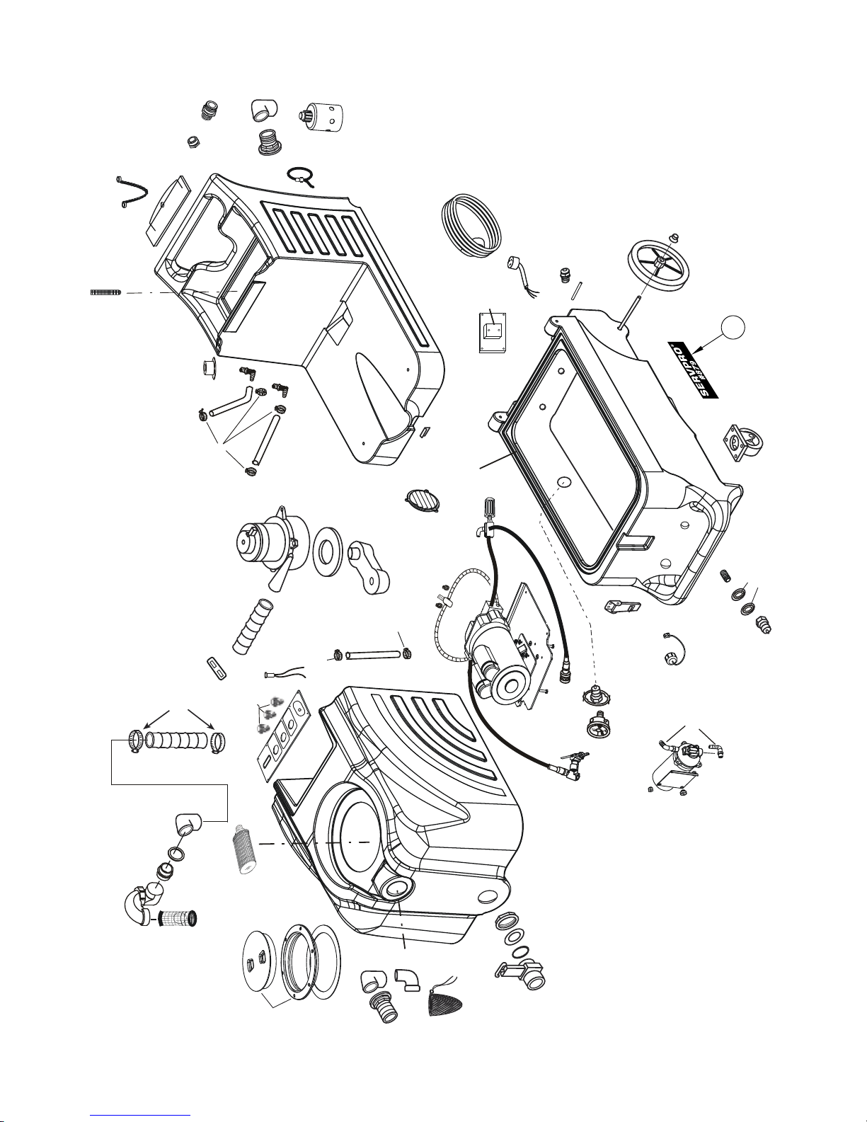
Item Ref. No. Qty Description
1# 903USP 1 Drain Gate
2
# 187USP 1 O-Ring
3 187B 2 Washer, rubber
# 185USP 1 Nut, 1-1/2”
4
6 907 1 Hose Barb, vacuum inlet
7 1074 1 Gasket
8 2086A 1 Lid with Ring, 6”
56380968 1 O-Ring for 2086A Lid
10 929B 1 Ball Float, vac shut-off
10A 1154A 1 Adapter, ABS trap
10B 1154 1 Adapter, ABS
11
# 922USP 2 Elbow, PVC, FPT
# 156USP 2 Hose Clamp
12
13 430 25.5” Hose, vacuum, 2”ID X 25.5”
14 430A 1 Hose, vacuum, 2”ID X 13.5”
14A 4404C 1 Bar, vacuum hose hold-down
15 2167 1 Switchplate, Advantage
[ ] 2167-1200 1 Overlay
16 1623R 3 Switch, push-button, ON/OFF
17 227 1 Green light
18 2069B 1 Filter, inlet 30 mesh
21# 31USP 1 Washer, brass
22 1184 1 Adaptor, garden hose
22A 1310A 1 Valve, water inlet
23 1533 1 Connector, hose adaptor
24 1534 1 Elbow, 1” 90º
25 1571 1 Bushing, 1” x 1/2” PVC
28# 166USP 4 Hose Clamp
29 1557A 1 Screen, fi lter
32 2175 1 Lid, Solution tank
32A# 805USP 1 Chain, 8”
33 TKC-11 1 Solution tank
34 946 1 Hose, pump inlet, 1/2” ID X 15”
34A 2176 1 Elbow, 1/2” ID, 90º
34B 2177 1 Grommet, rubber
35 925 1 Hose, pump bypass, 3/8” ID X 13”
36 408G 1 Vacuum, 3-stage
Item Ref. No. Qty Description
37 2013 1 Gasket, vacuum
38 MA-6 1 Manifold, vacuum
39# 230USP 2 Retainer, cord pigtail
40 2154 2 Pigtail, power cord
40A 2155 2 Power cord, 25 ft
41 801 2 Hinge pin
42# 910-1863 1 Axle rod, 18.63”
43 2092 2 Wheel, 12 inch
44# 27AUSP 2 Axle cap
45 MPE-3 1 Base, complete
46# 905USP 2 Castor
47
# 56471194 1 Latch
48 909A 1 Catch, for latch
# 459USP 1 Louver, 2-1/2”
49
50# 45USP 1 Quick disconnect
52 VT-35 1 Recovery tank
53# 2166 1 Pressure gauge
53A# 219USP 1 Quick disconnect
54 FP228A 1 Gasket, 78.5”
55 1603 2 Strap, cord wrap
56 FP630 1 Hose assy, pump intake
57 237 1 Cap with chain, drain hose
58 2067 1 Pump, dump
59 1546 2 Hose barb, two per bag
60 FP636 1 Motor, no pump
61 FP657 1 Pump, complete, no motor
62 FP632 1 Hose, unloader to outlet
63 FP633 1 Unloader valve assembly
64 FP631 1 Hose, pump to gauge
65 946 1 Hose, dump pump inlet, 32”
67 4405A 1 Relay, 25 AMP
68 FP619 1 Pre-fi lter bag
68A 1140 1 Elbow, 90°, ABS
69# 92AUSP 1 Nipple, s/s
70# 2195 2 Label Servpro
[ ] 1093A 1 Label Warning
[ ] 4344 1 Label Gauge Priming Warning
FORM NO. 56041937 - SERVPRO 879 revised 11/11
* FP618 Pump and motor, complete
* 1160K Pump rebuild kit, valves & O-rings
* 1160A Pump rebuild kit, plunger and seals
* = Optional, Not Included
[ ] = Not Shown
# = Revised or new since last update
8
Page 9
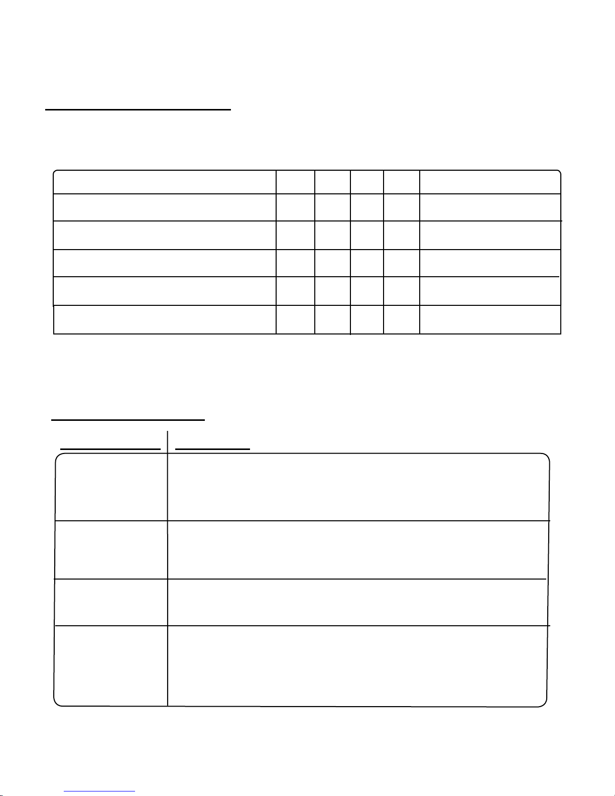
MAINTENANCE SCHEDULE
MODEL #879
CLEAN ALL FILTERS
CHECK POWER CORD
FLUSH OUT with DE SCALER
REPLACE VAC MOTOR BRUSHES
REPLACE PRESSURE REGULATOR
REBUILD PUMP
TROUBLE SHOOTING:
IF THIS OCCURS CHECK THIS
NO SPRAY
Solution tank is empty, or fi lter is plugged up.
Clogged spray tip.
Pump not running.
Valve on wand not operating.
Solution hose not completely connected to hose or to machine.
DAILY
X
X
WEEKLY
MONTHLY
X
YEARLY
X
OTHER
Around 1500 hours
Or as needed
Around 1500 hours
This pump motor runs on DC voltage, and it should start running as soon as you
PUMP DOES NOT RUN
LOW SUCTION
NO SUCTION
turn on the switch. If the pump motor does not start running, check the wiring to
the switch, to the bridge rectifi er, and to the motor. Check the switch to see if it is
‘open.’ Measure the DC voltage out of the bridge rectifi er (should be about 100V).
Debris is plugging cleaning tool or vacuum hose.
Drain gate is not completely closed, or seals are damaged.
Recovery Tank lid is not closed completely or is damaged.
Ball in the fl oat is blocking air fl ow. Turn off the vacuum so the ball will drop down.
No power to motor. Does the switch light up? If not, the switch may be bad or
there may be no power getting to the switch. Check wiring connections.
Test the switch with a volt/ohm meter.
Test the vacuum motor by connecting it directly to AC.
9
FORM NO. 56041937 - SERVPRO 879
Page 10

NOTES:
MODEL #879
SERVPRO INDUSTRIES, INC.
575 AIRPORT BLVD.,
GALLATIN, TN 37066
615-451-0200
 Loading...