

Page 1
CDHD Servo Drive
User Manual
Revision 0.2
PRELIMINARY RELEASE
Page 2

Page 3

CDHD
User Manual i
Revision Histo r y
Document
Revision
Date Remarks
0.2 June 2011
Added diagram: CDHD-1D5 Dimensions;
Replaced diagram: Syste m Wiring - Pin
Assignments; Minor text fixes
0.1 June 2011 Preliminary version
Hardware
Revision
Firmware
Revision
Software
Revision
Remarks
0.0.0.10
Important Notice
© 2011 Servotronix Motion Control Ltd.
All rights reserved . No par t of this work may be repr od uced or transmitted in any
form or by any mean s without prior wr itten permiss ion of Servotr onix Motion
Control Ltd.
Disclaimer
The information in this manual was accurate and reliable at the time of its
release. Servotronix Motion Control Ltd. reserves the right to change the
specifications of the product described in this manual without notice at any time.
Trademarks
All marks in this manual are the property of their respective owners.
Contact Information
Servotronix Motion Control Ltd.
21C Yagia Kapayim Street
Petach Tikva 49130
Israel
Tel: +972 (3) 92 7 3800
Fax: +972 (3) 922 8075
Website:
www.servotronix.com
Technical Support
If you need assistance with the installation and configuration of the CDHD drive,
contact Servotronix technical support:
tech.support@servotronix.com
Customer Service
Servotronix is committed to delivering quality customer service and support for
all our products. Our goal is to provide our customers with the information and
resources so that they are available, without delay, if and when they are needed.
In order to s erve in the most effective way, we recommend that you contact
your loca l sales representative for order status and del ivery informa tion, product
information and literature, and application and field technical assistance. If you
Page 4
CDHD
ii Servotronix
are unable to contact your local sales representative for any reason, please use
the most relevant of the contact details below:
For technical support, contact:
tech.support@servotronix.com
To order products, contact:
orders@servotronix.com
For all other inquiries r egarding CDHD drives or other Serv otronix products,
contact: customer.service@servotronix.com
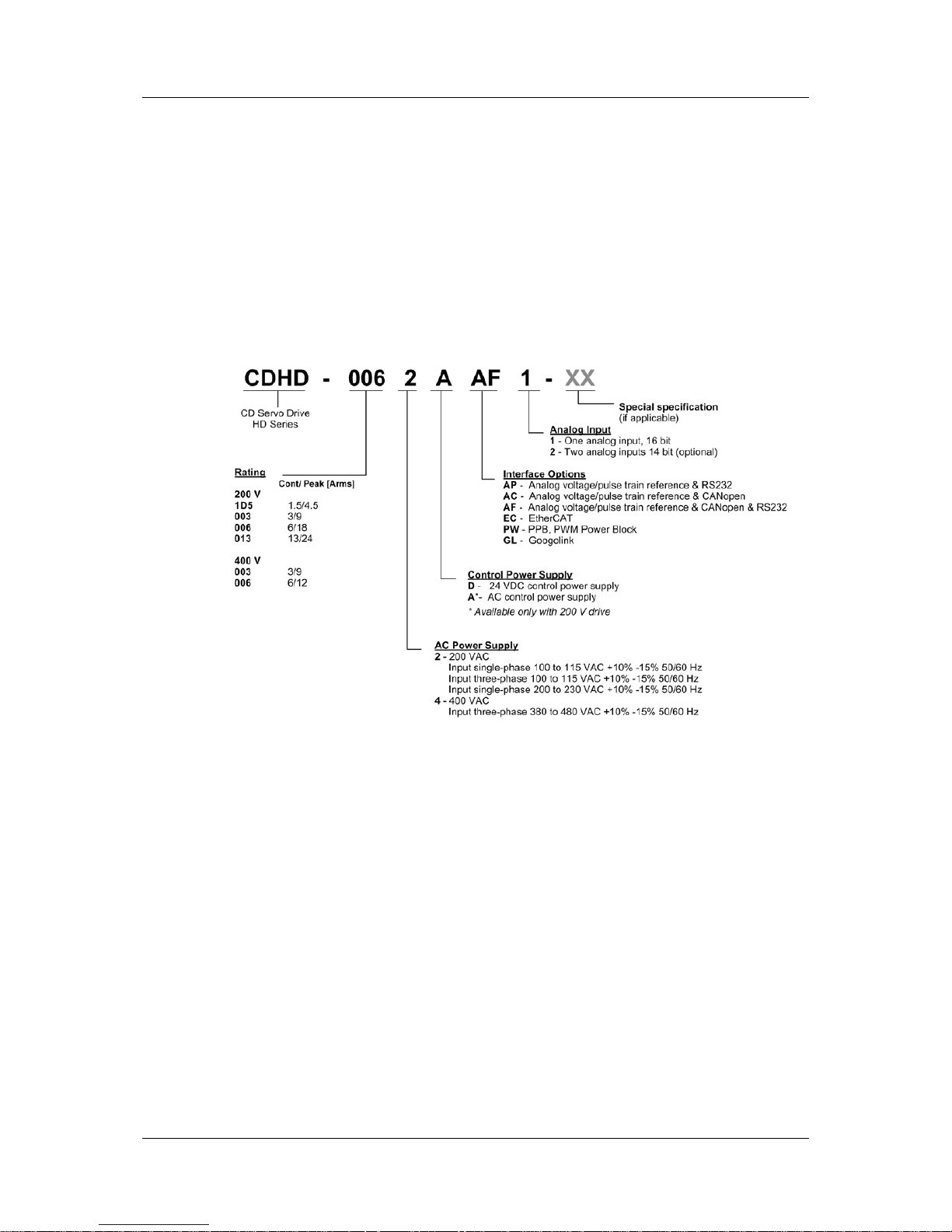
Part Number
For ordering the CDHD, r e fe r to the followin g diagram:
Warranty
The warranty is valid for 12 months from the date of shipment and applies only if
material or workmanship is found to be defective. The warranty will be invalid if
the customer fails to install, operate or maintain the product in accordance with
the instructions in this user manual.
During the warranty period, the owner must pay the cost of shipping the product
to the factory for repair , and Servotronix will pay for shipping the repaired
product to the customer.
After the warranty period has expired, all shipping costs will be the responsibility
of th e cust o mer.
Before returning the product, the customer must first request a Return Materials
Authorization (RMA) number from Se rvotronix by email to rma@servotronix.com
The complete Warranty Statement can be found in the Terms and Conditions
document on the Servotronix website:
www.servotronix.com/customer-service.html
Page 5

CDHD
User Manual iii
Contents
1 Introduction ________________________________________________ 1
1.1 Documentation .......................................................................................... 1
1.1.1 About This Manual ............................................................................ 1
1.1.2 Documentation Set for CDHD ............................................................. 1
1.2 Safety ...................................................................................................... 1
1.2.1 Safety Sy mb o ls ................................................................................ 1
1.2.2 Safety Instructions ........................................................................... 2
1.3 Standards Compliance ................................................................................ 2
1.3.1 General Information ......................................................................... 2
1.3.2 CE Compliance ................................................................................. 3
1.4 Unpacking................................................................................................. 4
2 Product Descri p t ion __________________________________________ 5
2.1 Overview .................................................................................................. 5
2.1.1 General Description .......................................................................... 5
2.1.2 Product O pt ions ............................................................................... 5
2.2 Technical Specifications .............................................................................. 6
2.2.1 Dimensions ..................................................................................... 6
2.2.2 Mechanical and Electrical Specific a tions - 200V .................................... 7
2.2.3 Mechanical and Electrical Specific a tions - 400V .................................... 8
2.2.4 Control Specificati ons ...................................................................... 10
2.2.5 Protective Functions and Environment................................................ 11
2.2.6 Communication ............................................................................... 11
2.2.7 I/Os............................................................................................... 12
2.2.8 Motor Feed back............................................................................... 13
2.3 System Wiring - Pin Assignment s ................................................................ 14
3 Installation ________________________________________________ 15
3.1 Installation Overview ................................................................................ 15
3.2 Preparation .............................................................................................. 15
3.2.1 Hardware Requ irem ents ................................................................... 15
3.2.2 Computer Requirements................................................................... 16
3.2.3 Electrical Requirements .................................................................... 18
3.3 Mecha nic al Installation .............................................................................. 20
3.3.1 Mount th e CDHD ............................................................................. 20
3.4 Electr ical Installat io n ................................................................................. 20
3.4.1 Connect Motor (P2) ......................................................................... 20
3.4.2 Connect STO (P1)............................................................................ 21
3.4.3 Connect Regen (P3) ......................................................................... 22
3.4.4 Connect Motor Feedback (C4) ........................................................... 22
3.4.5 Connect Controller I/Os (C2) ............................................................ 24
3.4.6 Connect Machine I/Os ( C3) ............................................................... 25
3.4.7 Connec t AC I nput Voltage (P4).......................................................... 26
3.5 Set the Drive Address................................................................................ 27
3.6 Connect to PC ( C1 or C7) ........................................................................... 28
3.7 Power Up ................................................................................................. 29
3.8 Servo Studio So f tware In stallation ............................................................... 29
4 Configurati on and Operation___________________________________ 30
4.1 Variables and Commands........................................................................... 30
4.2 ServoSt ud io Software ................................................................................ 30
4.3 Connecti ng to a Drive ................................................................................ 31
4.4 Enabling/Disabling a Drive ......................................................................... 31
4.4.1 Drive Enable ................................................................................... 31
4.4.2 Operation Mod e Code s ..................................................................... 32
Page 6

CDHD
iv Servotronix
4.5 Managing Drive Parameters ....................................................................... 33
4.6 Config uring Para m eters Using Serv o S tudio .................................................. 34
4.6.1 Tuning a nd Te sting .......................................................................... 34
4.6.2 Drive Info ....................................................................................... 35
4.6.3 Power ............................................................................................ 35
4.6.4 Motor ............................................................................................. 35
4.6.5 Foldback ........................................................................................ 35
4.6.6 Units.............................................................................................. 35
4.6.7 Feedback ....................................................................................... 35
4.6.8 Motion ........................................................................................... 36
4.6.9 Scope ............................................................................................ 36
4.6.10 Digital I/Os ..................................................................................... 36
4.6.11 Analog I/O...................................................................................... 36
4.6.12 Enable ........................................................................................... 36
4.6.13 Current Loop .................................................................................. 36
4.6.14 Current Limits ................................................................................. 36
4.6.15 Velocity L oop .................................................................................. 36
4.6.16 Velocity Limits ................................................................................ 36
4.6.17 Terminal ........................................................................................ 36
4.6.18 Faults ............................................................................................ 37
4.6.19 Parameters Table ............................................................................ 37
4.7 ServoStudio Expert View ........................................................................... 37
5 Firmware Upg ra d e __________________________________________ 38
5.1 Preparation .............................................................................................. 38
5.2 Upgrade Procedure ................................................................................... 38
6 Troubleshooting ____________________________________________ 39
6.1 Drive Status 7-Segment Display ................................................................. 39
6.2 Faults a nd Warning s .................................................................................. 39
6.3 Status Information in ServoStudio .............................................................. 40
6.4 Fault and Status Queries ........................................................................... 40
6.5 Fault Codes and Names ............................................................................. 40
Page 7

CDHD Introduction
User Manual 1
1 Introduction
1.1 Documentation
1.1.1 About This Manual
This manual describ e s t he Servotronix CDHD Servo Drive. It provides th e
information required for installation, configuration and basic operation of the
CDHD unit.
This document is intended for persons who are qualified to transport, assemble,
commission, and maintain the equipment described herein.
1.1.2 Documentation Set for CDHD
This manual is part of a documentation set. The entire set consists of the
following:
CDHD Quick Start Guide. Basic setup and operation of the drive.
CDHD User Manual. Hardware installation, configuration and operation.
CDHD VarCom Reference Manu al. Parame ters and commands used to
program the CDHD.
1.2 Safety
Only qualified persons may perform the installation procedures . You do not need
to be an expert in motion control to install and operate the drive system.
However , yo u m us t ha ve a basic under standi ng of electronics, computers,
mechanics, and safety practices.
The CDHD utili zes ha zardous volt ag es.
Be sure the driv e is properly grounded.
Before you install the CDHD, review the safety instructions in this manual.
Failure to follow t he sa fety inst r uctions may result in personal injury or
equipment damage.
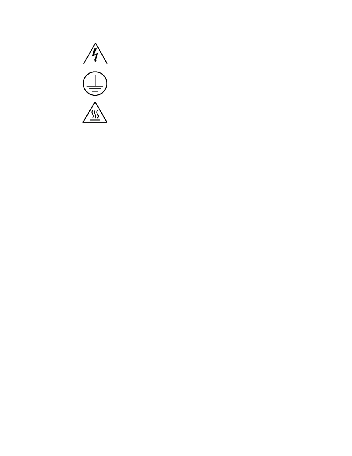
1.2.1 Safety Symbols
Safety symbols indicate a potential for personal injury or equipment damage if
the recommended precautions and safe operating practices are not followed.
The following safety-a lert symbols are used on the drive and in the
documentation:
Caution ISO 7000-0434 (2004-01)
Page 8
Introduction CDHD
2 Servotronix
Warning. Dangerous voltage. IEC 60417-5036 (2002-10)
Protective earth; protective ground IEC 60417–5019 (2006-08)
Cautio n, ho t su rf ac e IEC 60417-5041 (2000-10)
1.2.2 Safe ty Instructions
Read all available product documentation before assembling and
commission ing. I ncor re ct ha ndl i ng of this produ ct may ca u se pe rso na l inj ury
and/or damage to equipment. Ad he re strict ly to the insta l lation instruc tions
and requirements.
All syste m c omponents must be connected to ground. Electrica l safety is
provided through a low-resistance earth ground connection.
This product contains static sensitive components that can be damaged by
incorr ect hand l ing . Av oid conta ct with h ig h insulati ng m ateria ls (artif ic ia l
fabrics, plastic film, etc.). Place the product on a conductive surface. Ground
yourself (discharge any possible static electricity build-up) by touching an
unpainted, metal, grounded surface.
Keep all cov ers and cabinet d oors shut during operation. Otherwise,
potential hazards may cause personal injury and/or damage to equipment.
During operation the product has electrically charged components and hot
surfaces. The heat sink can reach temperatures of 90°C. Control and power
cables can carry a high voltage, even when the motor is not rotating.
To avoid electric arcing and hazards to personnel and electric contacts,
never disconnect or connect the product while the power source is
energized.
After removing the power source from the equipment, wait at least
5 minutes before touching or disconnecting sections of the equipment that
normally carry electrical charges (e.g., capacitors, contacts, screwed
connections). For safety, measure the electrical contact points with a meter
before touching the equipment. Wait until the voltage drops below 30 VAC
before handling components.
1.3 Standards Compliance
1.3.1 General Information
The CDHD has been successfully tested and evaluated according to standards
IEC 61800-5-1 and UL 508C. This testing outlines the minimum requirements for
electrically operated power conversion equipment (frequency converters and
servo amplifiers) , whi ch are intended to eliminate the risk of fire, electric shock,
or injur y to persons.
Page 9

CDHD Introduction
User Manual 3
UL 508C references UL 840, which describes the achievement by design of air
and insulation creepage spacings for electrical equipment and printed circuit
boards. The CDHD provides overload prot ection and current limit control .
The drive is i ntended for operation in pollution level 2 environment.
The terminals on the controller are coded so they can easily be identified in the
instructions. The instructions identify the connections for the power supply, load,
control, and ground.
Integral solid state short circuit protection does not provide branch circuit
protection. Branch circuit protection must be provided in accordance with the
National Electrical Code and any additional local codes, or the equivalent.
1.3.2 CE Compliance
Compliance with EC EMC Directive (2004/108/EC) and EC Low Voltage Directive
(2006/95/EC) is mandatory for all servo drives provided to the European
Community. CDHD is manufactured in conforman ce with these directives. CDHD
drives have also been successfully tested and evaluated to the limits and
requirements of these directives.
EC Low Voltage Directive (2006/95/EC) complies with standard IEC 61800-5-1.
The following standards are used in connec tio n with EC EM C Dir e ctive
(2004/108/EC):
IEC 61000-6-1/2 (Interference Immunity in Residential & Industrial Areas)
IEC 61000-6-3/4 (Interference Generation in Residential & Industrial Areas)
Drives are components that ar e intended for incorpora tion into a m achine, for
industrial use. Before a drive is in installed, verify that the associated equipment
complie s with the following standards :
EC Machinery Directive (2006/42/EC)
EC EMC Directive (2004/108/EC)
EC Low Voltage Directive (2006/95/EC)
Standards EN/IEC 60204-1 (Safety and Electrical Equipment in Machines),
ISO 12100 (Safety of Machines) and EN 292 must be observed in reference to
Machinery Directive (2006/42/EC) .
Standard IEC 6 04 39-1 (Low-voltage Switchgear and Control Gear Assemblies)
must be observed in reference to EC Low Voltage Directive (2006/95/EC).
The machine manufacturer must generate a hazard analysis for the machine,
and must implement suitable measures to ensure that unexpected movements
will not c a use perso nal inju ry and/or property damage.
The machine manufacturer is responsible for ensuring that the machine meets
the requirements specified by the EMC regulations. Guidelines for correct
installation for EMC (such as shielding, grounding, treatment of connectors and
cable layout) are provided in this.
The machine manufacturer must check whether EC Directives or other standards
must be applied to the machine.
Servotronix only guarantees the conformance of the servo system with the
standards cited i n this chap ter.
Page 10

Introduction CDHD
4 Servotronix
Caution: Installa tion of the e quipment is crit ic a l in designi ng sy s te m and
machine electromagnetic compatibility (EMC).
The end us er must appl y the installation rec o mmenda tions in th is m anual.
1.4 Unpacking
1. Open the package(s) and remove all packing materials and items. The
package contai ns two items:
• The CDHD drive
• A p a ck et of mating conn ectors for the power connect ors .
2. Check to ensure there is no visible damage to any of the equipment. If
damag e is d etected, notify th e carrier im m e d iately.
Page 11

CDHD Product Description
User Manual 5
2 Product Description
2.1 Overview
2.1.1 General Description
The CDHD is a full-featured, high-performance servo drive featuri ng in novativ e
technologies and industry-leading power density.
Key features of the CDHD include:
Support for rotary and linear brushless DC motors, and DC brush motors.
Operation in current, velocity and position control loops.
Eleven digital inputs, six digital outputs, together with an analog input and
output, to meet any I/O requirement.
Various communication options.
Various motor feedback options.
Fir mware customization to address special application requirements.
OEM motors predefined in user interface to enable immediate integration.
2.1.2 Product Options
The CDHD product family offers a number of options :
200 or 400 VAC rating
Contin uous current of 1.5, 3, 6 or 13 A rms for the 200 V model s
Continuous current of 3 or 6 A rms for the 400 V m odels
One 16-bit or two 14-bit analog inputs
Various interface options, including analog voltage/pulse train and CANopen.
Refer to the part number diagram at the beginning of this manual for the various
ordering options for the CDHD drive.
Page 12
Product Description CDHD
6 Servotronix
2.2 Technical Specifications
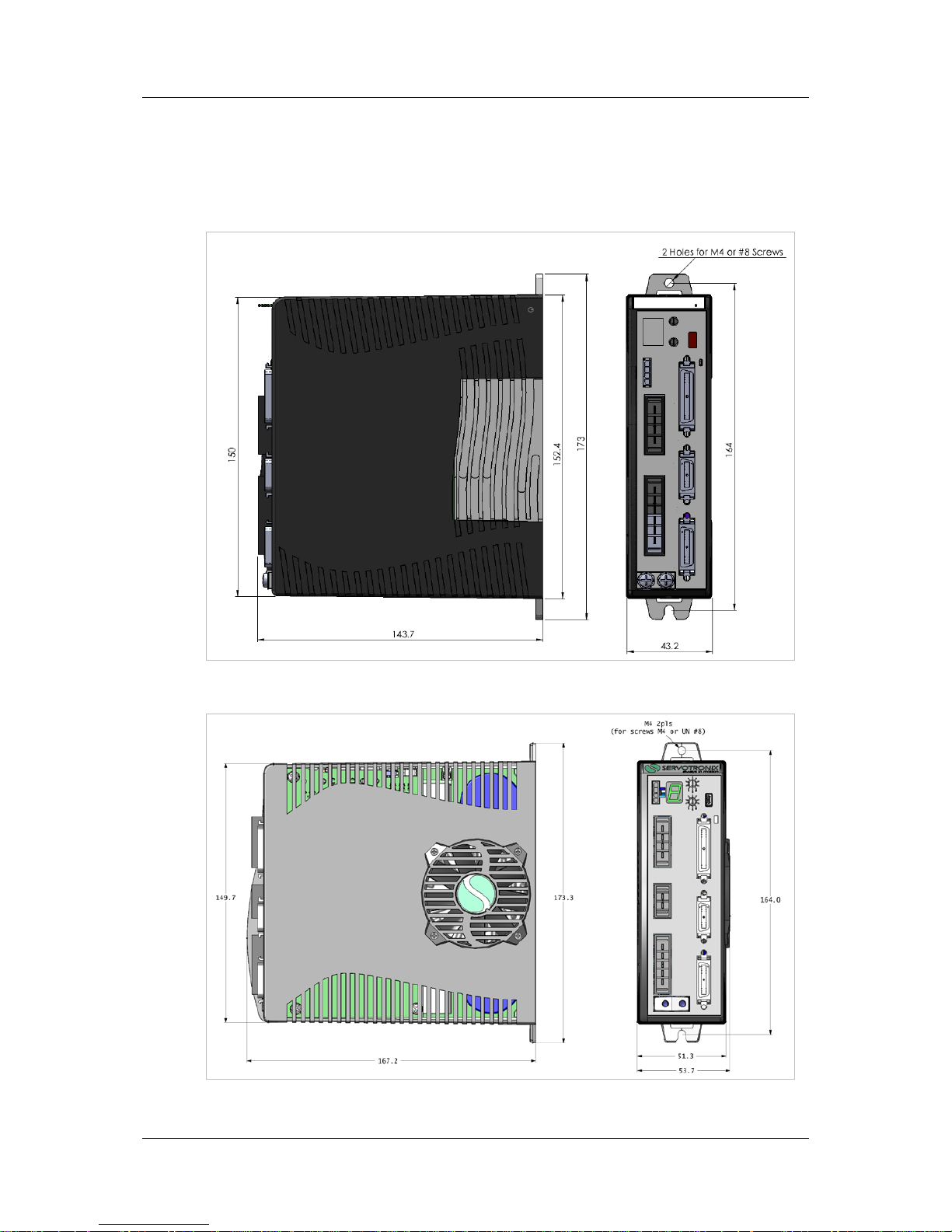
2.2.1 Dimensions
The exterior dimensions of the CDHD-1D5 and CDHD-006 are shown in
Figure 2-1 and Figure 2-1, respectively
Figure 2-1. CDHD-1D5 Dimensions (in mm)
Figure 2-2. CDHD-006 Dimensions (in mm)
Page 13

CDHD Product Description
User Manual 7
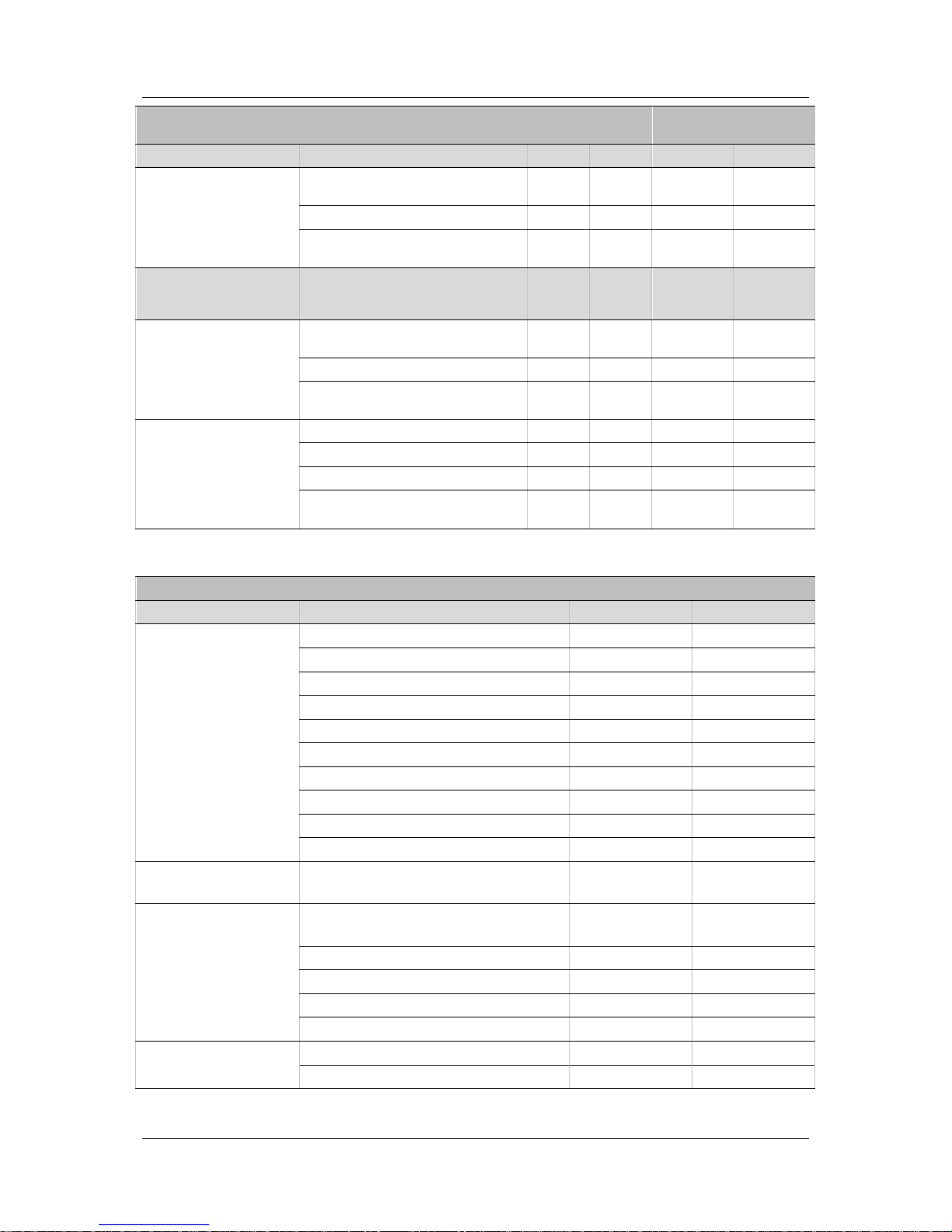
2.2.2 Mechanical and Electrical Specifications - 200V
Single a nd ThreePhase 200V
Specification
CDHD1D5
CDHD003
CDHD006
CDHD013
Ratings
Input Power Main Circuit
(L1, L2, L3 )
Voltage (VAC Line-Line) Nominal
±10%
110 to
230
110 to
230
110 to 230 110 to 230
115 VAC 1 Phase 1 Phase
1 Phase or
3 Phase
1 Phase or
3 Phase
230 VAC 1 Phase 1 Phase 1 Phase 1 Phase
Line Frequency (Hz) 47-63 47-63 47-63 47-63
KVA at 115 VAC
KVA at 230 VAC
Continuous Current (A)
Peak Current (A) f or 2 sec
Withstand Voltage (Primary to
Ground)
Line Fuses (FRN -R, LPN, or
equivalent)
Logic Input Power
(L1C, L2C)
115 or 230 VAC 1 Phase 1 Phase 1 Phase 1 Phase
Motor Output
(U,V,W)
Continuous Output Current (A rms) 1.5 3 6 13
Continuous Output Current (A
peak)
2.12 4.24 8.485 18.38
Peak Output Current (A rms) f or
2 sec
4.5 9 18 26
Peak Output Current (A peak) for
2 sec
6.3 12.72 25.455 36.76
PWM Frequency (kHz) 16 16 16 8
Soft Start Max. Surge Soft Start Current (A) 6
Max. Charge Time (ms) 250
Hardware
Unit Weight (kg) 0.9
Connection Hardw are PE Ground Screw Size/ Torque
M4/
1.35 Nm
Wire Size
Control Circuit (AWG ) u p to 3
meter
24-28
Main Circuit Motor Lines (AW G ) 14-16
Main Circuit AC Inputs (AWG) 14-16
PE Ground Screw 14
Clearance Distance Side-to-Side (mm) 10-15
Top/Bottom (mm) 50
Voltage Trip
Under-Voltage Trip (nominal)
(VDC)
100
Over-Voltage Trip (VDC) 420
Page 14
Product Description CDHD
8 Servotronix
Single a nd ThreePhase 200V
Specification
CDHD1D5
CDHD003
CDHD006
CDHD-
013
Power Temperature
Power Over-Temperature Warning
(°C)
100
Power Over-Temperature Fault (°C) 110
Trigger Temperature for Highspeed Fan (°C)
NA NA 60
Regen External
Regenerative resistor
(B1+, B2)
External Shunt
Regulator
Peak current (A) NA NA 30
Minimum resistance (Ω) NA NA 13.1
Watts NA NA
system
dependent
Application Informat ion Capacitance (F) NA NA 1120
Bus Voltage (nominal) (VDC) NA NA 320
VHYS (Regen Circuit Turn-off) VDC) NA NA
VMAX (Regen Circuit Turn-on)
(VDC)
NA NA
2.2.3 Mechanical and Electrical Specifications - 400V
Three-Phase 400V Specification CDHD-003 CDHD-006
Ratings
Input Power Main Circuit Voltage (VAC Line-Line) Nominal ±10 % 530-600 530-600
(L1, L2, L3 ) 380 VAC 3 Phase 3 Phase
430 VAC 3 Phase 3 Phase
Line Frequency (Hz) 47-63 47-63
KVA at 380 VAC
KVA at 430 VAC
Continuous Current (A)
Peak Current (A) f or 2 sec
Withstand Voltage (Primary to Ground)
Line Fuses (FRN -R, LPN, or equivalent)
Logic Input Power
(L1C, L2C)
VDC 24 VDC ±10% 24 V DC ±10%
Motor Output
(U,V,W)
Continuous Output Current (A rms) 3 6
Continuous Output Current (A peak) 4.24 8.485
Peak Output Current (A rms) for 2 sec 9 18
Peak Output Current (A pe a k ) f or 2 sec 12.72 25.455
PWM Frequency (kHz) 16 16
Soft Start Max. Surge Soft Start Current (A)
Max. Charge Time (ms)
Page 15

CDHD Product Description
User Manual 9
Three-Phase 400V Specification CDHD-003 CDHD-006
Hardware
Unit Weight (kg)
Connection Hardw are PE Ground Screw Size/Torque
Wire Size Control Circuit (AWG) up to 3 meter
Main Circuit Motor Lines (AW G )
Main Circuit AC Inputs (AWG)
PE Ground Screw
Clearance Di st a nce Side-to-Side (mm)
Top/Bottom (mm)
Voltage Trip
Under-Voltage Trip (nominal) (VDC)
Over-Voltage Trip (VDC)
Power Temperature
Power Over-Temperature Warning (°C)
Power Over-Temperature Fault (°C)
Trigger Temperature for High-speed Fan
(°C)
Regen External
Regenerative resistor
(B1+, B2)
External Shunt
Regulator
Peak Current (A)
Minimum Resistance (Ω)
Watts
Application Informat ion Capacitance (F)
Bus Voltage (Nominal) (VDC)
VHYS (Regen Circuit Turn-off) (VDC)
VMAX (Regen Circuit Turn-on) (VDC)
Page 16

Product Description CDHD
10 Servotronix
2.2.4 Control Specifications
Feature Specification
Motors DC Brushless, DC Brush Rotary Serv omotors, Linear Servomotors
Operation Mode Selectable Modes
Serial current, A na log curre nt, Serial v e locity , A na log
velocity, Pulse and d ire ction position
Current Control Performance
Update rate 31.25 μs (32 kHz), Bandwidth 3 kHz, Outpu t
waveform sinusoid a l
Control Loop DQ, PI, Fee d f orwa rd
Reference Command ± 10 VDC, Serial torque command, CANopen
Velocity Control Performance
Update rate 125 μs (8 kHz), Bandwidth system
dependent
Selectable Velocity Control
Loops
PI , PDFF, Standard pole placement, Advance pole
placement, Standard pole placement high frequency
Filters
First order low pass fi lte r, Doub le f irst order low pass
filter, Notch filter, High pass filter, Band p a ss,
User defined polynomial filter
Reference Command ± 10 VDC, Serial Speed command, CANopen
Position Control Performance Update rate 250 μs (4 kHz)
Control loop PID and Fe e d f orwa rd
Reference Command Pulse and direction, S e ria l p osition command, CA N op e n
Brake Method Control stops: Dyna mic b ra k e , A ctive disable
Display Form 7-segment LED (green), disp lay d riv e status
GUI User Interface ServoStudio Windows-based application
Function
Setting connection, Drive inf o, Powe r d isplay, Motor,
Feedback, I/O selection/config uration, Motion
setting/tuning, Fault history/d isp lay , S e tup wizard, Expert
view
Display Form 7-segment LED (green)
Units Position revolutions, counts, d e g re e s
Velocity rps, rpm, deg/s
Auto tuning Method Self-tuning
Page 17

CDHD Product Description
User Manual 11
2.2.5 Protective Functions and Environment
Feature Specification
Protective Functions
Under- and ov e r-v olta g e , Driv e an d motor over-temperature, Foldback, Feedback
lost, Safety function (STO)
Compliance Standard UL - UL508c
CE - EC EMC (Electro ma g n e tic Compatibility) IEC61800-3,
EC Electrical Saf e ty Low V olta g e Directive IEC61800-5-1
STO - Safe Torque Off
RoHS
Environment A mb ien t temp e rature : Operation 0-45°C (f re e f rom f re e zing ) S t orag e 0-70°C
Humidity: 10-90%
Altitude: < 1000m. If >1000m, derate 5% p e r 330m
Vibration: 0.5g
Configuration Book mounting
2.2.6 Communication
Feature Specification
CAN (optional)
CANopen – CiA 301 a p plication layer and the CiA 402 device profile for drives and
motion control
Baud rate 0.5M 1M bit/sec
RS232 ASCII-based, ServoStudio, HyperTerminal
Baud rate 9600 to 115200 bit/sec
Maximum cable leng th 10 m
USB ASCII-based, ServoStudio, HyperTerminal
Baud rate 9600 to 115200 bit/sec
Maximum cable leng th 3 m
Daisy Chain
Up to 8 axes
Axis add re ss setting from 0-99 u sing two rotary switche s
Maximum cable leng th 10 m
Page 18

Product Description CDHD
12 Servotronix
2.2.7 I/Os
Feature Specification
First Analog Input Voltage Range ±10 VDC differentia l
Input Resolution 16 bit (14-bit on version with two analog inputs)
Input Impedance 8 kΩ (when using two analog inputs 20k Ω.)
Second Analog Input (optional) Voltage Range ±10 VDC different ial 14 b it
Input Resolution 14 bit
Input Impedance 20 k Ω
Equivalent Encoder output Signal
A-quad-B and mark e r d iffe re ntia l, R S 422 li ne
transmitter
8x Digital Inputs Signal
Configurable op to-isolated (compatible w ith
sinking output)
Voltage 24 V
Max. Input Current 10 mA
Propagation Delay Time 1 ms
3x Fast Digital Inputs Signal
Configurable op to-isolated (compatible w ith
sinking output)
Voltage 24 V
Max Input Current 10 mA
Propagation Delay Time 1 µs
4x Digital Output Signal
Configurable op e n colle ctor, op to-isolated sin k ing
output
Voltage 24 V
Max. Current 40 mA
Propagation Delay Time 1 ms
2x Fast Digital Output Signal
Configurable op e n colle ctor, op to-isolated sin k ing
output
Voltage 24 V
Max current 40 mA
Propagation Delay Time 1 µs
Analog Output Signal Configurable analog output
Voltage Range 0-10 V
Resolution 8 bit
Max. Load 1 kΩ
Secondary Feedback Signal
A-quad-B and mark e r d iffe re ntia l, R S 422 li ne
receiver
Max. Input frequency 3 MHz (before A-quad-B)
Functions Dual loop, Master/Slave or Handwheel
Fault Output Relay Signal Configura b le dry contacts
Voltage 24V
Max. Current 1 A
Page 19

CDHD Product Description
User Manual 13
2.2.8 Motor Feedback
Motor Feedback Specification
General Supply Voltage from Drive 5 VDC
Max. S u p p ly Current from Drive 250 mA
Max. Cable Length
AWG 28 – 3 m
AWG 24 – 10 m
Incremental Encoder Signal
A-quad-B with or without marker/Halls,
8-channel Tamagawa, RS 422 or RS485 line
receiver, Differential
Max Input Frequency 3 MHz (before quadrature)
Halls Signal Open collector sing le -ended
Resolver Signal Sine cosine dif f e re nt ial
Transformation Ratio 0.45-1.6
Excitation Frequency 8 kHz
Input Voltage from Drive 6-22 Vpp
Max. DC Resistance 120 Ω (stator)
Max. Drive Cu rre nt 55 mA rms
Output V oltage to Drive 10 Vpp
Sine encoder Signal Sine/Cosine differential, with or with ou t Halls
Sig na l Level 1 Vpp @ 2.5 V
Max. Input Frequency 270 kHz
Protocols EnDat® 2.1, Hiperface®
Input Impedance 120 Ω
Max imum Drive Internal Inte rp ola tion 4096
SSI encoder Signal
Differential da t a an d clock for syn chr onous
encoders
Data only for asynchronous encoders
Protocols EnDat 2.2, BiSS -C, ot he r S SI
Motor Temperature Signal
Thermal resistor PTC or NTC, User-defined
fault threshold
Page 20

Product Description CDHD
14 Servotronix
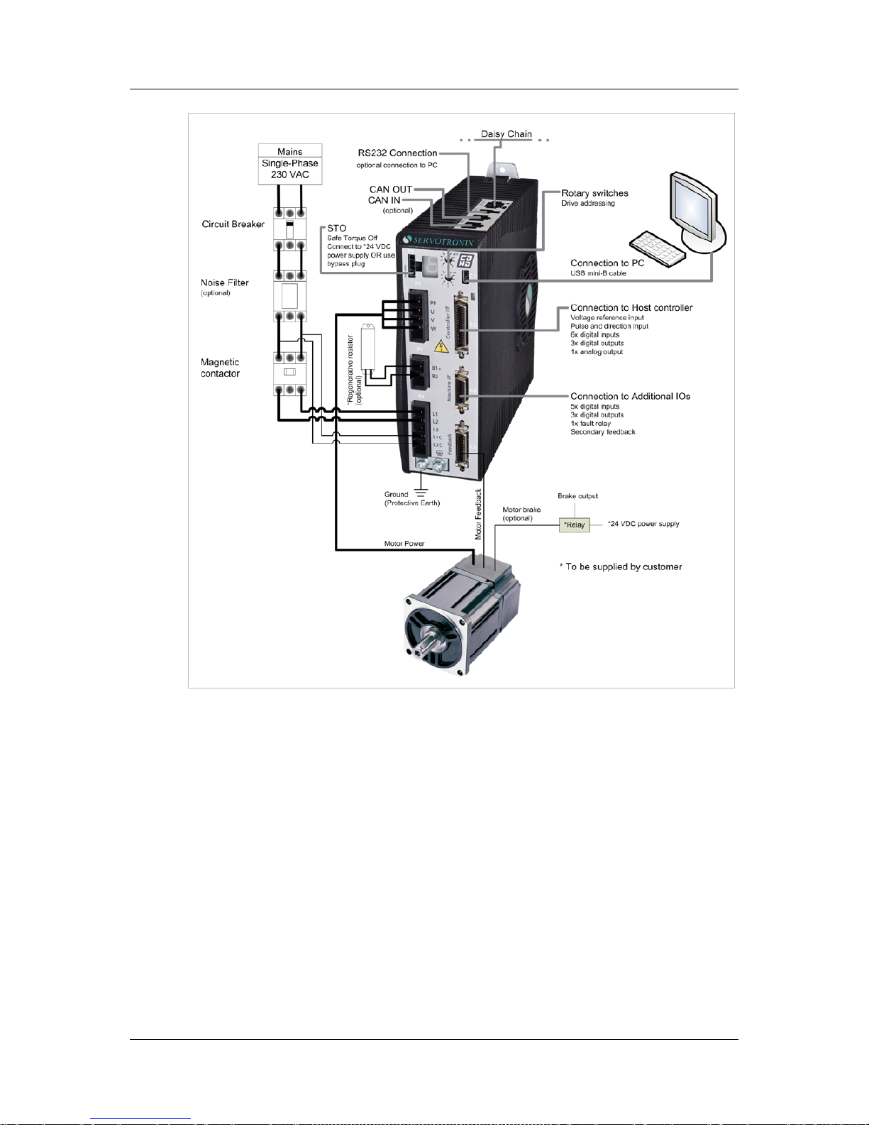
2.3 System Wiring - Pin Assignments
Figure 2-3. Pin Assignme nts
Page 21

CDHD Installation
User Manual 15
3 Installation
3.1 Installation Overview
Perfor m the follo wing ste p s to install and setup a CD HD sy s te m .
1. Mount the CDHD.
2. Connect the motor to P2.
3. Connect saf e torque off (STO) to P1, or use the pre-wired jumper connector,
which is supplied with the drive.
4. Connect regen resistor to P3, if required.
5. Connect motor feedback to C4.
6. Connect machine I/Os to C3 and/ or controller I/Os at C2.
7. Set the drive address using the rotary switches.
8. Connect the drive to the PC.
9. Connect AC inp ut voltage to P4.
10. Power up the drive and the PC.
11. Install Ser v o S tudio sof tw a r e .
12. Using ServoStudio, configu re and test the drive .
3.2 Preparation
3.2.1 Hardware Requirements
The following hardware is required for installati on.
Mating connectors and the associated crimp pins for interfaces P1, P2, P3
and P4; these are supplied with the CDHD driv e. The mating conne ctor for
P1 (STO) is supplied pre-assembled with e STO bypassed via wire jumpers.
Mating c onne ctors for inte rfaces C2, C3 an d C4 :
Connector C2 (Controll er I/O):
Plug 3M 10136-3000PE and s he ll 3M 10 33 6-52F0-008
Connector C3 (Machine I/O):
Plug 3M 1012 0-3000PE an d she ll 3M 10 320-52F0-008
Connector C4 (Motor feed b ack):
Plug 3M 1012 6-3000PE an d she ll 3M 10 326-52F0-008
Wires for gauges:
Connector P1 (STO): 26–30 AWG.
Connectors P2 (Motor Power), P3 (Regen) and P4 (AC Input):
14–16 AWG.
Connectors C2 (Controller I/O), C3 (Machine I/O) and C4 (Motor
Feedback): 24–28 AWG.
Page 22

Installation CDHD
16 Servotronix
Crimping tools, if you are not using ready-made cable assembli es:
Connector P1 (STO): Molex crimper 0638190000
Connectors P2 (Motor Power), P3 (Regen) and P4 (AC Input):
JST crimper YRF-1070. If a crimp pin extraction tool is needed, use
JST extraction tool EJ-JFA J3.
M4 ring or spade terminal.
A small slotted screwdriver for setti ng the dr ive ad dress swi tc hes.
For connection to the host computer, use one of the following :
USB 2.0 A to Mi ni-B cable (USB interface)
4p4c plug and cable (RS232 interface)
3.2.2 Computer Requirements
To inst all an d run ServoStudio software, the GUI-based configuration and testing
environment, the following computer system is required:
2 GHz CPU
1 MB RAM
1000 MB available on hard drive (after .net 4 is installed)
USB port for connecting to the drive
Operating system: Windows XP-SP3, or Win d ow s 7
.Net4 installed (for details, refer to .NET Framework System Requirements).
If .NET 4 is no t installed o n the compu te r , Se rv oStudio w ill guide yo u
through the installation, but will not install it automatically.
Page 23
CDHD Installation
User Manual 17
Figure 3-1. CDHD servo system wiring, using single-ph ase 230 VAC
Page 24

Installation CDHD
18 Servotronix
3.2.3 Electrical Requirements
Grounding
System grounding is essential for prop er p erformance of the d rive system. A
ground bus bar may be used as a single point ground for the system. Safety
groundin g should be provided to all pieces of the system from a st ar point.
In addition to the safety grounding, a high frequency ground must be provided
that connects the back panel to the enclosure and to earth ground. The objective
is to provide an extremely low impedance path between the filters, drives, power
supplies, and earth ground.
This high frequency ground is accomplished with the use of a flat braid or copper
bus bar. It is important not to rely on a standard wire for th e high frequency
ground. In general, a wire has an inductance of 8 nH per inch, regardless of
diameter. At higher frequencies, this unwanted inductance between grounds
equates to limited filter performance. When connecting high frequency grounds,
use the shortes t braid pos s ible.
Bonding
The proper bonding of shiel d ed cables is imperative for minimiz ing noise
emissions and increasing immun ity levels of the drive syste m. Its effe c t is to
reduce the impedance between the cable shield and the back panel. Servotronix
recommends that all shielded cables be bonded to the back panel.
The motor and feedback cables should have the shield exposed as close to the
drive as possible. This exposed shield is bonded to the back panel using either
non-insulated metallic cable clamps or cable bonding clamps offered by Phoenix
Contact (and others).
CE Filtering Techniques
The CDHD dri ve sy stem (bus module, d rive, motor) complies with the CE
standards specified in the section Standards Compliance. Proper bonding and
groundin g techniques must b e applied when in cor p orating EMC noise filteri ng
components in order to meet this standard.
Noise currents often occur in two types. The first is conducted emissions that are
passed through ground loops. The quality of the system grounding scheme
inversely determines the noise amplitudes in the lines. These conducted
emissions are of a common-mode nature from line to ne utral (or ground ). The
second is radiated high-frequency e m is s ions usu a lly capacitively coupled from
line-to-line and are differential in nature.
To properly mount the filters, the enclosure should have an unpainted metallic
surface. This allows for more surface area to be in contact with the filter housing
and provides a lower impedance path between this housing and the back plane.
The back panel, in turn, has a high frequency ground strap connection to the
enclosure frame or earth ground.
Page 25

CDHD Installation
User Manual 19
Input Power Filt eri ng
The CDHD electronic system components require EMI filtering in the input power
leads to me et the conducted e m is s ion requ ir e ments for the industria l
enviro n m ent. This filter ing block s c o nducted type emissions from exiting onto
the power lines and provides a barrier for EMI on the power lines.
Care must be taken to adequately size the sys te m. The type of fi lter is
determined accordin g t o the voltage and current rating of the system and
whether the inco ming line is single- or t hree-phase . O ne input line fi lter is used
for multi-axis control applications. Mount these filters as close to the incoming
power as possible to p revent noise fr om being capacitively coupled into other
signal leads and cables. Similarly, use care when routing wires fr o m t he load
side of the filter to the bus module. These lines may be noisy and must be
separated from other sensitive cabling to avoid unwanted coupling of noise.
Several suitable filters are listed in Table 3-1. Manufacturers should be able to
recommend the best filter design for particular motor control applicati ons.
Implementation of the EMI filter must ad here to the following guidelines:
Filter must be mounted on the same panel as the drive and bus module.
Filter must be mounted as close as possible to incoming cabinet power.
Filter must be mounted as close as possible to bus module. If separa tio n
exceeds 30 cm, a flat cable (braid) is used for the high frequency connection
between filter and bus module.
When mounting the filter to the panel, remove any paint or material
covering. Use an unpainted metallic back panel, if possible.
Filters are provided with a ground connection. All ground connections must
be tied to ground.
Filters can produce high leakage currents. Filters must be grounded
before connecti ng the supply !
Filters s ho u ld no t b e to uc he d fo r 10 s ec onds aft e r removing t he sup ply.
Table 3-1. Recommended EMI Li n e F i lters
Bus Module Mod el # Recommended EMI Line Filter
CDHD-003 Filter Concepts SF7
Schaffner FN258-7/07
CDHD-006 Filter Concepts SF15
Schaffner FN258-16/07
CDHD-0013 Schaffner FN258-16/07
Note:
The filte rs liste d in this tab l e are used on a one-to-one correspondence with the
drive. If drives are paralleled off one filter, it needs to be sized. Drives can be
ganged off one EMI filter.
Page 26

Installation CDHD
20 Servotronix
Motor Line Filtering
Motor filtering may not be necessary for CE compliance of CDHD systems.
However, this additional filtering increases the reliability of the syst em. Poo r
non-metallic enclosure surfaces and lengthy, unbonded (or unshielded) motor
cables that couple noise line-to-line (differen tial) are just some of the factors
that lead to the necessity of motor lead filtering.
Motor lead noise may be either common-mode or differential . The commonmode conducted currents occur between each motor lead and ground (line-toground). Differential radiated currents exist from one motor lead to another
(line-to-line). The filterin g of the lines feeding the motor provides additional
atten ua t io n o f noise curr ents that enter s urrounding cables and eq u ip ment I/O
ports in close proximity.
3.3 Mechanical Installation
3.3.1 Mount the CDHD
Using the bracket on the back of the CDHD, mount the CDHD on a grounded
conductive metal panel.
For mounting di mensions, refer to Figure 2-1.
3.4 Electrical Installation
3.4.1 Connect Motor (P2)
Using the supplied mating connector, connect the motor interface.
Figure 3-2. Motor Interface
Table 3-2. Motor Interface
Pin Pin Label Function
1 PE Protective ground (motor housing)
2 U Motor Phase U
3 V Motor Ph a se V
4 W Motor Phase W
Page 27

CDHD Installation
User Manual 21
Table 3-3. Motor Interface Mati ng Connector
Item Specification
Manufacturer JST
Housing and
4-pin crimp
Part # F32FSS04-V-KX an d
Part # SF3F71-GF-P0.2
Spring terminal Par t # 04JFAT-SAYGF-I
Wire Gauge 14–16 AWG
3.4.2 Connect STO (P1)
Safe torque off (STO) is a safety function that prevents the drive from delivering
power to the motor, which can generate torque.
STO Enable and STO Return must be connected to enable CDHD operation. The
STO Enab le signa l v o ltage mus t b e 24 V D C .
Using the supplied mating connector, connect the STO interface.
If the application does not require STO functionality, connect pin 4 to pin 1, and
pin 3 to pin 2.
Figure 3-3. STO Interface
Table 3-4. STO Interface
Pin Pin Label Function
1 24V STO Enable
2 GND STO Return
3 24V Return
4 24V Su pply
Table 3-5. STO Interface Mating Connector
Item Specification
Manufacturer Molex
Housing and
4-pin crimp
Part # 436450400 and
Part # 436450400
Wire Gauge 26–30 AWG
Page 28
Installation CDHD
22 Servotronix
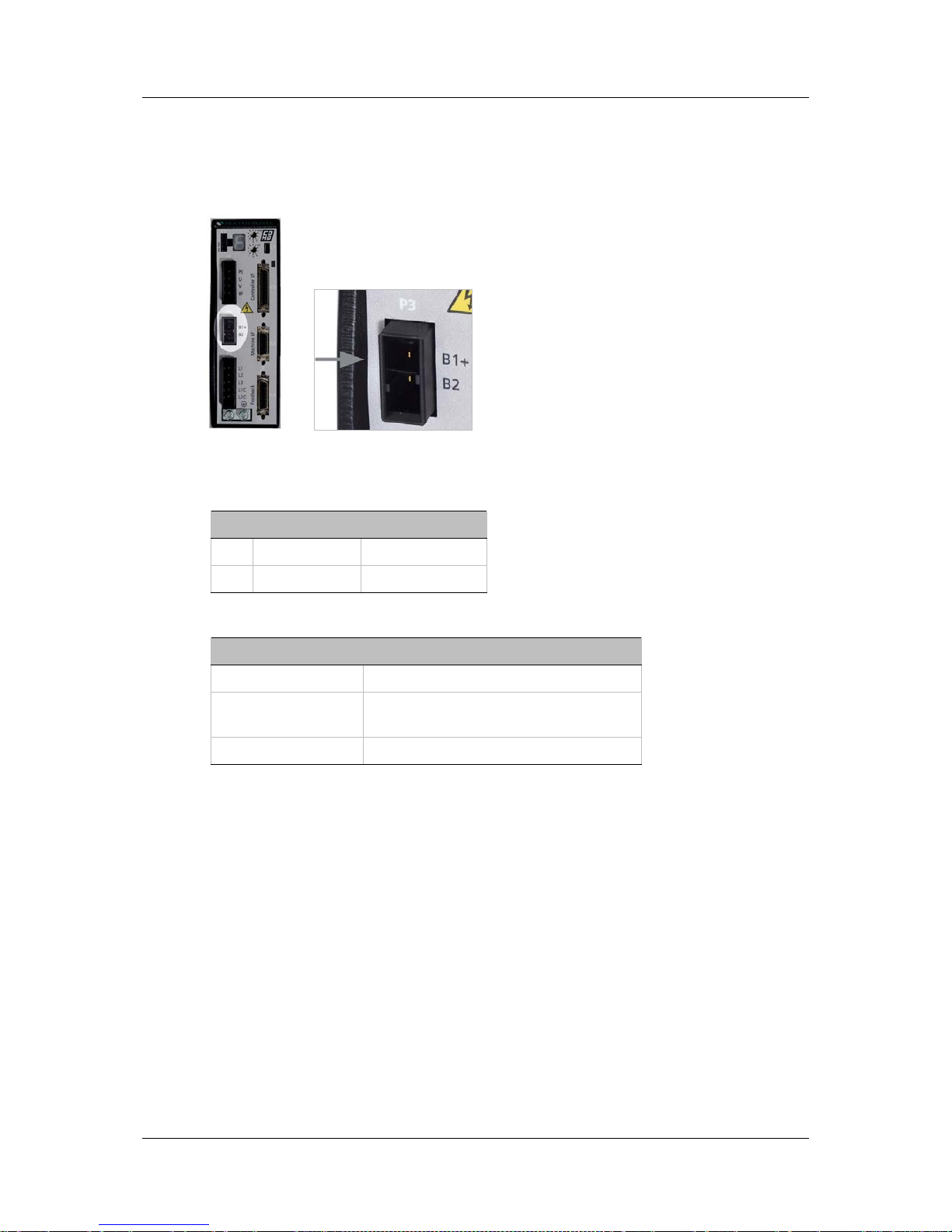
3.4.3 Connect Regen (P3)
If the application requires a regeneration (regen) resistor, use the P3 interface.
Using the supplied connector, connect the regen resistor between terminals B1+
and B2.
Figure 3-4. Regen Interface
Table 3-6. Regen Interface
Pin Pin Label Function
1 B1+ DC bus +
2 B2 Regen bus -
Table 3-7. Regen Interface Mating Connector
Item Specification
Manufacturer JST
Housing and
2-pin crimp
Part # F32FSS02-V-KX and
Part # SF3F71-GF-P0.2
Wire Gauge 14–16 AWG
3.4.4 Connect Motor Feedback (C4)
Wire the motor feedback interface according to the type of feedback device to be
used in your application. Refer to the guidelines following the pinout table below.
Pins 1, 2, 14 and 15 have dual functionality.
Pins 11 and 13 for 5V to the encoder are used in digital board revision 0. Pin 18
can be used only in digital board revision 1 and later.
Pin 25 for the motor temperature sensor is connected internally in the drive to
CDHD ground.
Unused pins must remain unwired.
Page 29

CDHD Installation
User Manual 23
Figure 3-5. Motor Feedback Interface
Table 3-8. Motor Feedback Interface
Pin Function Pin Function
1 Incremental encoder A +
or SSI encoder data +
14 Incremental encoder A -
or SSI encoder data -
2 Incremental encoder B +
or SI encoder clock +
15 Incremental encoder B -
or SSI encoder clock 3 Incremental Encoder Z + 16 Incremental encoder Z 4 Hall U + 17 Hall V+
5 Hal l W + 18 5V supply
6 Resolver sine + 19 Resolver sine 7 Resolver cosine + 20 Resolver cosine 8 Resol ver reference + 21 Reso lver refe renc e 9 Sine encoder sine + 22 Sine encoder sin e 10 Sine encoder cosine + 23 Sine encoder cosine 11 5V supply 24 Ground
12 Motor temper at ure sensor 25 Motor temperatur e se nsor
13 5V supply 26 Shield
Wiring Guidelines
For incr emen tal encoder with Halls, use pins 1, 14, 2, 15, 3, 16, 4, 17, 5,
18, 24
For resolver, use pins 6, 19, 7, 20, 8, 21
For sine encoder, use pins 9, 22, 10, 23, 11, 24
For sine encod er with Hal ls, use pi ns 9, 22, 10, 23, 11, 24, 4, 17, 5, 18
For EnDat 2.1 encoder, use pins 1, 14, 2, 15, 9, 22, 10, 23, 11, 24
Page 30
Installation CDHD
24 Servotronix
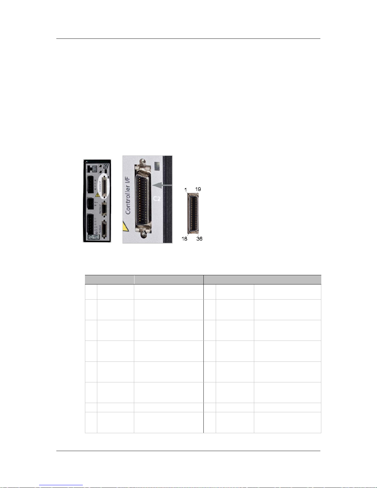
3.4.5 Connect Controller I/Os (C2)
Wire the digital and analog inputs and outputs according to the requirement s of
your appl ication.
Wire the digital and analog inputs and outputs according to the requirement s of
your appl ication.
Unused pins must remain unwired.
To preserve isolation of the digital I/Os, connect a 24 VDC source to pin 19.
Connec t t he re t urn of the 24 VDC supply to pin 1, which functions as the ground
path for the outputs.
Note: The 24 VDC supp ly and return can be connected on either th e Controller
interface (C2) or the Machine interface (C3), but it is not necessary to
connect it on both.
Figure 3-6. Control l er I/O Interface
Table 3-9. Controller I/O Interface
Pin Function Description Pin Function Description
1 24 VDC return
Return of the user-supplied
24 VDC
19 24 VDC
User supplied 24V, f or I/O
biasing
2
Digital
output 1
Opto-isolated
programmable dig it al
output. Read using OUT1
20 Digital input 2
Opto-isolated
programmable dig it al
input. Read using IN2
3 Digital input 1
Opto-isolated
programmable dig it al in p ut .
Read using IN1
21 Reserved for future use
4
Equivalent
encoder
output A-
Low side of the equivalent
encoder output signal A
(RS422)
22
Equivalent
encoder
output A+
High side of the e quivalent
encoder output signal A
(RS422)
5
Channel Bout
Low side of the equivalent
encoder output signal B
(RS422)
23
Channel B+
out
High side of the e quivalent
encoder output sig na l B
(RS422)
6
Channel Zout
Low side of the equivalent
encoder output index
(RS422)
24
Channel Z+
out
High side of the e quivalent
encoder output index
(RS422)
7 5V 5 VDC source 25 Ground Digit al ground
8
Analog
input 1+
High side of the differential
analog command input
(±10 VDC)
26
Analog
input 1-
Low side of the diff e re nti al
analog command input
(±10 VDC)
Page 31

CDHD Installation
User Manual 25
Pin Function Description Pin Function Description
9
Direction
input+
High side of the direction
signal (RS422)
27
Direction
input-
Low side of the direction
signal (RS422)
10 Ground Digital ground 28 Pulse input+
High side of the pulse
signal (RS422)
11 Pulse input-
Low side of the pulse sig na l
(RS422)
29 Ground Dig ita l g roun d
12 Reserved for future use 30 Reserved for future use
13 Ground Digital ground 31 Digital input 3
Opto-isolated
programmable dig it al
input. Read using IN3
14 Digital input 4
Opto-isolated
programmable dig it al in p ut .
Read using IN4
32 Digital input 5
Fast opto-isolated
programmable dig it al
input. Read using IN5
15 Digital input 6
Fast opto-isolated
programmable dig i tal in p u t.
Read using IN6
33
Digital
output 2
Opto-isolated
programmable dig it al
output. Read using OUT2
16
Digital
output 3
Fast opto-isolated
programmable dig it al
output. Read using OUT3
34 Reserved for future use
17 Reserved for future use 35*
Analog
input 2-
Low side of the second
differential a na log input
(±10 VDC)
18*
Analog
input 2+
High side o f t he second
differential a na log input
(±10 VDC)
36 Analog output
Analog output, referenced
to digital ground (0 -10
VDC)
* Optional, see ordering information
3.4.6 Connect Machine I/Os (C3)
Wire the machine inputs and outputs according to the requirements of your
application.
Unused pins must remain unwired.
To preserve isolation of the digital I/Os, connect a 24 VDC source to pin 9.
Connec t t he re t urn of the 24 VDC supply to pin 19, which functions as the
ground path for the outputs.
Note: The 24 VDC supply and return can be connected on either the Controller
interface (C2) or the Machine interface (C3), but it is not necessary to
connect it to both.
Figure 3-7. Machine I/O Interface
Page 32

Installation CDHD
26 Servotronix
Table 3-10. Machine I/O Interface – 20-pin MDR Plug
Pin Function Description Pin Function Description
1
Secondary
encoder A+
High side o f t he secondary
encoder input signa l A
(RS422)
11
Secondary
encoder A-
Low side of the secondary
encoder input signa l A
(RS422)
2
Secondary
encoder B+
High side of the secondary
encoder input signa l B
(RS422)
12
Secondary
encoder B-
Low side of the secondary
encoder input signal B
(RS422)
3
Secondary
encoder Z+
High side o f t he secondary
encoder input index
(RS422)
13
Secondary
encoder Z-
Low side of the secondary
encoder input index
(RS422)
4
Secondary
encoder 5V
5 VDC supply for the
secondary e n coder
14
Secondary
encoder
ground
Ground of the 5 VDC supply
for the secondary encoder.
5
Digital
input 7
Opto-isolated
programmable dig it al in p ut .
Read using IN7
15 Digital input 8
Opto-isolated
programmable dig it al in p ut .
Read using IN8
6
Digital
input 9
Opto-isolated
programmable digital input.
Read using IN9
16
Digital
input 10
Opto-isolated
programmable dig it al in p ut .
Read using IN10
7
Digital
input 11
Fast opto-isolated
programmable dig it al in p ut .
Read using IN11
17
Digital
output 4
Opto-isolated
programmable dig it al
output. Read using OUT4
8
Digital
output 5
Opto-isolated
programmable dig it al
output. Read using OUT5
18
Digital
output 6
Fast opto-isolated
programmable dig it al
output. Read using OUT6
9 24 V DC
User supplied 24V, f or I/O
biasing
19 24 VDC return
Return of the user-supplied
24 VDC
10 Fault relay 1
Terminal 1 of the dry
contact fault relay
20 Fault relay 2
Terminal 2 of the dry
contact fault relay
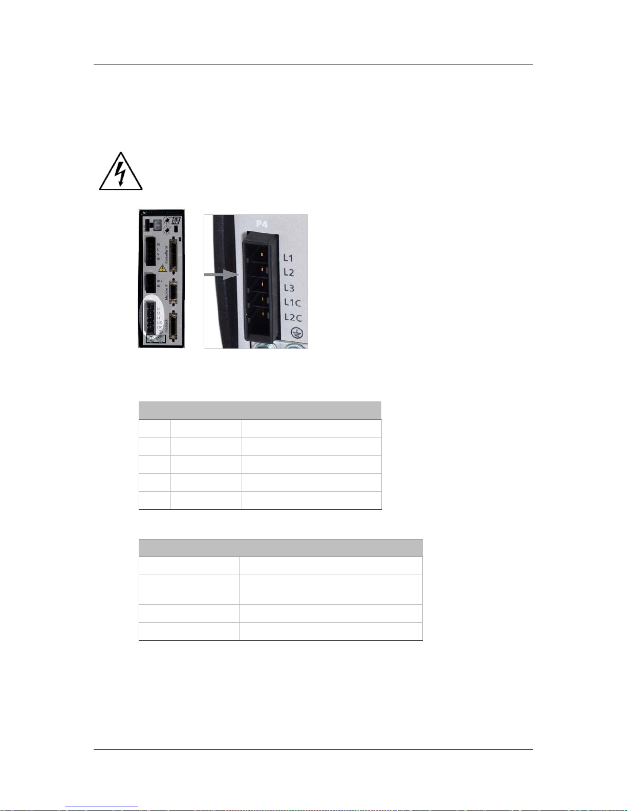
3.4.7 Connect AC Input Voltage (P4)
The AC voltage interface supplies both motor (bus) power and logic power.
Using the sup plied ma ting con nector, ma k e t he following connec tions:
1. Connect L1, L2 and L3 (for bus power).
If the main voltage is from a singl e-phase so ur c e , connect line a nd
neutral to L1 and L2.
If the main voltage is from a thre e-phase source, connect the phases to
L1, L2 and L3.
2. Connect the AC input vol ta g e g r o u nd w ir e to the PE terminal, locate d on the
CDHD front panel. Use an M4 ring or spade terminal.
Figure 3-8. Ground Terminals
Page 33
CDHD Installation
User Manual 27
3. Connect L1C and L2C (for logic powe r).
If the main voltage is from a singl e-phase so ur c e , connect line a nd
neutral to L1C and L2C.
If the main voltage is from a thre e-phase source, connect any two
phases to L1C and L2C.
Make sure the m a i n voltage rating matches the drive specifi cat i on.
Applying incorrect voltage may cause drive failure.
Do not apply p ow er until all ha rd w a re connections are compl ete.
Figure 3-9. AC Input Voltage Interface
Table 3-11. AC Input Voltage Int erface
Pin Pin Label Function
1 L1 AC Phase 1
2 L2 AC Phase 2
3 L3 AC Phase 3
4 L1C Logic AC Phase 1
5 LC2 Logic AC Neutral
Table 3-12. AC Input Voltage Int erface Mating Connector
Item Specification
Manufacturer JST
Housing and
5-pin crimp
Part # F32FSS05-V-KX and
Part # SF3F71-GF-P0.2
Spring terminal Part # 05JFAT-SAYGF-I
Wire Gaug e 14–16 AWG
3.5 Set the Drive Address
The CDHD has two 10-pole rotary switches, accessible from the front of the unit.
The switches are used to set the drive address. When there is more than one
drive on a daisy-chain or CANbus network, each drive must ha v e a u nique
address to enable its identification on the network.
Page 34

Installation CDHD
28 Servotronix
Use the two rotary switches to set the drive address for both CAN and serial
communication.
For Ethernet -based motion buses, the switch has no functional use for either the
drive or t he network. It can be used at the application level to identify specific
drives on a network.
Each switch has 10 positions:
The upper switch positions are set as tens: 10, 20, 30 … 90
The lower switch positions are set as ones: 0, 1, 2 … 9
Note: If two or more drives are connected to the network, address 0 cannot be
used. A singular drive may have the address 0.
Figure 3-10. Drive Address R ot ary Sw i tches
3.6 Connect to PC (C1 or C7)
To connect the d rive to the host computer, use either one of the following
interfaces:
USB port (C1). Use a USB 2.0 A to Mini-B cable.
Figure 3-11. USB Port
Page 35

CDHD Installation
User Manual 29
RS232 port (C7). Use a 4p4c plug.
Figure 3-12. RS232 Port
Table 3-13. RS232 Interface
Pin Pin Label Function
1 RX Receive
2 GND ISO Ground
3 TX Transmit
4 Unused
3.7 Power Up
1. After completing the hardware connections, turn on power to the drive.
2. Look at the 7-segment display on the CDHD front panel.
Upon initial power up, the status display should flash -1 (alternating “-” and
“1”), indicating that the drive is operational, but not yet configured.
Figure 3-13. LED Status Display
The digital display provides various indications of drive operation, such as
operation modes, drive enable status, and fault conditions.
For more information, refer to the section Oper ation Mode Codes.
3.8 ServoStudio Software Installation
Use ServoStudio software to configure the drive for your application.
1. Install ServoStudio on the host computer.
2. When installation is complete, start ServoStudio from the Windows Start
menu or the shortcut on your desktop.
Page 36

Configuration an d Operation CDHD
30 Servotronix
4 Configuration and Operation
4.1 Variables and Commands
Drive functionality is configured using various commands and variables, which
are transmitted over the communication bus. The terms “variables” and
“parameters” are used interchangeably; “dr ive p aramet er set” refe rs to the set
of variables that are specifically defined for a particular application.
Commands and variables are identified by a mnemonic (VarCom) name. For
example, MPOLES is the mnemonic used to read and write the settin g for the
number of m otor poles.
VarCom instructions, which are used with serial communications, are detailed in
the CDHD VarCom Reference Manual.
Some variables are read-only, while others allow read/write access. Variables
can be stored in the CDHD’s no n-volatile memory (flash memory) for use at each
power-up.
In gener a l, d rives are shipped fr o m the facto ry with m o to r par amete rs set to
zero and application parameters set to their default values.
4.2 ServoStudio Software
ServoSt ud io is a graphic interface provided with the CDHD to enable setup,
configuration and tuning of the drive.
ServoStu d io allows you t o prog ram the drive parameters speci fically for the
motor to which the CDHD is connected, and for the particular operation that the
drive wil l b e performing in the machine.
ServoStudio provides two primary ways for setting up the CDHD servo drive.
Using the Setup Wizard, which takes you step-by-step through the setup
and configuration process; this method is recommended for novice users.
Using each setup windo w ind iv idua l ly, to acc ess a nd de fine sp ec if ic driv e
functions.
The ServoStudio window has four function areas:
Toolbar
Contains quick access buttons for CONFIG ( to trigger inte rnal
drive configuration), Enable/Disable, Offline/Onli ne a nd Sa ve
(to save parameters to non-volatile memory).
Page 37
CDHD Configuration and Operation
User Manual 31
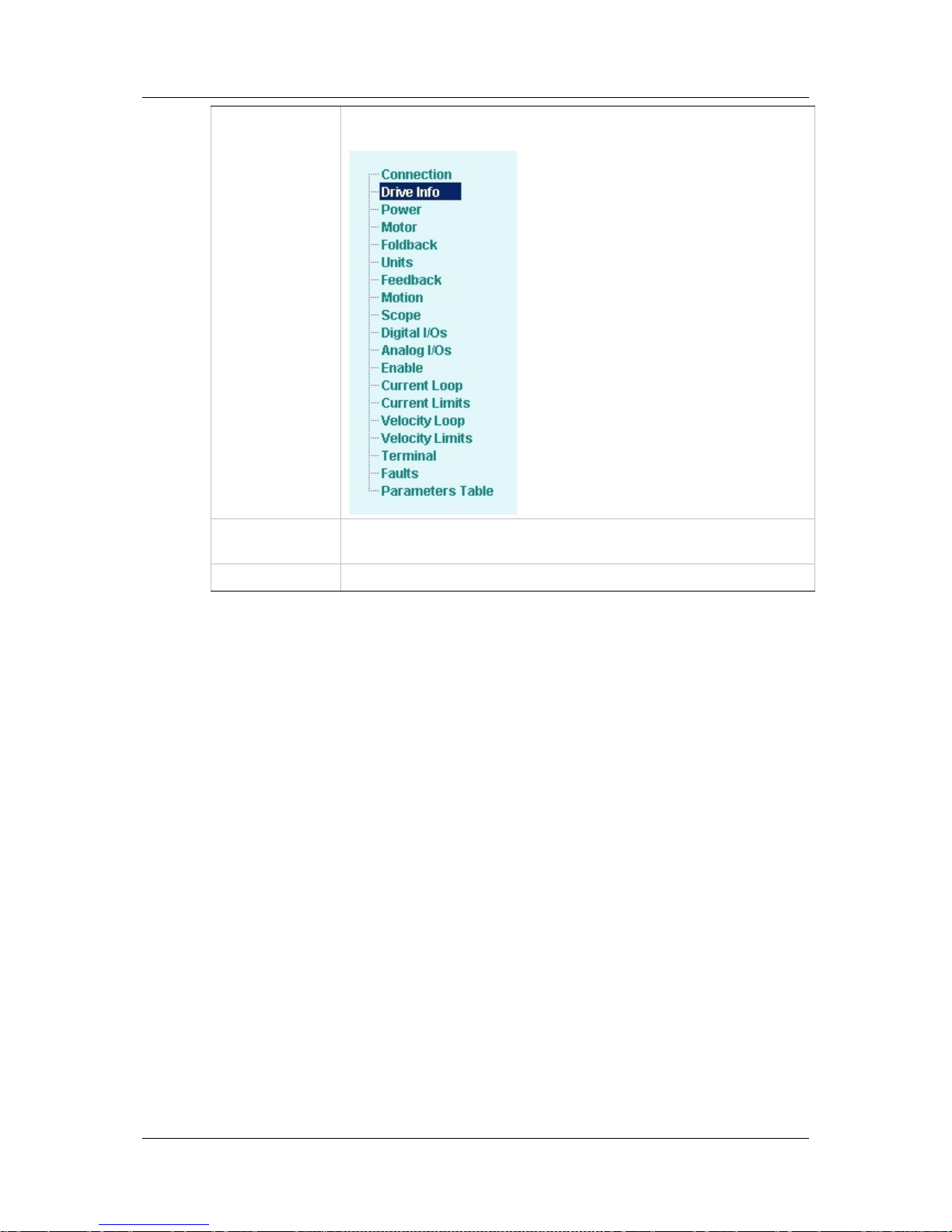
Sidebar
Contains a navigation menu for the drive functions. The
sidebar can be viewed or hidden using the Arrow icon.
Main Screen
Displays various interactive screens for viewing, setting and
testing parameters and drive configurations.
Status Bar Displays messages and warnings.
4.3 Connecting to a Drive
In the ServoStudio sidebar, click Connection.
The main screen now shows the various connection options.
Make the selections that match your setup.
4.4 Enabling/Disabling a Drive
4.4.1 Drive Enable
The drive is enabled when three conditions exis t, as shown in Figure 4-1.
No Faults
The drive can be enabled only when no faults exist.
Software Enable
The commands EN and DIS set the Software Enable state of the drive.
For the C DHD analog versi on, Software Enable is on at power up, which
allows the drive’s enable state to be controlled by the Remote Enable
signal.
For the CDHD CAN and other motion-bus versions, Softwa re Enab le is
off at power up, and the drive is enabled by means of specific control
words.
Page 38

Configuration an d Operation CDHD
32 Servotronix
Remote (Hardware) Enable
This is a s ig nal in the ra nge of 5—24 VDC that is applied to one of the optoisolate d d igital inputs in the Controller I/O connector.
The input m u st be configured fo r use a s the Remote (Hardware) Enable
input, using INMODE.
The state of the signal can be read, using REMOTE.
Figure 4-1. Drive Enab le Conditi ons (ServoStudio d iagram)
4.4.2 Operation Mode Codes
Once the drive is ready for operatio n, the 7-segment display shows a steadily-lit
single digit, indica ting the operation mode currently in effect.
Table 4-1. Operation Mode on 7-Segment Display
Display Name Description
. Drive enabled
0 OPMODE 0 Serial velocity co ntrol
1 OPMODE 1 An al og velocity control
2 OPMODE 2 Serial current control
3 OPMODE 3 Analog current control
4 OPMODE 4 Master/slave gearing control
8 OPMODE 8 Position control
For more information, refer to the section Drive Statu s 7 -Segment Display.
Caution: Enabling the drive might cause the motor to move.
Page 39

CDHD Configuration and Operation
User Manual 33
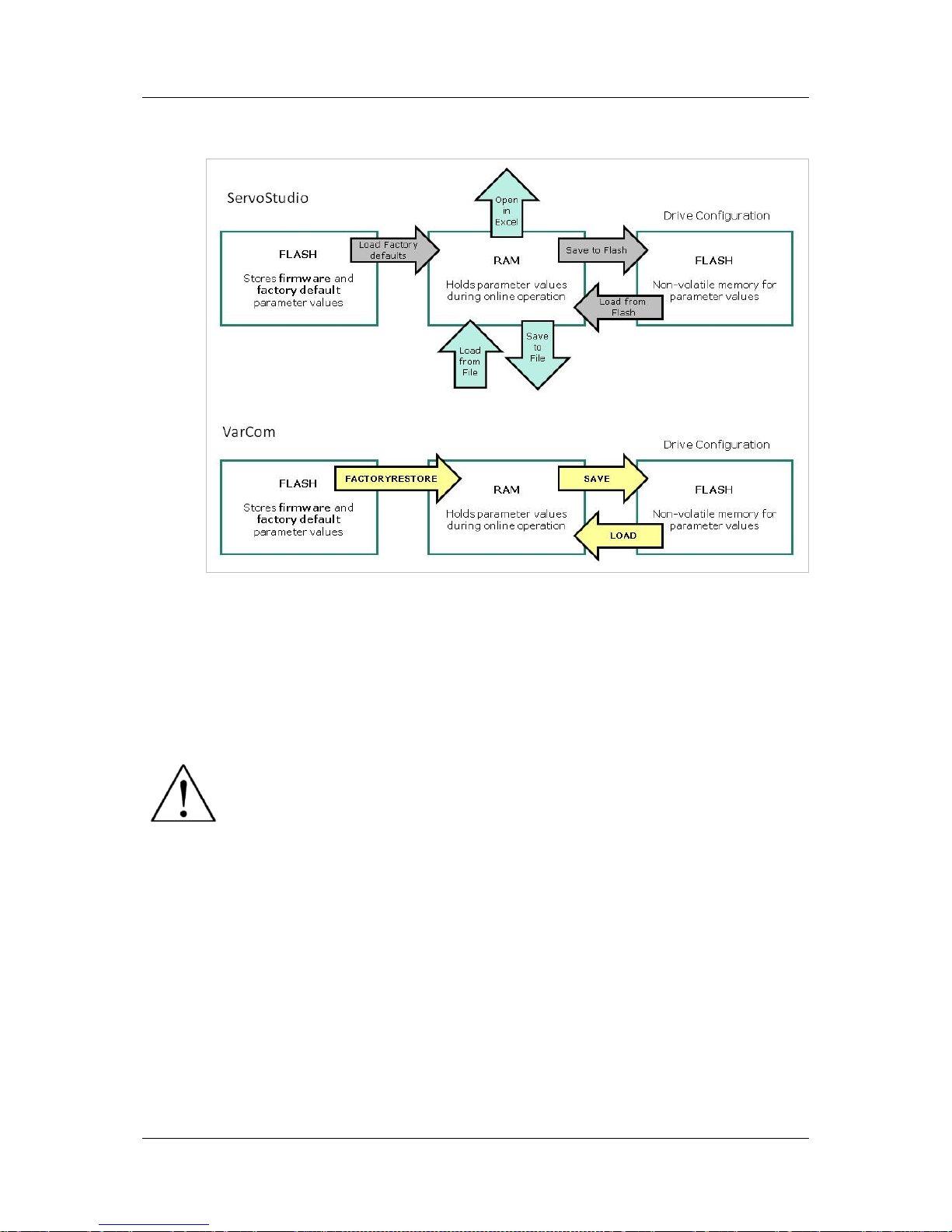
4.5 Managing Drive Parameters
The CDHD dri ve has two types of memor y f or storing the drive’s parameters:
Flash: Non-volatile memory. It holds the drive’s default parameter values
(contained within the drive’s firmware), as well as the saved set of
parameters. After you have tested and confirmed that the drive is
performing as i ntended, save the parameters to the flash memory. You
should also save them to a file as a backup.
RAM: Volatile memory. The drive’s working memory. Parameter values are
maintained in RAM while you configure and test the drive and adjust
parameters. If power to the drive is disconnected, any unsaved changes in
the parameters will be lost.
During p ow er up, the CDHD loads p a rameter values from the flash memor y to
the RAM, and a checksum of these parameter values is calculated. If the
checksum is invalid, default parameter values (which are hard-coded in the
drive’s firmware) are loaded into RAM and a Parameter Memory Checksum
Failure fault is se t.
Drive parameters may be saved to non-volatile memory at any time by clicking
on the Save icon in the ServoStudio toolbar.
The Parameters Table in Ser voStudio includes additional options for loading and
saving the drive’s parameters.
Load from Driv e
Loads into RAM the parameter values last saved in the
non-volatile memory. Use this option to revert to the
previous saved con figuration.
Write to Drive
Saves the parameters currently in RAM to the non-volatile
memory.
Load from PC Loads into RAM paramete r from a file on your PC.
Write to PC Saves parameters from RA M to a file on your PC.
Page 40
Configuration an d Operation CDHD
34 Servotronix
The following diagram il lustrates the relationships among the different types of
memory in the CDHD drive.
Figure 4-2. Drive Mem ory Archite ctu re
For more inf ormation on the comma nds for saving and loa d ing parameters, refer
to the CDHD VarCo m Reference Manual.
4.6 Configuring Parameters Using ServoStudio
Disable the dri v e before mani p u l a ting motor and feedback
parameters.
Many parameters can be modified while the drive is enabled.
Exercise caution, however, as motor behavior will change.
If a parameter cannot be modified while the drive is enabled, ServoStudio
will prom pt you to d is a ble the dr iv e.
While setting the paramet e rs, pay close att en tion to any warn ing or error
messages displayed by ServoStudio.
4.6.1 Tuning and Testing
In the Motion screen, various types of motion can be executed. In this screen
the values of actual current, velocity and position are displayed. This is not realtime data, however, and the update rate depends on such factors as the host
computer processing pow er and the drive mode of ope ration.
Drive tuning is generally performed in the Scope screen. This screen allows t he
you to record drive parameters, and to configure the record trigger to match the
specific motion being recorded.
Page 41

CDHD Configuration and Operation
User Manual 35
4.6.2 Drive Info
The Drive Info screen displays basic information about the CDHD, such as
current rating , ha rd w a re vers ion and fir m w a re versio n. It is important to
provide this information to Servotr onix Technical Su pport when asking for
assistance. Th is scre en also provi des access to the Firmware Download utility.
4.6.3 Power
The Power screen displays the drive’s continuous and peak current ratings, and
allows you to set the bus voltage parameters. These parameters include:
The nominal bus voltage that will be applied to the drive: 320 V for a drive
powered by 220 VAC per phase, and 160 V for a drive powered by 110 VAC
per phase.
Under-voltage mode. Defines how the drive will respond to an under-voltage
fault.
Under-voltage time. Specifies the amount of time an under-voltage
condition will exist before latching a fault, when working in Delayed Fault
Under-Voltage mode.
Under-voltage recovery. Defines how the dri ve will recover fr om an under-
voltag e f au lt: recovers automatically or by toggling dr ive from disab le to
enable.
Refer to VBUS, UVMODE, UVTIME and UVRECOV ER in the VarCom Reference
Manual.
4.6.4 Motor
The Motor screen allows you to select a motor from the ServoStudio database.
You can simply select the motor family and motor part number, and ServoStudio
will prepare the appropriate motor and feedback parameters. Select Write to
Drive to send the parameters to the drive.
The screen also allows you to read parameters from the drive, and save
parameters.
4.6.5 Foldback
The Foldback screen allows you to set the foldback properties of the drive and
motor, and to activate the motor foldback feat ure.
4.6.6 Units
The Units screen lets you select the position, velocity and acceleration/
deceleration units that you prefer for working with a rot ary motor.
Refer to UNITSROTPOS, UNITSPOSVEL and UNITSPOSACC in the VarCom
Reference Manual.
4.6.7 Feedback
The Feedback scree n e na bles you to configur e the properties of the motor’s
feedback device, and to view the feedback according to your preferences.
To configure feedback, select the feedback device from the Feedback options.
The screen will change accordingly, enabling you to set the relevant feedback
properties.
Page 42

Configuration an d Operation CDHD
36 Servotronix
The Feedback screen also allows you to activate the encoder simulation output
and set its resolution .
4.6.8 Motion
The Motion screen allows you to choose the operation mode and to set the
relevant motion settings. It also all ows you to execute motion and to view the
actual current, velocity and position of the motor.
4.6.9 Scope
The Scope screen enables you to configure recording settings, record data from
the drive, and display the data according to your preferences. It also enables
you to conduct motion if required and send commands to the drive via terminal.
4.6.10 Digital I/Os
The Digital I/Os screen enables you to configure functionality and polarity of
the digital I/Os, and to monitor the state of all digit a l I/Os.
4.6.11 Analog I/O
This Analog I/Os screen lets you set various properties of the analog inputs,
such as functionality, manual or automatic offset level, low pass filter, and dead
band range. It also allows you to m onitor the state of all analog in p uts.
4.6.12 Enable
The Enable screen displays the state of all conditions required for the drive to be
enabled.
4.6.13 Current Loop
The current loop gains are set automatically according to the motor properties
and the bus voltage. The Cu rrent Loop screen enables you to change defau lt
gains by multiplying them by a factor.
4.6.14 Current Limits
The Current Limits screen contains a diagram that shows how the ma xi mu m
current for the system is determined, and enables you to set the current limit for
your system accord i ngl y.
4.6.15 Velocity Loop
The Velocity Loop scre en ena bles you to select the type of velocity controller
you want to use, and to set the required parameters. All types of controllers are
graphically illustrated with the required parameters embedded in the schematics.
4.6.16 Velocity Limits
The Velocity Limits screen contains a diagram that shows how the max imu m
velocity for the system is determined, and enables you to set the velocity limit
for your system accordingly.
4.6.17 Terminal
The Terminal screen allows you to send ASCI I co mmands to the drive, and to
monitor p ara meters in a Watch pane.
Page 43

CDHD Configuration and Operation
User Manual 37
4.6.18 Faults
The Faults screen shows a list of drive faults. This information allows you to
identify problems and take measures to correct them.
4.6.19 Parameters Table
The Parameters Table displays and allows you to modify the drive parameters.
The pa rameters ar e grouped according to function. For each parameter you can
find a description, units, maximum value, minimum value, and cu r rent value .
In this screen you can also download parameters from the drive, upload
parameters to the dr ive , load parameters from a file, and save parameters to a
file.
4.7 ServoStudio Expert View
The Expert View screen lets you perf o rm the fo llowing ta sks:
Send ter m inal commands to the drive
Change operation mode and in itiate motion accordingly
Monitor parameters using a watch pane
Set recording properties
Set chart display properties
Run scripts
Page 44

Firmware Upgrade CDHD
38 Servotronix
5 Firmware Upgrade
The CDHD firmware can be upgr a ded using t he Se rv oStudio softwar e.
5.1 Preparation
Important: Before upgrading the firmware, backup the drive parameters since
parameter settings may be lost during the upgrade. After the upgrade is
completed, the parameters can be reloaded/restored.
5.2 Upgrade Procedure
From the ServoS tudio Drive Info screen, activate the upgrade procedure, and
follow the prompts.
Page 45

CDHD Troubleshooting
User Manual 39
6 Troubleshooting
6.1 Dr ive Status 7-Segment Display
The 7-segment display provides various indications of drive status, such as
operation modes, drive enable status, and fault conditions.
The disp la y uses the fo llowing co n v entions:
Decimal point – indicates the drive’s Enable/Disable status; if displayed, the
drive is enabled.
Steadily lit digit – indicates the specific operation mode (OPMODE) currently
in effect.
Steadily lit letter – indicates a war ning
Flashing sequence of letters and digits – indicates a fault
Flashing letter or digit – a special case (such as encoder initialization, motor
setup).
In the event of concurrent faults, only one fault code is displayed on the
7-segment displa y. The display shows the code of the fault with the highest
priority.
Refer to Table 6-1 for a complete list of fault codes, names and descriptions.
6.2 Faults and Warnings
If the CDHD is connected to a host computer via the USB o r RS232 ports, it
communicates fault codes to the computer by means of a text message. This
message is saved in a fault history log (FLTHIST) in the drive’s non-volatile
memory, so tha t th e fa ult history is not lost when po w e r is re m o v ed f ro m th e
drive.
Warnings are not considered faults and do not disable operation. The
system automatically clears the warning state when the condition that
generated the warning no longer exists.
Faults automatically disable the drive and a fault status is indicated on the
drive’s display. The drive fault status is generally latched, and the drive
cannot be enabled until the fault status is explicitly cleared. Only if the fault
condition no longer exists can the fault status be cleared. It is done by
either of the following:
Toggling the drive enable. This is done either by executing a drive
disable command (K) followed by the enabled (EN) command or by
toggling the Remote Enable line (REMOTE).
In some systems, a specific drive inpu t is define d as Alarm C lear. In this
case, toggling this input will clear the fault.
If the fault condition no longer exists, the drive is re-enabled.
Some faults are referred to as Fatal faults since they dis a ble almost all
drive functions (including communications) and prevent the drive from being
enabled. This condition is typical of faults due to internal failures, such as a
Page 46

Troubleshooting CDHD
40 Servotronix
watchdog event or a failure of an internal power source. Fatal faults requir e
intervention by technical support.
6.3 Status Information in ServoStudio
Drive status information can be found in various ServoStudio screens.
The Drive Info screen shows basic information about the CDHD, such the
current rating , ha rd w a re vers ion and fir mware v e rs ion. It is im p o r tant to
comm un icate this infor ma t ion to Servotronix Technical Su p p ort when
requesting assistance. This screen also provides access to the firmware
upgrade utility.
The Faults scree n shows a lis t of drive fa ults. Us e this infor matio n to
identify the problem and take steps to correct it.
The Digital I/O screen allows you to check the status and configuration of
the digital inputs and outputs.
The Motion screen allows you to issue motion commands in the operation
mode of your choice, and to view actual values of current, velocity and
position.
The Scope screen enables you to record data from the drive, with or
without assoc iated mo t io n.
6.4 Fault and Statu s Queries
The following commands can be used to query the status of the drive.
FLT
Returns a list of faults latched by the drive. Faults remain latched
until cleared by CLEARFAULTS or EN, provided that the fault
condition has been remove d .
FLTHIST
Returns a list of faults that have occurred since the fault buffer was
last cleared.
FLTCLR Clear s the fault histor y b u f fe r.
ST The ST command returns a textual summary of the drive status.
Refer to the VarCom Reference Ma nual for a complete list and details of variables
and commands.
6.5 Fault Codes and Names
The following table will help you interp ret fault codes and names, and respond
appropriately.
Display is the code that appears on the 7-segment display.
If the fault code is a single character (such as u), the character flashes on
and off. (The exception is F, which remains lit stead ily).
If the fault code is m o re than one cha racter (s uc h as A4), t he characte rs are
displayed one at a time, in sequence.
Fault Name is the text mess a g e d isplayed in Serv o Studio when the fault occurs.
Faults can also be viewed in t he ServoStudio Faults screen.
Page 47

CDHD Troubleshooting
User Manual 41
Table 6-1. Faults
Display Fault Name Description Action Required
≡
Watchdog Fault
Generally occurs due to a n
unforeseen circumstance. The drive
is inoperable until p owe r is cy cle d .
Contact technical suppor t.
-1 Not Configured Drive configuration required.
Set drive parameters and execute
CONFIG.
A4 CAN Supply Fault
A problem with the in te rna l v olt ag e
supply for the CANbus.
The drive probably needs repair.
Contact technical suppor t.
b Drive Locked
Security code and key do not match.
Fatal fault; drive can not b e
operated.
Contact technical suppor t.
e
Parameter Memory
Checksum Failure
The non-volatile memory use d to
store drive parame te rs is emp t y or
the data is corrupted .
Reconfigure the d rive, or download the
parameter set, and save the
parameters.
E
Failure Writing to
Flash Memory
An internal proble m acce ssing the
flash memory. Fatal fa ult; d riv e
cannot be operated.
Contact technical suppor t.
e101 FPGA Config Fail
The code for the FPGA did not load.
Fatal fault; drive can not b e
operated.
Contact technical suppor t.
e105 Self Test Fail
The power-up self test failed. Fatal
fault; drive cannot b e op e ra te d .
Contact technical suppor t.
e106
Digital EEPROM
Fault
A problem accessing the EEPROM on
the digital board . F ata l f a ult; d riv e
cannot be operated.
Contact technical suppor t.
e107
Power EEPROM
Fault
A problem accessing the EEPROM on
the power board. F ata l f a ult; d riv e
cannot be operated.
Contact technical suppor t.
e108
Vbus Measu re
Circuit Fail
A failure occurred in th e circuit that
measures bus voltage.
Reset faults. If the fault persists, the
drive probab ly n e eds rep a ir. Con tact
technical support.
e109
Current-Sensors
Offset Out-ofRange
The calculated offsets fo r th e cu rr e nt
sensors are out of range.
Reset faults. If the fault pe rsists, the
drive probab ly n e eds rep a ir. Con tact
technical support.
F Foldback
(Note: F is lit steadily. This is a
warning, not a fault.)
Drive average current exceeds rated
drive continuous cu rre nt.
Check the drive -mo t o r s izing. This
warning can occur if the drive is
under-sized (under-powered) for the
application.
F1 Drive Foldb a ck
Drive average current exceeds rated
drive continuous cu rre nt. This is a
fault; it occurs after the Foldb ack
warning has occurred .
Check motor-drive sizing .
F2 Motor Foldback
Motor average current exceeds rate
motor continuous current. This is a
fault.
Check the drive -mo t o r s izing. This
warning can occur if th e motor is
under-sized (under-powered) for the
application.
H
Motor OverTemperature
Either the motor has overheated, or
the drive is not set up corre ctly f or
the motor temperature sensor.
Check that the driv e is conf ig u re d
properly (using THE RMODE,
THERMTYPE, THERMTHRESH and
THERMTIME), and that the motor
temperature sensor is properly
connected to the drive if needed.
If the drive is configure d a nd wired
properly, check wh e the r th e motor is
under-sized for the app licatio n.
Page 48

Troubleshooting CDHD
42 Servotronix
Display Fault Name Description Action Required
j
Velocity OverSpeed Exceeded
Actual velocity exceeded 1.2 times
the velocity limit. The v e locity limit
is set using VLIM.
Check that V LI M is set to match the
application require me nts. Using
velocity loop tuning , che ck f o r
excessive overshoot.
n STO Fault The STO signal is not connected.
Check that the STO connector (P1) is
wired correctly.
n1
Regen OverCurrent
The preset current li mit f or regen
current has been exceeded.
Increase the value of the regen
resistor.
o Over-Voltage
The bus voltage exceeded the
maximum value.
Check whether a reg e n re sistor is
required for the ap plication.
o15
Plus 15V Out of
Range
The internal +15 V supp ly is out of
range.
The drive probably needs repair.
Contact technical suppor t.
o-15
Minus 15V Out of
Range
The internal -15 V supply is out of
range.
The drive probably needs repair.
Contact technical suppor t.
P Over-Current
Over current at the d riv e out p ut has
been detected.
The drive allows this fau lt to occur
up to 3 times in su ccession. Af ter
3 faults, the drive forces a delay of
1 minute before it can be reenabled.
Check for a short circuit on the motor
connection.
Check for e x cessive over sho ot in th e
current loop.
r10
Sine Feedback
Communication Fa il
Communication prob le m b e twe e n
the drive and the EnDat encoder.
Check that th e data and clock signals
to the EnDat encoder are connected
properly. The cable mu st b e shie ld e d.
r14
Sine Encoder
Quadrature Fault
Mismatch between calculated and
actual encoder quad ra ture
information.
Check the feedback device wiring.
Check that the correct encoder type
(MENCTYPE) is selected.
r15
Sin/Cos Calibration
Invalid
The sine/cosine calibra tion
parameters are out of range. This
fault is related to resolver and sine
encoder feedback.
Re-execute the sine/cosine calibration
process.
r16
Feedback 5V OverCurrent
The current supplied by the drive on
the 5V primary encod e r supply has
exceeded the preset current limit.
The drive a llows th is f au lt to occur
up to 3 times in su ccession. Af ter
3 faults, the drive forces a delay of
1 minute before it can be reenabled.
The CDHD can source a maxim um
current of 250 mA to the primary
encoder.
Check for a short-circuit at the
encoder.
Check if the encod e r is d rawin g more
than the current limit.
r17
Secondary
Feedback Index
Break
Secondary encod e r index line not
connected.
Check whether the d rive is configured
for working with the index signal on
the seconda ry encoder, an d check if
the index signal is connected.
r18
Secondary
Feedback A/B Line
Break
One of the secondary feedback
signals is not connected.
Check that all signals f rom the
secondary encoder a re p rop e rly
connected to the drive.
r19
Secondary
Feedback 5V OverCurrent
The preset curre nt limit for current
supplied by the drive on the 5 V
secondary e n coder supply h a s been
exceeded.
The CDHD can source a maxim um
current of 250 mA to t he secondary
encoder.
Check for a short-circuit at the
encoder.
Check if the encod e r is d rawi ng more
than the current limit.
r20
Feedback
Communication
Error
Communication with the fe e d b ack
device did not initia lize correctly.
Check that the feedback device is
wired correctly.
Check that the correct encoder type
(MENCTYPE) is selected.
r21
Sanyo Encoder
Operational Fault
Communication with the Sanyo
Denki feedback device did not
initialize correctly.
Check that the feedback device is
wired correctly.
Check that the correct encoder type
(MENCTYPE) is selected.
Page 49

CDHD Troubleshooting
User Manual 43
Display Fault Name Description Action Required
r23 Phase Find Fa ile d
Commutation initial ization has
failed. Thi s f a u lt occu rs in systems
that do not have commutation
information (e.g., Hall signals) in the
motor feedback device.
Check whether the motor feedback
type and the phase-finding para me te rs
are set correctly for the a p p licat ion.
r24
Tamagawa Init
Failed
The initialization process with the
Tamagawa feedback device has
failed.
Check that the wiring to the encode r is
correct.
r4 A/B Line Break
One of the primary f e e d b a ck signals
is not connected. This fault occurs in
incremental encod e r, re solv e r a nd
sine encoder feedback types.
Check whether all sign als f rom th e
primary feedback device are prop e rly
connected to the drive.
r5 Index Line Break Encoder index line is not connected.
Check that the driv e is conf ig u re d f or
working with the index signal (using
MENCTYPE), and check if the index
signal is conne cted.
r6 Illegal Halls
The drive has detected either 000 or
111 state on the Hall feedback
signals.
Check that the Hall sig na ls are a ll
properly connected. While turning the
motor, read the Halls state (using
HALLS) to see which sig na l is not
connected.
r8 A/B Out of Range
Feedback ana log sig n al i s out of
range. This fault is relate d to
resolver and sine encoder feedback.
The drive checks that the amplitudes
of the sine a n d co sin e sig na ls are
correct, based on t he calcula tion sin
2
+ cos
2
= 1
Check the amplitudes of the sine and
cosine signals.
r9
Encoder Simulatio n
Freq Too High
The computed equivalent encoder
output frequency exceeds the upper
limit for this signal, which is 4 MHz.
Check the parameters used for setting
up the equivalent encoder output.
If using a sine encoder, check the
ENCOUTRES parameter setting s.
t1
Power Stage OverTemperature
The temperature on the power stage
has exceeded the preset limit.
Check if the ambient temperature
exceeds the drive specification.
Otherwise contact technical support.
t2
Power Module
Over-Temperature
The temperature inside the
integrated powe r module has
exceeded the preset limit.
Check if the ambient temperature
exceeds the drive specification.
Otherwise contact technical support.
t3
Control Board
Over-Temperature
The temperature on the control
stage has exceeded the preset limit.
Check if the ambient temperature
exceeds the drive specification.
Otherwise contact technical support.
u Under-Voltage
The bus voltage is below the
minimum value .
Check that the main AC voltage supply
is connected t o t he drive and is
switched on.
The under-voltage limit can be re ad
with the UVTHRESH command.
Page 50

CDHD Servo Drive
User Manual
Revision 0.2
Servotronix - 21C Yagia Kapayim St.
POB 3919 Petach Tikva 49130, Israel
Tel: 972-3-927-3800
info@servotronix.com
www.servotronix.com
 Loading...